EP0024180A2 - Beim Herstellen von Rohrverbindungen verwendete Führungen und Verfahren zum Herstellen von Rohrverbindungen - Google Patents
Beim Herstellen von Rohrverbindungen verwendete Führungen und Verfahren zum Herstellen von Rohrverbindungen Download PDFInfo
- Publication number
- EP0024180A2 EP0024180A2 EP80302738A EP80302738A EP0024180A2 EP 0024180 A2 EP0024180 A2 EP 0024180A2 EP 80302738 A EP80302738 A EP 80302738A EP 80302738 A EP80302738 A EP 80302738A EP 0024180 A2 EP0024180 A2 EP 0024180A2
- Authority
- EP
- European Patent Office
- Prior art keywords
- guide
- pipe
- wellhead
- post
- guide post
- Prior art date
- Legal status (The legal status is an assumption and is not a legal conclusion. Google has not performed a legal analysis and makes no representation as to the accuracy of the status listed.)
- Granted
Links
- 238000004519 manufacturing process Methods 0.000 title description 3
- 238000000034 method Methods 0.000 claims description 6
- 239000004020 conductor Substances 0.000 description 32
- 238000005553 drilling Methods 0.000 description 7
- 238000005452 bending Methods 0.000 description 4
- 230000013011 mating Effects 0.000 description 4
- XLYOFNOQVPJJNP-UHFFFAOYSA-N water Substances O XLYOFNOQVPJJNP-UHFFFAOYSA-N 0.000 description 4
- 210000004907 gland Anatomy 0.000 description 2
- 241000191291 Abies alba Species 0.000 description 1
- 238000013459 approach Methods 0.000 description 1
- 230000015572 biosynthetic process Effects 0.000 description 1
- 230000008602 contraction Effects 0.000 description 1
- 230000007423 decrease Effects 0.000 description 1
- 230000000694 effects Effects 0.000 description 1
- 239000012530 fluid Substances 0.000 description 1
- 229930195733 hydrocarbon Natural products 0.000 description 1
- 150000002430 hydrocarbons Chemical class 0.000 description 1
- 239000000463 material Substances 0.000 description 1
- 230000003014 reinforcing effect Effects 0.000 description 1
- 238000007789 sealing Methods 0.000 description 1
Images
Classifications
-
- E—FIXED CONSTRUCTIONS
- E21—EARTH OR ROCK DRILLING; MINING
- E21B—EARTH OR ROCK DRILLING; OBTAINING OIL, GAS, WATER, SOLUBLE OR MELTABLE MATERIALS OR A SLURRY OF MINERALS FROM WELLS
- E21B33/00—Sealing or packing boreholes or wells
- E21B33/02—Surface sealing or packing
- E21B33/03—Well heads; Setting-up thereof
- E21B33/035—Well heads; Setting-up thereof specially adapted for underwater installations
- E21B33/038—Connectors used on well heads, e.g. for connecting blow-out preventer and riser
-
- E—FIXED CONSTRUCTIONS
- E21—EARTH OR ROCK DRILLING; MINING
- E21B—EARTH OR ROCK DRILLING; OBTAINING OIL, GAS, WATER, SOLUBLE OR MELTABLE MATERIALS OR A SLURRY OF MINERALS FROM WELLS
- E21B41/00—Equipment or details not covered by groups E21B15/00 - E21B40/00
- E21B41/0007—Equipment or details not covered by groups E21B15/00 - E21B40/00 for underwater installations
- E21B41/0014—Underwater well locating or reentry systems
-
- E—FIXED CONSTRUCTIONS
- E21—EARTH OR ROCK DRILLING; MINING
- E21B—EARTH OR ROCK DRILLING; OBTAINING OIL, GAS, WATER, SOLUBLE OR MELTABLE MATERIALS OR A SLURRY OF MINERALS FROM WELLS
- E21B41/00—Equipment or details not covered by groups E21B15/00 - E21B40/00
- E21B41/10—Guide posts, e.g. releasable; Attaching guide lines to underwater guide bases
-
- Y—GENERAL TAGGING OF NEW TECHNOLOGICAL DEVELOPMENTS; GENERAL TAGGING OF CROSS-SECTIONAL TECHNOLOGIES SPANNING OVER SEVERAL SECTIONS OF THE IPC; TECHNICAL SUBJECTS COVERED BY FORMER USPC CROSS-REFERENCE ART COLLECTIONS [XRACs] AND DIGESTS
- Y10—TECHNICAL SUBJECTS COVERED BY FORMER USPC
- Y10S—TECHNICAL SUBJECTS COVERED BY FORMER USPC CROSS-REFERENCE ART COLLECTIONS [XRACs] AND DIGESTS
- Y10S285/00—Pipe joints or couplings
- Y10S285/92—Remotely controlled
Definitions
- the present invention relates to guides to assist connection of a pipe, e.g. a conductor pipe, lowered from a platform over the surface of the sea, to a wellhead positioned on the sea bed and to processes of connection employing such guides.
- a pipe e.g. a conductor pipe
- jack-up type, to floating rigs which are either shipshape or semi-submersible. Floating rigs are less easily maintained directly over a point on the sea bed than jack-up rigs, as they tend to drift laterally against their anchor chains or their dynamic positioning reference beacon.
- Drilling from a jack-up rig involves the use of a conductor pipe extending from the sea bed to the deck level where a safety system or "blow-out preventor” (BOP) is mounted on top of the conductor.
- BOP safety system or "blow-out preventor”
- the BOP is used to control the well in the event that the drill bit pierces a formation containing pressurised oil or gas which is at a higher pressure than that exerted by the head of drilling mud in the hole.
- a flexing "riser” incorporating an articulated joint at the lower end.
- the BOP is mounted on a sea bed wellhead.
- This difference in drilling method means that the vertical misalignment tolerance pf the wellbore immediately below the seabed is wider for wells drilled from a floating rig than those drilled from a jack-up rig. Also in deeper water, the fixed platform structure tends to an increasing height to base-width ratio, and therefore vertically becomes less controllable. If "pre-drilling" is to be successfully applied in deeper water, the connection system between the conductor pipes and the sub sea wellheads must be able to accept a wider angular misalignment tolerance between guide funnels in the platform structure and the sub sea wellbores.
- a connection e.g. a threaded or other rigid connection to the wellhead.
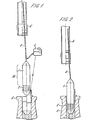
- the present invention provides a guide for use in connecting a pipe 6 to a sub sea wellhead 3, which guide comprises a guide post 1 having a reversibly radially expandable portion 2 to locate in and rigidly attach the guide post to the sub sea wellhead, and an elongate portion 1A to be received in the end of the pipe, characterised in that the elongate portion comprises means 12 rotatable about the axis of the post for supporting the pipe for rotation to connect to the wellhead.
- the guide post will normally be suspended on suitable means for lowering it from the sea surface, e.g. a cable or hollow pipe, usually attached on the axis of the guide post and preferably providing a hydraulic connection to the guide post when the expandable portion is hydraulically actuated.
- suitable means for lowering it from the sea surface e.g. a cable or hollow pipe, usually attached on the axis of the guide post and preferably providing a hydraulic connection to the guide post when the expandable portion is hydraulically actuated.
- the expandable portion may be an expanding mandrel and the expanding mandrel will preferably be wholly or partially segmented and co-operate with-wedging surfaces so that as the segments move over the wedging surfaces, the outside diameter either increases or decreases, depending on the direction of motion.
- the actuating means will preferably be hydraulic, and able to cause expansion or contraction of the mandrel.
- the elongate portion of the guide post preferably comprises a rotatable sleeve which may be supported on the post on low-friction bearings to provide the said means for supporting the pipe for rotation.
- the invention includes a process for connecting a pipe 6 to a sub sea wellhead 3 to which it is connectable which process comprises suspending the pipe 6 above the wellhead 3, lowering through the bore of the pipe a guide comprising guide post 1 and means 4 for lowering the guide post 1, the guide post 1 having a reversibly radially expandable portion 2 and .an elongate portion lA
- Figure 2 is a view showing the guide post of Figure 1. latched into the wellhead prior to lowering the conductor.
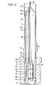
- Figure 3 is a half-sectional view showing the guide post of Figure 1 latched into the wellhead, with the conductor pipe lowered over the post.
- the guide includes a guide post 1 having toward one end an expanding mandrel 2, each end of the post 1 being frusto conical to aid location in the wellhead and pipe as described hereafter.
- the post 1 bears, above the expanding mandrel 2 a sleeve 12 having an exterior surface 12A.
- Sleeve 12 is rotatable on bearings 13.
- the body of the post 1 under the sleeve 12 is recessed so that the outer surface 12A of the sleeve lies flush with or slightly raised above the adjacent parts of the post.
- a bearing 13 is provided at each end of the sleeve and may be a plain bearing or a roller, e.g. a tapered roller, bearing.
- a shaped nut 14 maintains the sleeve 12 in position on the post.
- the post 1 is hollow allowing a pair of hydraulic lines 19 (one shown in ghost lines) connecting a hydraulic line containing cable 4 on which the guide post is suspended to a distribution block 20 which provides connection to two hydraulic lines 8 and 15 serving the expanding mandrel 12.
- Cable 4 is attached by a gland 17 to the top of post 1.
- the internal gland nut 18 acts to grip reinforcing armour wires around the cable 4. Sealing between the block 20 and the bore of post 1 is effected typically by resilient seal 21.
- a pipe as the means for lowering the guide post.
- Such a pipe would normally be composed of many threaded sections assembled onto one another as the guide is lowered.
- Expanding mandrel 2 includes a set of segments 2A movable radially outward and inward in response to the motion of a hydraulic piston 9 located in a cylinder on the axis of the post and bearing pins lO, which each engage a segment 2A and drive their segment 2A up and down over a set of wedge surfaces 11 so that downward motion of the piston 9 upon introduction of fluid into the cylinder above the piston via line 8 expands the mandrel.
- the segments are held against the wedge surfaces by sprung bands 16.
- Line 15 communicates between the distribution block 20 and the cylinder below piston 9. The mandrel is shown in Figur 3 in the expanded position.
- the ratio length of the rotatable portion of the guide post to its diameter is generally preferably about 3:1 but may be less e.g. 2:1.
- the length necessary to enable a sufficient moment to be applied to the pipe to bend it into alignment will depend on the operating circumstances and the material of which the pipe is constructed.
- the tolerance in angular alignment of tie back conductor to wellhead to which conventional drilling equipment operates is about 1.5°.
- the present invention as specifically described enables an angular misalignment of 1.5° to be corrected and may allow greater misalignments, e.g. of up to 2.5°, to be corrected.
- the cable is tensioned by pulling at the platform deck.
- the conductor 6 is lowered the remaining distance to the wellhead, and is guided laterally by the cable to the top of the post which has a conical shape to assist the lower end of the conductor on its way down over the major portion of the post.
- the conductor bore has a close sliding fit over the sleeve 12 which extends over the outside of the major portion of the post. The combination of the weight of the conductor and two spaced points of contacts between the conductor and the sleeve is able to supply a bending moment to the conductor to eliminate most of any initial angular misalignment.
- the pipe and wellhead have co-operating connecting means which are connectable by rotation of the pipe.
- the connecting means are shown as scree threaded portions.
- an alternative possibility is schematically shown, namely a latch mechanism actuated by rotation.
- the post 1 can be released. This is done by pressurising the second hydraulic line 15 which pushes the piston 9 upwards to raise the mandrel segments 2A.
- the wellhead may have an extension piece rigidly attached above it, which piece may have a threaded or other type of profile for effecting a connection to the tie-back conductor.
- the guide post may be adapted to locate into the wellhead extension piece, rather than into the wellhead itself.
- the apparatus is useful in a situation where sub sea wells have been drilled through a seabed template and a platform structure has been positioned over them.
- a conductor usually consisting of 40 ft. long lengths of pipe which are joined in the vertical position and progressively lowered through guide funnels in the structure, is supported 30 to 50 ft. above the mating wellhead.
- the connector between the conductor and wellhead will generally require conductor rotation to permit make- up. It may be a direct threaded type connection; or may require rotation to clamp a lock ring, e.g. the Koomey Triple - S System.
- a lock ring e.g. the Koomey Triple - S System.
- the sleeve over the major portion of the post is mounted on low-friction bearings, so that when torque is applied to the conductor at platform deck level, the two parts of the connector are held in axial alignment and the bending moment is supported by the bearings. This eliminates the possibilities of
- the expanding mandrel can be released and the post can be recovered by pulling it up through the conductor.
- the invention includes a guide for use in connecting a pipe to an open hollow structure by a joint formed upon rotation of the pipe or the structure and comprising a guide post having a radially expandable portion to locate in and rigidly attach the guide post to the hollow structure, and an elongate portion providing means rotatable about the axis of the post and to be received in the end of the pipe to support the pipe for rotation relative to the hollow structure.
Landscapes
- Life Sciences & Earth Sciences (AREA)
- Engineering & Computer Science (AREA)
- Geology (AREA)
- Mining & Mineral Resources (AREA)
- Physics & Mathematics (AREA)
- Environmental & Geological Engineering (AREA)
- Fluid Mechanics (AREA)
- General Life Sciences & Earth Sciences (AREA)
- Geochemistry & Mineralogy (AREA)
- Earth Drilling (AREA)
- Excavating Of Shafts Or Tunnels (AREA)
- Rigid Pipes And Flexible Pipes (AREA)
Applications Claiming Priority (2)
| Application Number | Priority Date | Filing Date | Title |
|---|---|---|---|
| GB7928006 | 1979-08-10 | ||
| GB7928006 | 1979-08-10 |
Publications (3)
| Publication Number | Publication Date |
|---|---|
| EP0024180A2 true EP0024180A2 (de) | 1981-02-25 |
| EP0024180A3 EP0024180A3 (en) | 1981-05-13 |
| EP0024180B1 EP0024180B1 (de) | 1984-03-07 |
Family
ID=10507143
Family Applications (1)
| Application Number | Title | Priority Date | Filing Date |
|---|---|---|---|
| EP80302738A Expired EP0024180B1 (de) | 1979-08-10 | 1980-08-08 | Beim Herstellen von Rohrverbindungen verwendete Führungen und Verfahren zum Herstellen von Rohrverbindungen |
Country Status (5)
| Country | Link |
|---|---|
| US (1) | US4391331A (de) |
| EP (1) | EP0024180B1 (de) |
| CA (1) | CA1146848A (de) |
| GB (1) | GB2056009B (de) |
| NO (1) | NO154704C (de) |
Cited By (1)
| Publication number | Priority date | Publication date | Assignee | Title |
|---|---|---|---|---|
| FR2582047A1 (fr) * | 1985-05-17 | 1986-11-21 | Inst Francais Du Petrole | Dispositif d'assemblage a distance de deux organes |
Families Citing this family (6)
| Publication number | Priority date | Publication date | Assignee | Title |
|---|---|---|---|---|
| GB2069647B (en) | 1980-02-14 | 1983-10-05 | Brown John Constr | Guides for forming underwater connections |
| US4670143A (en) * | 1985-09-03 | 1987-06-02 | Bratten Jack R | Horizontal drum filter having a drive wheel and interfitting tube sections |
| NO159193C (no) * | 1986-07-22 | 1988-12-07 | Elf Aquitaine | Fremgangsmaate og anordning for befestigelse av en avtagbar styrestolpe. |
| US4797029A (en) * | 1986-11-24 | 1989-01-10 | National Oilwell | Remotely installing a tubular string |
| US5246075A (en) * | 1992-01-06 | 1993-09-21 | National-Oilwell | Guide post latching mechanism |
| NO180055C (no) * | 1992-10-16 | 1997-02-05 | Norsk Hydro As | Utblåsningssikring for avstenging av et ringrom mellom en borestreng og en brönnvegg ved boring etter olje eller gass |
Family Cites Families (10)
| Publication number | Priority date | Publication date | Assignee | Title |
|---|---|---|---|---|
| US3142344A (en) * | 1960-12-21 | 1964-07-28 | Shell Oil Co | Method and apparatus for drilling underwater wells |
| US3163228A (en) * | 1961-11-06 | 1964-12-29 | Shell Oil Co | Cable latching device |
| US3301324A (en) * | 1964-06-12 | 1967-01-31 | A 1 Bit & Tool Company | Swivel for supporting drill string in submerged casing head |
| US3380528A (en) * | 1965-09-24 | 1968-04-30 | Tri State Oil Tools Inc | Method and apparatus of removing well pipe from a well bore |
| US3528686A (en) * | 1968-06-24 | 1970-09-15 | Vetco Offshore Ind Inc | Rotatable casing hanger apparatus |
| GB1343897A (de) * | 1971-03-10 | 1974-01-16 | ||
| GB1380971A (en) * | 1972-01-10 | 1975-01-22 | Shell Int Research | Underwater wellhead equipment |
| US3851714A (en) * | 1973-12-26 | 1974-12-03 | Mission Mfg Co | Rotary drilling head and method of breaking pipe joints |
| US3987741A (en) * | 1976-01-12 | 1976-10-26 | The United States Of America As Represented By The Secretary Of The Navy | Remote unmanned work system (ruws) mating latch |
| US4086776A (en) * | 1977-04-11 | 1978-05-02 | Compagnie Francaise Des Petroles | Lock means for a tension line |
-
1980
- 1980-08-08 US US06/176,293 patent/US4391331A/en not_active Expired - Lifetime
- 1980-08-08 GB GB8025921A patent/GB2056009B/en not_active Expired
- 1980-08-08 EP EP80302738A patent/EP0024180B1/de not_active Expired
- 1980-08-08 NO NO802393A patent/NO154704C/no unknown
- 1980-08-08 CA CA000357893A patent/CA1146848A/en not_active Expired
Cited By (2)
| Publication number | Priority date | Publication date | Assignee | Title |
|---|---|---|---|---|
| FR2582047A1 (fr) * | 1985-05-17 | 1986-11-21 | Inst Francais Du Petrole | Dispositif d'assemblage a distance de deux organes |
| EP0203003A1 (de) * | 1985-05-17 | 1986-11-26 | Institut Français du Pétrole | Fernbediente Vorrichtung zum Verbinden von zwei Teilen |
Also Published As
| Publication number | Publication date |
|---|---|
| NO154704C (no) | 1986-12-03 |
| NO802393L (no) | 1981-02-11 |
| EP0024180A3 (en) | 1981-05-13 |
| GB2056009B (en) | 1983-06-08 |
| EP0024180B1 (de) | 1984-03-07 |
| US4391331A (en) | 1983-07-05 |
| GB2056009A (en) | 1981-03-11 |
| CA1146848A (en) | 1983-05-24 |
| NO154704B (no) | 1986-08-25 |
Similar Documents
| Publication | Publication Date | Title |
|---|---|---|
| US4427072A (en) | Method and apparatus for deep underwater well drilling and completion | |
| EP0840834B1 (de) | Vorrichtung und verfahren zum bohren und kompletieren mehrerer bohrungen | |
| US5671812A (en) | Hydraulic pressure assisted casing tensioning system | |
| EP0713953B1 (de) | Verfahren zum Bohren und Komplettieren von Bohrlöchern | |
| US4147221A (en) | Riser set-aside system | |
| CA1067399A (en) | Well flow control system and method | |
| CA1252387A (en) | Method and apparatus for connecting a tubular element to an underwater wellhead | |
| US3722585A (en) | Apparatus for aligning and connecting underwater flowlines | |
| IE44051B1 (en) | Marine riser system and method for intalling the same | |
| US6367554B1 (en) | Riser method and apparatus | |
| US5450904A (en) | Adjustable tieback sub | |
| WO2013167872A2 (en) | Drilling and lining subsea wellbores | |
| US6601656B2 (en) | Method and apparatus for drilling an offshore underwater well | |
| US3252528A (en) | Method of drilling from a fully floating platform | |
| US3486555A (en) | Small diameter riser pipe system | |
| US3459259A (en) | Mudline suspension system | |
| EP0024180B1 (de) | Beim Herstellen von Rohrverbindungen verwendete Führungen und Verfahren zum Herstellen von Rohrverbindungen | |
| US4105068A (en) | Apparatus for producing oil and gas offshore | |
| US4797029A (en) | Remotely installing a tubular string | |
| US12428918B2 (en) | Offshore drilling apparatus and methods | |
| US3341398A (en) | Offshore deep drilling method from a floating platform | |
| US11692407B1 (en) | Systems and methods for a mudline suspension system corrosion cap and running tool with shearing screws | |
| GB1590387A (en) | Apparatus and method for conducting deep water well operations | |
| GB2085990A (en) | Guidance system for vertical pipe connections | |
| NO20170948A1 (en) | System and method for reducing fatigue on a well structure |
Legal Events
| Date | Code | Title | Description |
|---|---|---|---|
| PUAI | Public reference made under article 153(3) epc to a published international application that has entered the european phase |
Free format text: ORIGINAL CODE: 0009012 |
|
| AK | Designated contracting states |
Designated state(s): FR IT NL |
|
| PUAL | Search report despatched |
Free format text: ORIGINAL CODE: 0009013 |
|
| AK | Designated contracting states |
Designated state(s): FR IT NL |
|
| 17P | Request for examination filed |
Effective date: 19810921 |
|
| RAP1 | Party data changed (applicant data changed or rights of an application transferred) |
Owner name: JOHN BROWN ENGINEERS & CONSTRUCTORS LIMITED |
|
| ITF | It: translation for a ep patent filed | ||
| GRAA | (expected) grant |
Free format text: ORIGINAL CODE: 0009210 |
|
| AK | Designated contracting states |
Designated state(s): FR IT NL |
|
| ET | Fr: translation filed | ||
| PGFP | Annual fee paid to national office [announced via postgrant information from national office to epo] |
Ref country code: FR Payment date: 19840730 Year of fee payment: 5 |
|
| PLBE | No opposition filed within time limit |
Free format text: ORIGINAL CODE: 0009261 |
|
| STAA | Information on the status of an ep patent application or granted ep patent |
Free format text: STATUS: NO OPPOSITION FILED WITHIN TIME LIMIT |
|
| 26N | No opposition filed | ||
| PGFP | Annual fee paid to national office [announced via postgrant information from national office to epo] |
Ref country code: NL Payment date: 19860831 Year of fee payment: 7 |
|
| PG25 | Lapsed in a contracting state [announced via postgrant information from national office to epo] |
Ref country code: NL Effective date: 19880301 |
|
| NLV4 | Nl: lapsed or anulled due to non-payment of the annual fee | ||
| PG25 | Lapsed in a contracting state [announced via postgrant information from national office to epo] |
Ref country code: FR Free format text: LAPSE BECAUSE OF NON-PAYMENT OF DUE FEES Effective date: 19880429 |
|
| REG | Reference to a national code |
Ref country code: FR Ref legal event code: ST |