EP0024183A1 - Procédé pour détecter des défauts dans le manchon protecteur électriquement conducteur d'un câble - Google Patents
Procédé pour détecter des défauts dans le manchon protecteur électriquement conducteur d'un câble Download PDFInfo
- Publication number
- EP0024183A1 EP0024183A1 EP80302744A EP80302744A EP0024183A1 EP 0024183 A1 EP0024183 A1 EP 0024183A1 EP 80302744 A EP80302744 A EP 80302744A EP 80302744 A EP80302744 A EP 80302744A EP 0024183 A1 EP0024183 A1 EP 0024183A1
- Authority
- EP
- European Patent Office
- Prior art keywords
- coils
- serving
- cable
- sheath
- monitoring
- Prior art date
- Legal status (The legal status is an assumption and is not a legal conclusion. Google has not performed a legal analysis and makes no representation as to the accuracy of the status listed.)
- Ceased
Links
- 238000000034 method Methods 0.000 title claims description 29
- 238000012544 monitoring process Methods 0.000 claims description 15
- 230000008878 coupling Effects 0.000 claims description 5
- 238000010168 coupling process Methods 0.000 claims description 5
- 238000005859 coupling reaction Methods 0.000 claims description 5
- 238000012806 monitoring device Methods 0.000 claims description 3
- 230000001939 inductive effect Effects 0.000 claims description 2
- 238000002347 injection Methods 0.000 claims 5
- 239000007924 injection Substances 0.000 claims 5
- 230000008859 change Effects 0.000 abstract description 16
- 230000005540 biological transmission Effects 0.000 description 7
- 230000015556 catabolic process Effects 0.000 description 3
- 239000004020 conductor Substances 0.000 description 3
- 238000001514 detection method Methods 0.000 description 3
- 230000006866 deterioration Effects 0.000 description 3
- 230000004048 modification Effects 0.000 description 3
- 238000012986 modification Methods 0.000 description 3
- 239000004411 aluminium Substances 0.000 description 2
- 229910052782 aluminium Inorganic materials 0.000 description 2
- XAGFODPZIPBFFR-UHFFFAOYSA-N aluminium Chemical compound [Al] XAGFODPZIPBFFR-UHFFFAOYSA-N 0.000 description 2
- 230000000694 effects Effects 0.000 description 2
- 239000012530 fluid Substances 0.000 description 2
- 238000009413 insulation Methods 0.000 description 2
- 239000004033 plastic Substances 0.000 description 2
- 229920003023 plastic Polymers 0.000 description 2
- 230000035945 sensitivity Effects 0.000 description 2
- 239000002689 soil Substances 0.000 description 2
- 230000036962 time dependent Effects 0.000 description 2
- 239000011248 coating agent Substances 0.000 description 1
- 238000000576 coating method Methods 0.000 description 1
- 230000007797 corrosion Effects 0.000 description 1
- 238000005260 corrosion Methods 0.000 description 1
- 238000010586 diagram Methods 0.000 description 1
- 230000005684 electric field Effects 0.000 description 1
- 230000005611 electricity Effects 0.000 description 1
- 230000004907 flux Effects 0.000 description 1
- 238000005259 measurement Methods 0.000 description 1
- 229910052751 metal Inorganic materials 0.000 description 1
- 239000002184 metal Substances 0.000 description 1
- 238000011084 recovery Methods 0.000 description 1
- 238000002310 reflectometry Methods 0.000 description 1
- 230000000246 remedial effect Effects 0.000 description 1
- 238000005070 sampling Methods 0.000 description 1
- 239000013598 vector Substances 0.000 description 1
- 238000012795 verification Methods 0.000 description 1
- XLYOFNOQVPJJNP-UHFFFAOYSA-N water Substances O XLYOFNOQVPJJNP-UHFFFAOYSA-N 0.000 description 1
- 229910000859 α-Fe Inorganic materials 0.000 description 1
Images

Classifications
-
- G—PHYSICS
- G01—MEASURING; TESTING
- G01R—MEASURING ELECTRIC VARIABLES; MEASURING MAGNETIC VARIABLES
- G01R31/00—Arrangements for testing electric properties; Arrangements for locating electric faults; Arrangements for electrical testing characterised by what is being tested not provided for elsewhere
- G01R31/08—Locating faults in cables, transmission lines, or networks
- G01R31/081—Locating faults in cables, transmission lines, or networks according to type of conductors
- G01R31/083—Locating faults in cables, transmission lines, or networks according to type of conductors in cables, e.g. underground
-
- G—PHYSICS
- G01—MEASURING; TESTING
- G01V—GEOPHYSICS; GRAVITATIONAL MEASUREMENTS; DETECTING MASSES OR OBJECTS; TAGS
- G01V3/00—Electric or magnetic prospecting or detecting; Measuring magnetic field characteristics of the earth, e.g. declination, deviation
- G01V3/08—Electric or magnetic prospecting or detecting; Measuring magnetic field characteristics of the earth, e.g. declination, deviation operating with magnetic or electric fields produced or modified by objects or geological structures or by detecting devices
- G01V3/10—Electric or magnetic prospecting or detecting; Measuring magnetic field characteristics of the earth, e.g. declination, deviation operating with magnetic or electric fields produced or modified by objects or geological structures or by detecting devices using induction coils
- G01V3/104—Electric or magnetic prospecting or detecting; Measuring magnetic field characteristics of the earth, e.g. declination, deviation operating with magnetic or electric fields produced or modified by objects or geological structures or by detecting devices using induction coils using several coupled or uncoupled coils
Definitions
- the present invention relates to a method of, and apparatus for, locating an electrical current carrying element, for example in a subterranean location, and, particularly where the element is the served (i.e. insulated) sheath of an electric cable, for detecting the presence of a fault or of any deterioration therein.
- Synthetic plastics covered (served) aluminium sheaths can become extensively damaged by corrosion when the sheath comes in contact with water and soil as a result of a failure in the serving.
- the normal ohmic resistance of the sheath to earth is typically of order 4 to 8 M ⁇ When this resistance is 0.5 M ⁇ it means there is an electrically conducting path which is a result of sheath insulation (serving) breakdown at one or more points along the length of the cable. Such breakdown can be caused by pin-holes, cracks or mechanical damage in the plastic serving, often in places where two cables are joined. Ultimately the electric cable will become damaged and it is essential therefore that a fault in the served sheath is detected at an early stage.
- the present invention enables a fault in the serving to be located even before any damage to the sheath has occurred, as well as enabling sheath faults to be located.
- Underground power cables in the United Kingdom include E.H.V. (extra high voltage) all insulated routes which are usually buried to a depth of 1 to 2 metres. Physical considerations preclude the use of techniques such as Pulse Reflectometry for fault finding whilst other existing methods require a power source of high voltage (typically 2 KVA or more). These methods sample the ELECTRIC FIELD generated by the applied potential difference with contact or capacitively coupled electrodes.
- a method of monitoring the performance of an elongate electrically conductive cable sheath and its serving including the steps of injecting a signal of pre-determined frequency into the sheath, and examining the profile in amplitude and/or gradient of the resulting magnetic H field.
- the profile of the magnetic H field can be examined from one side to the other of the sheath (TRANSVERSE mode) in order to locate the sheath or along the sheath (LONGITUDINAL mode) in order to determine the position of a serving fault.
- apparatus for examining the profile in amplitude and/or gradient of a magnetic field comprising two coils arranged in fixed relationship to each other in the same plane and amplitude and phase difference monitoring devices for respectively indicating the amplitude of emfs induced in the coils due to the magnetic field and indicating the difference in phase between the emfs induced in those coils.
- apparatus for examining the profile in amplitude and/or gradient of a MAGNETIC H field comprising three coils disposed in a plane in two pairs with the coils of each pair arranged in a fixed relationship to each other and with the coils being disposed with their centres on the vertices of a right angled triangle.
- four coils could be provided arranged in two pairs with the line joining the centres of the coil of one pair orthogonal to the line joining the centres of coils of the second pair.
- injecting is used to cover both direct and indirect coupling between the cables sheath and the source of the signal.
- the coupling when direct, may be a direct electrical connection and, when indirect, may be inductive or capacitive.
- Figure 1 shows diagrammatically a cross-section of a typical EHV (extra high voltage) underground electricity power cable. /
- Figure 2 shows a side-view of the cable sheath.
- Figure 3 diagrammatically shows the magnetic field surrounding a cable sheath of the type shown in Figure 2 when the earth links are removed and an input signal injected at the left-hand end of the sheath.
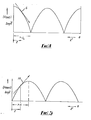
- Figure 4 shows a standing wave generated on a short circuited transmission line which is long compared with the wavelength.
- Figure 5 shows a standing wave generated on an open circuited transmission line which is long compared with the wavelength.
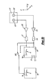
- Figure 6 shows a block diagram of a detector for monitoring the amplitude and sign of an A.C. magnetic field gradient.
- Figure 7 shows a modification of the detector shown in Figure 6.
- Figure 7a shows another modification of the detector shown in Figure 6
- Figure 8 shows a uniform two conductor transmission line with associated parameters which is an approximation of the hollow cable sheath excited at one end at a single frequency.
- the standard underground power transmission cable length L between substations (a) and (b) is typically of the order 3 Km.
- the cable generally comprises three conductors 11, 12 and 13 symmetrically submerged in oil or gas 14 at high pressure contained within a surrounding metal, normally aluminium, sheath 15 with an insulating coating (serving) 16.
- the sheath 15 is connected to earth at both substations by respective links 21 and 22.
- the resistance from the sheath to earth should be of order 4 M ⁇ or greater.
- a value for this resistance of less than 0.5 M ⁇ is defined, or classed, as a fault.
- the fault or faults may be anywhere along the cable length and as the cable can be buried to a depth typically of order 1 to 2 metres, locating the fault simply and accurately is a first preferential step, in the remedy of the fault.
- Rate of change of voltage (v) and current (i) with propagation distance (z) along is given by:-
- an alternating signal is injected into one end of the cable sheath 15.
- the injected signal is a square wave with amplitude ⁇ 15 volts.
- the frequency of the injected signal is chosen so that a quareter wavelength is longer than the typical distance between substations. This is not essential but as will be seen later will avoid ambiguous readings due to normally occuring nodes and anti-nodes in the electromagnetic profile.
- the frequency of the injected signal is approximately 5KHz with corresponding wavelength 60 Km.
- the quarter wavelength is thus 15 Km which is much larger than the typical distance between substations which is of order 1.5 to 3 Km.
- a magnetic H field is generated around the cable and this field appears on the surface directly above the buried cable.
- This field is diagrammatically illustrated in Figure 3 and is utilised to locate the reference points P 1 , P2' P3' P4 etc., which lie in the horizontal earth plane above the cable, as well as the position of a fault or faults along the length of the cable's served sheath.
- the PHASE DIFFERENCE between the induced E.M.F.s in the two coils is a measure of the spatial gradient FG of H , the slope of the tangent near the origin in Figure 5. This slope is smoothly varying and so the phase difference between the induced E.M.F.s in the two coils must be smoothly varying along the length of a fault free cable, provided the coil assembly is coupled at the same position in the toroidal field, say points P 1 , P2' P 3 , P 4 , etc. of Figure 3.
- the points P i (where i is any integer) on the surface are those of maximum sensitivity and are points of equal phase difference between the induced E.M.F.s in the two coils when mounted rigidly as in Figure 6 (coils 62 and 63 on assembly 61) and moved in the ⁇ y direction on the surface across the position of the cable (TRANSVERSE scan).
- the line joining the centre of each coil is also in the ⁇ y direction for this scan mode.
- a fault is not necessarily a short circuit but can be a low resistance path.
- the field gradient therefore varies in shape and a fault is characterised by a change in the magnitude of the induced E.M.F.s accompanied by a sharp change in phase (in the LONGITUDINAL scan).
- the coil support 61 is moved in the z direction along the line through the surface points P .
- the line joining the centre of each coil 62 and 63 is in the - z direction.
- the detector 61 comprises two coils 62, 63 each 3.8 cm in diameter in fixed relationship to each other with their centres 4 cm apart. Each coil has a ferrite core, and is tuned to the fundamental frequency of the transmitter. The axis of each coil is in the x direction (based on our previous notation). The detector is also fitted with a spirit level. This detector will sample the H -field gradient on the surface above the buried cable in both the Transverse and Longitudinal scans.
- Respective matched coils 62, 63 are connected to respective ones of a pair of buffer amplifiers 64, 65, which have a matched voltage gain and then through respective mains frequency filters (rejection) 66, 67 to a phase meter 69.
- the phase meter 69 bears a scale 70 and two lights 71, 72 which respectively indicate, when lit, that the signal from coil 62 leads the signal from coil 63 in phase or vice versa. It is useful to monitor the field strength as well as the magnitude and sign of the field gradient.
- the signal from each coil in turn can be connected to a peak rectifier 73 with signal amplitude scale 74 by means of a switch 68.
- the detector head 61 can be fitted with a handle so that the head 61 can be easily kept horizontal in the surface plane by a moving operator during the fault finding or monitoring procedure.
- the whole apparatus of Figure 6 can be incorporated on the handle to the detector head 61 or alternatively the control electronics and meters etc. can be in a separate unit and electrically connected to the head/handle unit.
- the operator walks along the cable length with the detector head 61 held out in front and moved from side to side over the estimated cable position to sample the H -field gradient in magnitude and direction using the information from the phase meter and amplitude meter.
- the phase meter will indicate a change from coil 62 leads coil 63 to coil 62 lags coil 63, or vice versa, due to the fact that the linkage of the H -field with the coils alters and with it the E.M.F. induced in the coils. It is thus possible to position the detector head at a point where the toroidal field gradient (transverse mode) is sharpest as at the surface points P i in Figure 3.
- the H field-gradient can be examined as before along the length of the cable.
- a node or dip is formed in the overall electromagnetic wave profile at the fault location and the H -field gradient changes sign. This reversal can be detected by the phasemeter with the head orientated for the longitudinal mode (i.e. the line joining the centre of each coil aligned in the - z direction).
- the transmitter may be connected to the other end of the cable and a second scan taken in the opposite direction and cross correlation techniques, using pairs of phase readings and pairs of amplitude readings may be used to define accurately the position of the fault. Such verification may be particularly useful, or even necessary, where the fault is relatively small.
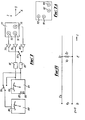
- FIG. 7 A more convenient embodiment is shown in Figure 7 where the detector head 77 comprises three coils 74, 75, 76 disposed in a horizontal plane at the vertices of an isosceles right angled triangle. This axis of each coil is normal to the horizontal plane.
- the coil 74 at the vertex containing theright angle is the reference coil.
- coils 74 and 76 are used in the TRANSVERSE scan to locate the surface reference points P i whilst coils 74 and 75 are used in the LONGITUDINAL scan to examine the field gradient along the cable length.
- the x-coordinate of the 3-dimensional coordinate system is vertically out of the page of the drawing.
- Respective matched coils 74, 75, 76 are connected to respective buffer amplifiers 78, 79, 80 having a matched voltage gain.
- the output from 78 passes through mains frequency rejection filter 81.
- the output from either 79 or 80 passes through mains frequency rejection filter 82 via switch 83.
- the signals from either coil pair 74, 75 or 74, 76 pass to the phase meter 85 which has scale 86 and lead/lag lights 87, 88 as before.
- the signal from each coil in turn can be connected to peak rectifier 89 with scale 90 by means of switches 83 and 84.
- a four coil detector head could also be used in two orthogonal pairs. Four such coils 90 to 93 are shown diagrammatically in Figure 7a.
- the H-field gradient is sampled near the substation at which the signal is injected and the direction of the detector noted with respect to the cable. Sampling is repeatedly carried out along the length of the cable until the detector indicates a change in sign of the phase angle. The fault lies at that point. Or, in the case of a high resistance fault at the point where a change in amplitude is accompanied by an abrupt change in phase angle.
- the method and apparatus of the invention may also be used to determine the depth of good cables and to monitor deterioration of cables and to locate large obstacles underground as their existence modifies the magnetic field.
- the method of the invention can also be used on:
- the standing wave profile on the line quickly regains its normal form after the fault it is not normally necessary to correct the fault before proceeding to locate the next fault along the line.
- the standing wave pattern recovery is usually achieved within 20 to 100 metres of a fault.
- the E.M.F. amplitude generated in the detection will give an indication of the type of fault located.
- a modification to the above described method can be used for locating faults and monitoring the performance, for example, of domestic 3-phase power supply systems, either linked or unlinked, where the frequency of the injected signal is chosen so that the wavelength is short compared with the length of the transmission line in question.
- a series of nodes and antinodes will be formed in the magnetic H field profile along the line, through which the field gradient will change sign.
- a fault along the line will modify the H field profile and will enable the position of the fault to be determined.
- Transmission line theory is utilised to locate gradients in the MAGNETIC H field component of an electromagnetic wave, in two dimensions.
- a high voltage source is not required and thus the risk of a dielectric breakdown at points where the insulation (serving) is partly damaged, is avoided.
- Some alternative methods involve increasing the severity of the fault by the passage of high currents in order to 'burn' a lower resistance path into the serving thus increasing the sensitivity of the method. However, this can create faults where previously none existed.
- the power requirements are of the order of - 15 volts at 250 mA.
- the apparatus can be used in electromagnetically noisy environments and is not affected by moving vehicles or large moving metallic objects.
- Each fault has a characteristic field profile, and the field profile of a good cable is distinct from a faulty one.
Landscapes
- Physics & Mathematics (AREA)
- General Physics & Mathematics (AREA)
- Engineering & Computer Science (AREA)
- Remote Sensing (AREA)
- Life Sciences & Earth Sciences (AREA)
- Electromagnetism (AREA)
- Environmental & Geological Engineering (AREA)
- Geology (AREA)
- General Life Sciences & Earth Sciences (AREA)
- Geophysics (AREA)
- Locating Faults (AREA)
Applications Claiming Priority (4)
| Application Number | Priority Date | Filing Date | Title |
|---|---|---|---|
| GB7928837 | 1979-08-18 | ||
| GB7928837 | 1979-08-18 | ||
| GB7929258 | 1979-08-22 | ||
| GB7929258 | 1979-08-22 |
Publications (1)
| Publication Number | Publication Date |
|---|---|
| EP0024183A1 true EP0024183A1 (fr) | 1981-02-25 |
Family
ID=26272619
Family Applications (1)
| Application Number | Title | Priority Date | Filing Date |
|---|---|---|---|
| EP80302744A Ceased EP0024183A1 (fr) | 1979-08-18 | 1980-08-11 | Procédé pour détecter des défauts dans le manchon protecteur électriquement conducteur d'un câble |
Country Status (2)
| Country | Link |
|---|---|
| US (1) | US4438389A (fr) |
| EP (1) | EP0024183A1 (fr) |
Cited By (6)
| Publication number | Priority date | Publication date | Assignee | Title |
|---|---|---|---|---|
| WO1994006027A1 (fr) * | 1992-09-09 | 1994-03-17 | Henkels & Mccoy, Inc. | Systeme et procede d'utilisation pour l'etude de la corrosion du neutre |
| US5691644A (en) * | 1996-05-10 | 1997-11-25 | Henkels & Mccoy | Neutral corrosion condition survey-mitigating induced voltage effects |
| GB2331157A (en) * | 1985-08-23 | 1999-05-12 | Licentia Gmbh | An arrangement for determining the geometry and gradients of magnetic fields |
| CN104698339A (zh) * | 2015-02-11 | 2015-06-10 | 国家电网公司 | 一种手持式墙壁内电源线路故障查找仪 |
| CN111742356A (zh) * | 2018-03-27 | 2020-10-02 | 株式会社京三制作所 | 检测系统 |
| CN118983719A (zh) * | 2024-10-22 | 2024-11-19 | 江苏志方电力工程有限公司 | 一种电力工程电缆铺设的检修设备 |
Families Citing this family (34)
| Publication number | Priority date | Publication date | Assignee | Title |
|---|---|---|---|---|
| DE3518004C2 (de) * | 1985-05-18 | 1994-03-24 | Hdw Elektronik Gmbh | Meßanordnung zur Ortsbestimmung von Fehlern in Kabeln |
| FI863487A7 (fi) * | 1986-08-27 | 1988-02-28 | Matti Viikari | Sähkömagneettiseen induktioon perustuva menetelmä ja laite johtavassa väliaineessa olevien johteiden sähköisen eristeen kunnon tarkkailuun. |
| US5126654A (en) * | 1989-02-10 | 1992-06-30 | New York Gas Group | Non-invasive, high resolution detection of electrical currents and electrochemical impedances at spaced localities along a pipeline |
| US5093622A (en) * | 1989-03-17 | 1992-03-03 | Minnesota Mining And Manufacturing Company | Method and apparatus for determining direction to and position of an underground conductor |
| US5084710A (en) * | 1989-07-28 | 1992-01-28 | Minnesota Mining And Manufacturing Company | Electronic means for switching antennas to a common bus |
| US5087873A (en) * | 1990-04-02 | 1992-02-11 | New York Gas Group | Non-invasive, high resolution detection of electrical currents and electrochemical impedances at spaced localities along a pipeline |
| US5231355A (en) * | 1990-06-18 | 1993-07-27 | The Charles Machine Works, Inc. | Locator transmitter having an automatically tuned antenna |
| US5065098A (en) * | 1990-06-18 | 1991-11-12 | The Charles Machine Works, Inc. | System for locating concealed underground objects using digital filtering |
| US5194816A (en) * | 1990-10-19 | 1993-03-16 | Westinghouse Electric Corp. | Method and apparatus for locating electrical shorts between concealed conductive objects |
| US5365163A (en) * | 1992-09-29 | 1994-11-15 | Minnesota Mining And Manufacturing Company | Sensor array for circuit tracer |
| GB9223094D0 (en) * | 1992-11-04 | 1992-12-16 | Beeman Terrence M | A fault-locator for use in locating high-resistance ground-faults in or on concentric ground electric power cables |
| US5471143A (en) * | 1993-01-29 | 1995-11-28 | Minnesota Mining And Manufacturing Co. | Apparatus for locating buried conductors using phase-shifted signals |
| US5430379A (en) * | 1993-08-27 | 1995-07-04 | Minnesota Mining And Manufacturing Company | Conductor locator adapter for electronic markers |
| JP3386928B2 (ja) * | 1995-06-05 | 2003-03-17 | 重男 森本 | ロケータ機能付地中埋設物表示シート |
| CA2158916A1 (fr) * | 1995-09-22 | 1995-11-17 | Don A. Lulham | Methode et appareil de detection de defaillance dans les conducteurs enfouis |
| GB9617605D0 (en) * | 1996-08-22 | 1996-10-02 | Radiodetection Ltd | Detecting the condition of a conceald object |
| DE19708518C2 (de) * | 1997-03-03 | 1999-05-27 | Signal Concept Gmbh | Verfahren und Vorrichtung zum Auffinden einer Defektstelle in einer Leiterschleife |
| US5977773A (en) * | 1997-08-15 | 1999-11-02 | The United States Of America As Represented By The Administrator Of The National Aeronautics And Space Administration | Non-intrusive impedance-based cable tester |
| US5894223A (en) * | 1997-09-24 | 1999-04-13 | The United States Of America As Represented By The Administrator Of The National Aeronautics And Space Administration | Non-intrusive cable tester |
| US6121779A (en) * | 1998-08-14 | 2000-09-19 | General Electric Company | Bulk current injection system |
| SE515105C2 (sv) * | 1998-12-18 | 2001-06-11 | Abb Ab | Förfarande och anordning för lokalisering av en kabel i en likströmsförbindelse |
| DE19913954A1 (de) * | 1999-03-26 | 2000-09-28 | Nokia Mobile Phones Ltd | Verfahren zur Ermittlung der Position einer in einem Antennenpfad vorhandenen Fehlstelle sowie Kommunikationsvorrichtung zur Durchführung des Verfahrens |
| US6541976B1 (en) * | 1999-12-17 | 2003-04-01 | Geometrics Group, Inc. | Under and above ground, radio frequency driven element, metal locating system |
| GB0013620D0 (en) | 2000-06-06 | 2000-07-26 | Howell Mark I | A technique for finding the position and depth of any buried pipeline or cable accurately, even where it may be lying close to other long buried conductors |
| US6529006B1 (en) | 2001-10-31 | 2003-03-04 | Paul Hayes | Method and apparatus for resolving the position and identity of buried conductive bodies |
| DE10162802B4 (de) * | 2001-12-19 | 2005-12-22 | Tutech Innovation Gmbh | Verfahren und Vorrichtung zur Ermittlung von Inhomogenitäten des Schirmverhaltens geschirmter elektrischer Leiter |
| RU2285269C1 (ru) * | 2005-06-07 | 2006-10-10 | Сергей Сергеевич Сергеев | Способ определения места повреждения на трассе подземной электропроводящей линии |
| US7622931B2 (en) * | 2005-10-03 | 2009-11-24 | University Of Utah Research Foundation | Non-contact reflectometry system and method |
| US7755360B1 (en) | 2005-10-24 | 2010-07-13 | Seektech, Inc. | Portable locator system with jamming reduction |
| US8000936B2 (en) * | 2008-11-10 | 2011-08-16 | Saudi Arabian Oil Company | Data analysis system for determining coating conditions of a buried pipeline |
| US7876110B2 (en) * | 2008-11-10 | 2011-01-25 | Saudi Arabian Oil Company | Method and apparatus for simulating electrical characteristics of a coated segment of a pipeline |
| US7880484B2 (en) * | 2008-11-10 | 2011-02-01 | Saudi Arabian Oil Company | Method and apparatus for estimating the condition of a coating on an underground pipeline |
| SE542098C2 (en) * | 2017-12-21 | 2020-02-25 | Husqvarna Ab | System method and a detecting device related to robotic working tools for detecting a break in a robotic work tool system boundary wire |
| CN111896842A (zh) * | 2020-07-27 | 2020-11-06 | 国网上海市电力公司 | 基于区间斜率的配电网弧光高阻故障区段定位方法 |
Citations (8)
| Publication number | Priority date | Publication date | Assignee | Title |
|---|---|---|---|---|
| FR1523055A (fr) * | 1967-05-18 | 1968-04-26 | Siemens Ag | Dispositif de mesure et de protection pour des lignes à haute tension |
| AT288545B (de) * | 1968-04-13 | 1971-03-10 | Dynatronic Gmbh & Co Kg | Verfahren zum Orten eines Fehlers einer elektrischen Leitung |
| US3623142A (en) * | 1969-10-08 | 1971-11-23 | Mayes O Key | Cable conductor locator including cam-operated switch means for impressing a pulsing current on the conductor |
| DE2640012A1 (de) * | 1976-09-04 | 1978-03-16 | Ruhrkohle Ag | Verfahren und geraet zur ortung von kurzschluessen in mit mehreren adern und einer oder mehreren abschirmungen versehenen leitungen, insbesondere des berg- und tunnelbaus |
| DE2651814A1 (de) * | 1976-11-12 | 1978-05-18 | Henneberg Apparatebau Hans | Verfahren und schaltungsanordnung zur induktiven ortung einer fehlerstelle in einem erdkabel |
| DE2735756A1 (de) * | 1977-08-09 | 1979-02-22 | Licentia Gmbh | Verfahren und vorrichtung zur erdschlussrichtungsbestimmung in kompensierten netzen |
| DE1791027B2 (de) * | 1968-08-30 | 1979-04-26 | Seba-Dynatronic Industrie-Elektronic Gmbh & Co Kg, 8601 Baunach | Verfahren zum Orten eines Fehlers einer elektrischen Leitung |
| AT357634B (de) * | 1976-12-14 | 1980-07-25 | Oesterr Studien Atomenergie | Vorrichtung zur identifizierung von elektrischen leitern |
Family Cites Families (12)
| Publication number | Priority date | Publication date | Assignee | Title |
|---|---|---|---|---|
| US1297929A (en) | 1915-09-28 | 1919-03-18 | Gen Electric | Differentially-connected exploring-coils. |
| US2427666A (en) | 1943-04-20 | 1947-09-23 | Bell Telephone Labor Inc | Magnetic field strength indicator |
| GB577080A (en) | 1944-02-09 | 1946-05-03 | Victor Planer | Method and device for the location of faults, depth determination and tracing of electrical conductors |
| US3568048A (en) | 1968-12-09 | 1971-03-02 | Mcphar Geophysics Ltd | Three coil system for geophysical prospecting utilizing magnetic time transients |
| US3745452A (en) | 1971-02-23 | 1973-07-10 | J Osburn | Magnetic field gradient apparatus and method for detecting pipe line corrosion |
| US3792350A (en) | 1972-03-15 | 1974-02-12 | Bell Telephone Labor Inc | Detection of metalshield faults in buried cable |
| FR2289919A1 (fr) | 1974-10-31 | 1976-05-28 | Coprelec | Dispositif pour la detection de ruptures de fuites dans des conducteurs electriques enterres ou noyes dans un materiau solide, et applications de ce dispositif |
| FR2307279A1 (fr) | 1975-04-07 | 1976-11-05 | Procedes Electro Magnetiques | Procede et dispositif pour l'etude du sous-sol et de sa nature electro-magnetique |
| GB1509914A (en) | 1975-05-23 | 1978-05-04 | Electrolocation Ltd | Detector systems for electromagnetic surveying |
| US4134061A (en) | 1977-02-02 | 1979-01-09 | Gudgel Howard S | Pipe current detector with plural magnetic flux detectors |
| FR2389139A1 (fr) | 1977-04-28 | 1978-11-24 | Socotec Sa | Procedes et dispositifs de detection electromagnetique des defauts de cables chauffants |
| US4220913A (en) | 1978-05-23 | 1980-09-02 | Electrolocation Limited | Apparatus for and methods of electromagnetic surveying of elongated underground conductors |
-
1980
- 1980-08-11 EP EP80302744A patent/EP0024183A1/fr not_active Ceased
- 1980-08-15 US US06/179,278 patent/US4438389A/en not_active Expired - Lifetime
Patent Citations (8)
| Publication number | Priority date | Publication date | Assignee | Title |
|---|---|---|---|---|
| FR1523055A (fr) * | 1967-05-18 | 1968-04-26 | Siemens Ag | Dispositif de mesure et de protection pour des lignes à haute tension |
| AT288545B (de) * | 1968-04-13 | 1971-03-10 | Dynatronic Gmbh & Co Kg | Verfahren zum Orten eines Fehlers einer elektrischen Leitung |
| DE1791027B2 (de) * | 1968-08-30 | 1979-04-26 | Seba-Dynatronic Industrie-Elektronic Gmbh & Co Kg, 8601 Baunach | Verfahren zum Orten eines Fehlers einer elektrischen Leitung |
| US3623142A (en) * | 1969-10-08 | 1971-11-23 | Mayes O Key | Cable conductor locator including cam-operated switch means for impressing a pulsing current on the conductor |
| DE2640012A1 (de) * | 1976-09-04 | 1978-03-16 | Ruhrkohle Ag | Verfahren und geraet zur ortung von kurzschluessen in mit mehreren adern und einer oder mehreren abschirmungen versehenen leitungen, insbesondere des berg- und tunnelbaus |
| DE2651814A1 (de) * | 1976-11-12 | 1978-05-18 | Henneberg Apparatebau Hans | Verfahren und schaltungsanordnung zur induktiven ortung einer fehlerstelle in einem erdkabel |
| AT357634B (de) * | 1976-12-14 | 1980-07-25 | Oesterr Studien Atomenergie | Vorrichtung zur identifizierung von elektrischen leitern |
| DE2735756A1 (de) * | 1977-08-09 | 1979-02-22 | Licentia Gmbh | Verfahren und vorrichtung zur erdschlussrichtungsbestimmung in kompensierten netzen |
Cited By (10)
| Publication number | Priority date | Publication date | Assignee | Title |
|---|---|---|---|---|
| GB2331157A (en) * | 1985-08-23 | 1999-05-12 | Licentia Gmbh | An arrangement for determining the geometry and gradients of magnetic fields |
| GB2331157B (en) * | 1985-08-23 | 1999-09-22 | Licentia Gmbh | An arragement for determining the geometry and radients of magnetic fields |
| WO1994006027A1 (fr) * | 1992-09-09 | 1994-03-17 | Henkels & Mccoy, Inc. | Systeme et procede d'utilisation pour l'etude de la corrosion du neutre |
| US5498967A (en) * | 1992-09-09 | 1996-03-12 | Henkels & Mccoy, Inc. | System and methods of use for conducting a neutral corrosion survey |
| US5654642A (en) * | 1992-09-09 | 1997-08-05 | Henkels & Mccoy | System and method of use for conducting a neutral corrosion survey |
| US5691644A (en) * | 1996-05-10 | 1997-11-25 | Henkels & Mccoy | Neutral corrosion condition survey-mitigating induced voltage effects |
| CN104698339A (zh) * | 2015-02-11 | 2015-06-10 | 国家电网公司 | 一种手持式墙壁内电源线路故障查找仪 |
| CN111742356A (zh) * | 2018-03-27 | 2020-10-02 | 株式会社京三制作所 | 检测系统 |
| CN111742356B (zh) * | 2018-03-27 | 2022-09-20 | 株式会社京三制作所 | 检测系统 |
| CN118983719A (zh) * | 2024-10-22 | 2024-11-19 | 江苏志方电力工程有限公司 | 一种电力工程电缆铺设的检修设备 |
Also Published As
| Publication number | Publication date |
|---|---|
| US4438389A (en) | 1984-03-20 |
Similar Documents
| Publication | Publication Date | Title |
|---|---|---|
| US4438389A (en) | Method for utilizing three-dimensional radiated magnetic field gradients for detecting serving faults in buried cables | |
| US5352984A (en) | Fault and splice finding system and method | |
| US4048558A (en) | Method and apparatus for detecting metal failures in situ | |
| US4325022A (en) | Cable shield fault location using a capacitive-inductive coupler | |
| CN102298104B (zh) | 一种桥架电缆接地故障检测方法 | |
| US5726574A (en) | Method of locating a fault in an electric power cable | |
| US4471294A (en) | Electrical conduit defect location | |
| US3990003A (en) | Pulsed loop antenna-conduit electromagnetic radiator test technique for electromagnetic shielding flaw detection in buried conduits and shielded conductors | |
| Nissen et al. | Theoretical background for the TDR methodology | |
| GB2057147A (en) | Detecting Faults in Buried Cables | |
| US4241305A (en) | Method and apparatus for locating faults in electric cables | |
| EP3767314B1 (fr) | Localisation de pannes dans un système hvdc | |
| US4839598A (en) | Method for testing underground electric cables | |
| US4866391A (en) | System and method of simultaneously measuring a multiplicity of grounds on utility poles | |
| CN103424628A (zh) | 测量平行电网线路正序阻抗的方法 | |
| EP0843823B1 (fr) | Detection et localisation de fuites de courant | |
| WO1988001748A1 (fr) | Procede et dispositif servant a determiner l'etat de l'isolation d'un objet compose d'un materiau electroconducteur, revetu par une isolation electrique et place dans un milieu electroconducteur | |
| Shafiq et al. | Online partial discharge diagnostics in medium voltage branched cable networks | |
| Das et al. | Investigations on feasibility of fault detection in underground power cables using SFRA | |
| Jackson et al. | Partial discharges in power-cable joints: their propagation along a crossbonded circuit and methods for their detection | |
| Van der Wielen et al. | Synchronization of on-line PD detection and localization setups using pulse injection | |
| Paophan et al. | Study of a partial discharge location technique for power cables using high frequency current transducer | |
| Morin et al. | In-service location of partial discharge sites in polymeric distribution cables using capacitive and inductive probes | |
| Predus et al. | The importance of the metal reinforcement of low voltage cables in the process of identifying defects | |
| Rynjah et al. | Microcontroller-based Cable Fault and Insulation Flaw Detection in Low-Voltage Cables |
Legal Events
| Date | Code | Title | Description |
|---|---|---|---|
| PUAI | Public reference made under article 153(3) epc to a published international application that has entered the european phase |
Free format text: ORIGINAL CODE: 0009012 |
|
| AK | Designated contracting states |
Designated state(s): AT BE CH DE FR GB IT LU NL SE |
|
| 17P | Request for examination filed |
Effective date: 19810813 |
|
| STAA | Information on the status of an ep patent application or granted ep patent |
Free format text: STATUS: THE APPLICATION HAS BEEN REFUSED |
|
| 18R | Application refused |
Effective date: 19841116 |
|
| RIN1 | Information on inventor provided before grant (corrected) |
Inventor name: DE SA, ALTEN JOSE AUGUSTO |