EP0024269A2 - Système de récupération de chaleur - Google Patents
Système de récupération de chaleur Download PDFInfo
- Publication number
- EP0024269A2 EP0024269A2 EP80850122A EP80850122A EP0024269A2 EP 0024269 A2 EP0024269 A2 EP 0024269A2 EP 80850122 A EP80850122 A EP 80850122A EP 80850122 A EP80850122 A EP 80850122A EP 0024269 A2 EP0024269 A2 EP 0024269A2
- Authority
- EP
- European Patent Office
- Prior art keywords
- air
- heat
- inlet
- channels
- exhaust air
- Prior art date
- Legal status (The legal status is an assumption and is not a legal conclusion. Google has not performed a legal analysis and makes no representation as to the accuracy of the status listed.)
- Withdrawn
Links
- 238000005192 partition Methods 0.000 claims abstract description 12
- 239000003570 air Substances 0.000 description 66
- 239000007789 gas Substances 0.000 description 11
- 230000001172 regenerating effect Effects 0.000 description 7
- 230000008021 deposition Effects 0.000 description 4
- 238000010438 heat treatment Methods 0.000 description 4
- 238000004140 cleaning Methods 0.000 description 3
- 238000009413 insulation Methods 0.000 description 3
- 229910052704 radon Inorganic materials 0.000 description 3
- SYUHGPGVQRZVTB-UHFFFAOYSA-N radon atom Chemical compound [Rn] SYUHGPGVQRZVTB-UHFFFAOYSA-N 0.000 description 3
- 238000009423 ventilation Methods 0.000 description 3
- 241000894006 Bacteria Species 0.000 description 2
- 241000700605 Viruses Species 0.000 description 2
- 238000004891 communication Methods 0.000 description 2
- 239000003925 fat Substances 0.000 description 2
- 230000008014 freezing Effects 0.000 description 2
- 238000007710 freezing Methods 0.000 description 2
- 231100000614 poison Toxicity 0.000 description 2
- 230000007096 poisonous effect Effects 0.000 description 2
- 230000035943 smell Effects 0.000 description 2
- 238000007592 spray painting technique Methods 0.000 description 2
- 239000012080 ambient air Substances 0.000 description 1
- 238000007664 blowing Methods 0.000 description 1
- 238000010276 construction Methods 0.000 description 1
- 238000011109 contamination Methods 0.000 description 1
- 238000010411 cooking Methods 0.000 description 1
- 230000001627 detrimental effect Effects 0.000 description 1
- 238000005265 energy consumption Methods 0.000 description 1
- 238000011010 flushing procedure Methods 0.000 description 1
- 238000012423 maintenance Methods 0.000 description 1
- 230000005855 radiation Effects 0.000 description 1
- 238000007789 sealing Methods 0.000 description 1
- 230000000087 stabilizing effect Effects 0.000 description 1
- 239000000126 substance Substances 0.000 description 1
- 230000001360 synchronised effect Effects 0.000 description 1
- XLYOFNOQVPJJNP-UHFFFAOYSA-N water Substances O XLYOFNOQVPJJNP-UHFFFAOYSA-N 0.000 description 1
Images



Classifications
-
- F—MECHANICAL ENGINEERING; LIGHTING; HEATING; WEAPONS; BLASTING
- F28—HEAT EXCHANGE IN GENERAL
- F28D—HEAT-EXCHANGE APPARATUS, NOT PROVIDED FOR IN ANOTHER SUBCLASS, IN WHICH THE HEAT-EXCHANGE MEDIA DO NOT COME INTO DIRECT CONTACT
- F28D17/00—Regenerative heat-exchange apparatus in which a stationary intermediate heat-transfer medium or body is contacted successively by each heat-exchange medium, e.g. using granular particles
Definitions
- the present invention relates to a heat recovering system of the kind which comprises at least one comparatively elongated pack of heat absorbing plates between which there are formed flow channels for the inlet and exhaust air and wherein the air flow direction through the heat absorbing pack is periodically reversed.
- Another type of regenerative recovering systems operates with a flushing cycle whereby the return air amount may be kept practically close to zero.
- the surfaces which are sequentially swept by inlet and exhaust air are gradually contaminated by deposits, such as fats, drips from spray painting, oil residues and other types of contamination that may be present in the exhaust air.
- bacteria and virus may be transferred from the exhaust air to the inlet air, and there also exists a risk for enrichment of bacteria, virus and beyond all spores from such organisms at the heat absorbing surfaces.
- One object of the present invention has been to provide a heat recovering system which combines the advantages and eliminates the drawbacks of the recuperative and regenerative recovering systems.
- the inlet air channels and the exhaust air channels are hermetically sealed off from each other.
- the exhaust air and the inlet air are caused to flow in different channels and the heat is transferred from one side of the partition between the channels, is stored in the partition and is finally emitted from the other side of the partition.
- the partitions between the flows which are air or gastight sealed from each other, are used as heat absorbing elements in one or more heat accumulators at the same time as similar partitions of one or more other heat accumulators are used as heat emitting elements.
- the function of the heat absorbing and heat emitting accumulators is shifted after are suitable period of time. Of course, the actual length of that period is chosen in such a manner that optimum efficiency and and economy are obtained.
- an aggregate according to the present invention may be placed at any location within a building.
- the volume and length of the inlet and exhaust ducts have no influence on the function.
- the ducts as well as the aggregate are preferably installed in heated readily accessible spaces whereby the duct losses are reduced down to a minimum.
- the kithen air from homes may be taken care of in the aggregate, provided it is reasonably filtered from fats that would otherwise contaminate the ducts and the aggregate and reduce the efficiency. Air from toilets and other sanitary spaces may similarly be taken care of without risk for transfer of evil smell.
- the aggregate may advantageously be used in hospitals and operation rooms in as much as the inlet and exhaust flows pass hermetically sealed off from each other. Further, the aggregate may be used for instance in connection with spray painting provided that one also here works with a reasonable cleaning of the gas to prevent clogging. The aggregate is also useful in the chemical industry where one often works with exhaustion of air which is contaminated by poisonous gases. Still further, the aggregate eliminates all risks for return of radon gas with returned air.
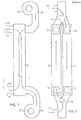
- the aggregate as shown in FIGS. 1 and 2 comprises an exhaus fan 10 and an inlet fan 11 and two heat accumulators 12 and 13.
- Each one of these accumulators comprises a pack of plates which: are disposed in such a manner that flow channels are formed between adjacent plates, and sealing strips are interposed betwe the plates in such a manner that individual flow channels for inlet air and exhaust air are formed which channels are hermetically sealed off from each other.
- the exhaust air is sucked in through the opening and is blown by the fan 10 through the accumulator 13 and out in the ambient air through the opening 15
- the exhaust air flows through.the accumulator 13 as long as the flap valve 16 is in its left hand position as shown in FIG. 2. After a suitable period of time, e.g. one minute, the valve 16 is shifted to its right hand position (shown in dashed lines in FIG. 2), and the exhaust air is then passed through the accumulator 12.
- Inlet air from outside is sucked in through the opening 17 by means of the fan 11 and is blown through the accumulator 12 (in the cycle where the exhaust air is blown through the accumulator 13).
- the valve flap 18 is shifted from its right hand position in FIG. 2 to its left hand position (shown in dashed lines in FIG. 2) synchronously with the shifting of the valve flap 16 from its left hand position into its right hand position as mentioned above.
- the inlet air flows through the accumulator 13 whereas the exhaust air flows through the accumulator 12.
- the exhaust air leaves through, the opening 15 when flowing through the accumulator 13 and through the opening 19 when flowing throuc the accumulator 12.
- the inlet air flows into an inlet duct (not shown) through an opening 20 as it has passed the accumulator 13 and through an opening 21 as the inlet air has passed the accumulator 12.
- the openings 15 and 19 lead to one and the same exhaust air duct (not shown in FIG. 1) and the openings 20 and 21 (similarly one hidden behind the other in FIG. 1) lead to one and the same inlet air duct (not shown).
- the second embodiment as shown in FIGS. 3 and 4 has an inle air fan 22 which sucks the inlet air through the accumulators 12 and 13, respectively, rather than blowing the inlet air throu the accumulators as was the case with the embodiment of FIGS. 1 and 2.
- the valves (not shown) have been synchronized in that they are disposed on one and the same shaft 2
- the moisture conditions are always important with all heat exchangers. According to the present invention there is achievE a direct transport out of the humidity of the room air.
- the inlet air will contain only the humidity which is contained in the outer cool air. This may be a drawback, such as in homes, where the humidity may become too low in wintertime.
- in stables and green houses for instance, where it i; desirable to have as big a transport out of the moisture as eve: possible the properties of the aggregate according to the invention are very valuable.
- the exhaust air heats the cooled accumulator it will pass the dew point with an attendant deposition of condensate which flows downwardly. Therefore, the accumulator should be designed in such manner that a proper outflow of the condensate is achieved.
- the preheating is utilized in the system and does not involve a loss.
- the preheating may be controlled by means of a thermostate from a suitable point and is preferably carried out by means of a heating battery in the inlet air duct.
- the third embodiment of the heat recovering system according to the invention may be said to constitute a regenerative heat recovering system with eliminated valve leaking, rectifying of the air flows and cleanblowing.
- This system comprises two heat accumulators 30, 31, each one comprising elongated packs of heat absorbing and emitting plates disposed close to each other so that air flow channels are formed between them.
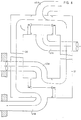
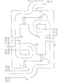
- the ends of the accumulators 30, 31 are inter- conneted by means of distribution boxes 32 and 33, respectively, FIGS. 5 - 8.
- Each box has a central, longitudinal partition (not shown) which forms two chambers, such as chambers 34,34 in FIG. 5.
- the ends of these chambers are connected to the accumulators 30, 31 through valves 36,37 and 38,39, respectively, and centrally the chambers 32,33 are connected to inlet and exhaust ducts such as the ducts 40A and 41A in direct communication with the ventilated space and inlet duct 40B and exhaust duct 41B-in direct communication with the atmosphere outside the ventilated space, as shown diagrammatically in FIGS. 5-8.
- valves 36-39 are of the type that closes one of the valve flaps of each set prior to the opening of the corresponding other flap of the set in question to avoid any leakage of e.g. contaminated air from one chamber into the other as the air flow directions are changed as will be set forth below.
- the left hand accumulator 30 absorbs heat from the exhaust air, coming from duct 41A and leaving through duct 41B whereas the inlet air from duct 40B is heated in accumulator 31 and enters the ventilated space through duct 40A.
- the left hand accumulator 30 is cleaned by means of a small portion of the inlet air flow from chamber 32, which cleaning may take a few seconds only and has no significant detrimental effect to the overall efficiency.
- the right hand accumulator 31 absorbs heat from the exhaust air of duct 41A whereas the left hand accumulator 30 emits heat to the inlet air which enters through duct 40B. passes the accumulator 30 and enters the ventilated space through the duct 40A.
- stage four as depicted in FIG. 8, the right hand accumulator 31 is cleaned by means of inlet air which is being branched off from the flow that would otherwise enter the ventilated space through the duct 40A.
- valves could be designed to operate individually in the desired'order but normally the valves are arranged in pair at opposite ends of one and the same shaft, as shown dia- gramatically in FIGS. 5-8 whereby the general assembly becomes less complicated.
Landscapes
- Engineering & Computer Science (AREA)
- Physics & Mathematics (AREA)
- Thermal Sciences (AREA)
- Mechanical Engineering (AREA)
- General Engineering & Computer Science (AREA)
- Waste-Gas Treatment And Other Accessory Devices For Furnaces (AREA)
- Ventilation (AREA)
Priority Applications (1)
| Application Number | Priority Date | Filing Date | Title |
|---|---|---|---|
| EP80850122A EP0024269A3 (fr) | 1980-08-13 | 1980-08-13 | Système de récupération de chaleur |
Applications Claiming Priority (1)
| Application Number | Priority Date | Filing Date | Title |
|---|---|---|---|
| EP80850122A EP0024269A3 (fr) | 1980-08-13 | 1980-08-13 | Système de récupération de chaleur |
Publications (2)
| Publication Number | Publication Date |
|---|---|
| EP0024269A2 true EP0024269A2 (fr) | 1981-02-25 |
| EP0024269A3 EP0024269A3 (fr) | 1981-04-22 |
Family
ID=8187483
Family Applications (1)
| Application Number | Title | Priority Date | Filing Date |
|---|---|---|---|
| EP80850122A Withdrawn EP0024269A3 (fr) | 1980-08-13 | 1980-08-13 | Système de récupération de chaleur |
Country Status (1)
| Country | Link |
|---|---|
| EP (1) | EP0024269A3 (fr) |
Cited By (7)
| Publication number | Priority date | Publication date | Assignee | Title |
|---|---|---|---|---|
| EP0078783A1 (fr) * | 1981-11-03 | 1983-05-11 | Verdal Maskinverkstad A/S | Appareil pour la récupération de chaleur d'un espace et pour la ventilation |
| EP0091890A1 (fr) * | 1982-03-26 | 1983-10-19 | Scan Development Oy | Dispositif de récupération de chaleur et de ventilation d'un espace |
| EP0095510A4 (fr) * | 1981-12-07 | 1984-04-13 | Matsushita Electric Industrial Co Ltd | Systeme d'echange thermique. |
| WO1984002392A1 (fr) * | 1982-12-15 | 1984-06-21 | Svante Thunberg | Installation de ventilation |
| WO2015139885A3 (fr) * | 2014-03-18 | 2015-11-26 | Siegenia-Aubi Kg | Dispositif de ventilation |
| ITUB20152468A1 (it) * | 2015-07-24 | 2017-01-24 | Thesan S P A | Scambiatore di calore con movimentazione dei flussi. |
| EP3754263A1 (fr) | 2019-04-09 | 2020-12-23 | Tempeff Inc. | Appareil d'échange d'énergie pour chaleur sensible et latente |
Family Cites Families (8)
| Publication number | Priority date | Publication date | Assignee | Title |
|---|---|---|---|---|
| FR613822A (fr) * | 1925-04-02 | 1926-11-30 | Perfectionnements apportés aux échangeurs de température entre fluides, notamment à ceux pour gaz de combustion et air | |
| DE894977C (de) * | 1943-06-05 | 1953-10-29 | Ind G M B H | Foerderrohrleitung fuer brennbares, staubfoermiges Gut |
| FR1045913A (fr) * | 1951-11-14 | 1953-12-02 | Installation pour la ventilation de locaux avec récupération de la chaleur de l'air vicié pour préchauffer l'air frais | |
| CH313864A (de) * | 1952-06-19 | 1956-05-15 | Parsons & Co Ltd C A | Verfahren zum Reinhalten und Reinigen von Wärmeaustauschern und Vorrichtung zur Durchführung des Verfahrens |
| AT242721B (de) * | 1961-05-05 | 1965-10-11 | Jean Prat | Einrichtung zur Abfuhr und Umsetzung der in Zeitabständen anfallenden Abgaswärme von Konvertern oder Lichtbogenöfen sowie Betriebsverfahren für dieselbe |
| FR1350871A (fr) * | 1962-12-21 | 1964-01-31 | Perfectionnements aux récupérateurs de chaleur | |
| DE2201559A1 (de) * | 1972-01-13 | 1973-07-19 | Motoren Werke Mannheim Ag | Plattenwaermetauscher, insbesondere luftvorwaermer |
| US4049404A (en) * | 1975-07-31 | 1977-09-20 | Combustion Research Corporation | Ventilation system with thermal energy recovery |
-
1980
- 1980-08-13 EP EP80850122A patent/EP0024269A3/fr not_active Withdrawn
Cited By (8)
| Publication number | Priority date | Publication date | Assignee | Title |
|---|---|---|---|---|
| EP0078783A1 (fr) * | 1981-11-03 | 1983-05-11 | Verdal Maskinverkstad A/S | Appareil pour la récupération de chaleur d'un espace et pour la ventilation |
| EP0095510A4 (fr) * | 1981-12-07 | 1984-04-13 | Matsushita Electric Industrial Co Ltd | Systeme d'echange thermique. |
| EP0091890A1 (fr) * | 1982-03-26 | 1983-10-19 | Scan Development Oy | Dispositif de récupération de chaleur et de ventilation d'un espace |
| WO1984002392A1 (fr) * | 1982-12-15 | 1984-06-21 | Svante Thunberg | Installation de ventilation |
| WO2015139885A3 (fr) * | 2014-03-18 | 2015-11-26 | Siegenia-Aubi Kg | Dispositif de ventilation |
| RU2666456C2 (ru) * | 2014-03-18 | 2018-09-07 | Сиегениа-ауби КГ | Вентиляционное устройство и способ его эксплуатации |
| ITUB20152468A1 (it) * | 2015-07-24 | 2017-01-24 | Thesan S P A | Scambiatore di calore con movimentazione dei flussi. |
| EP3754263A1 (fr) | 2019-04-09 | 2020-12-23 | Tempeff Inc. | Appareil d'échange d'énergie pour chaleur sensible et latente |
Also Published As
| Publication number | Publication date |
|---|---|
| EP0024269A3 (fr) | 1981-04-22 |
Similar Documents
| Publication | Publication Date | Title |
|---|---|---|
| CN113124482B (zh) | 一种厨房空气调节系统 | |
| US5632334A (en) | Heat recovery ventilator with room air defrosting feature | |
| CA2059195C (fr) | Systeme de ventilation degivrable | |
| US4149590A (en) | Roof device for air conditioning | |
| US4562955A (en) | Air-conditioner | |
| FI81193C (fi) | Ventilationsapparat med vaermeaotervinning. | |
| CN110594941B (zh) | 一种具有温湿协同调控功能的新风净化装置 | |
| KR970062554A (ko) | 공기흐름전환식 냉난방겸용 공기조화기 | |
| US20120312035A1 (en) | Air conditioning system | |
| CN107990428A (zh) | 家用壁挂式空调器 | |
| US4742957A (en) | Heat recovery ventilator | |
| EP0024269A2 (fr) | Système de récupération de chaleur | |
| US4834285A (en) | Heating and ventilating system | |
| US6450244B1 (en) | Air-to-air heat recovery system | |
| RU2244882C1 (ru) | Энергосберегающая система вентиляции и кондиционирования воздуха | |
| GB2296968A (en) | Heat exchange ventilator | |
| CN105157145A (zh) | 洁净手术室用热管型节能空调机组 | |
| JP2002267215A (ja) | 天井埋込型加湿装置 | |
| JPH04244537A (ja) | 空気調和システム | |
| CN211400140U (zh) | 窗式多功能空气调节中心 | |
| JP2701665B2 (ja) | 空調換気装置 | |
| KR20180107494A (ko) | 통합 세대 환기장치 | |
| JP2001330289A (ja) | 多目的換気システム及び多目的換気システム用送風ユニット | |
| US5460222A (en) | Air renewal device | |
| KR20080109960A (ko) | 트윈형 다단식 2중 전열교환기 |
Legal Events
| Date | Code | Title | Description |
|---|---|---|---|
| PUAI | Public reference made under article 153(3) epc to a published international application that has entered the european phase |
Free format text: ORIGINAL CODE: 0009012 |
|
| PUAL | Search report despatched |
Free format text: ORIGINAL CODE: 0009013 |
|
| AK | Designated contracting states |
Designated state(s): BE CH DE GB IT LU NL SE |
|
| AK | Designated contracting states |
Designated state(s): BE CH DE GB IT LU NL SE |
|
| STAA | Information on the status of an ep patent application or granted ep patent |
Free format text: STATUS: THE APPLICATION IS DEEMED TO BE WITHDRAWN |
|
| 18D | Application deemed to be withdrawn |
Effective date: 19820326 |
|
| RIN1 | Information on inventor provided before grant (corrected) |
Inventor name: MAGNUSSON, BENGT Inventor name: STENFORS, ERIK |