EP0024577A1 - Tambour oscillant pour le traitement continu de pièces au jet abrasif - Google Patents
Tambour oscillant pour le traitement continu de pièces au jet abrasif Download PDFInfo
- Publication number
- EP0024577A1 EP0024577A1 EP80104559A EP80104559A EP0024577A1 EP 0024577 A1 EP0024577 A1 EP 0024577A1 EP 80104559 A EP80104559 A EP 80104559A EP 80104559 A EP80104559 A EP 80104559A EP 0024577 A1 EP0024577 A1 EP 0024577A1
- Authority
- EP
- European Patent Office
- Prior art keywords
- jacket
- drum
- workpieces
- longitudinal direction
- turning
- Prior art date
- Legal status (The legal status is an assumption and is not a legal conclusion. Google has not performed a legal analysis and makes no representation as to the accuracy of the status listed.)
- Granted
Links
- 238000004140 cleaning Methods 0.000 title 1
- 238000005422 blasting Methods 0.000 claims description 12
- 230000007704 transition Effects 0.000 claims 1
- 230000005855 radiation Effects 0.000 abstract 1
- 238000012216 screening Methods 0.000 description 2
- 238000011161 development Methods 0.000 description 1
- 230000018109 developmental process Effects 0.000 description 1
- 238000000034 method Methods 0.000 description 1
- 230000002787 reinforcement Effects 0.000 description 1
Images

Classifications
-
- B—PERFORMING OPERATIONS; TRANSPORTING
- B24—GRINDING; POLISHING
- B24C—ABRASIVE OR RELATED BLASTING WITH PARTICULATE MATERIAL
- B24C3/00—Abrasive blasting machines or devices; Plants
- B24C3/18—Abrasive blasting machines or devices; Plants essentially provided with means for moving workpieces into different working positions
- B24C3/26—Abrasive blasting machines or devices; Plants essentially provided with means for moving workpieces into different working positions the work being supported by barrel cages, i.e. tumblers; Gimbal mountings therefor
- B24C3/266—Abrasive blasting machines or devices; Plants essentially provided with means for moving workpieces into different working positions the work being supported by barrel cages, i.e. tumblers; Gimbal mountings therefor for continuously travelling workpieces
Definitions
- the invention relates to a flow swivel drum, which is provided with an upper jacket opening, is inclined in the longitudinal direction and is pivotally mounted about its axis, for the continuous blasting of workpieces traveling through the drum in the longitudinal direction with the aid of centrifugal wheels.
- Such a flow swivel drum as is known for example from DE-OS 24 24 086, is continuously swiveled between two limit positions during the blasting process.
- the workpieces traveling through the flow swivel drum should not only slide longitudinally along the drum, but also rotate about themselves, so that they are struck on their entire surface by the blasting agent which is blown by the centrifugal wheels through the jacket opening in the drum is blasted. Practice shows that this turning around itself does not take place to the desired extent on all workpieces.
- the invention seeks to remedy this.
- the invention as characterized in the claims, solves the problem of equipping the flow swivel drum with a device which inevitably causes the workpieces in the drum to rotate about themselves brought about, at least significantly favored.
- the workpieces sliding on the inside of the drum shell during its pivoting movement in the circumferential direction can only do this until they reach one of the turning stages.
- the workpiece In the turning stage, the workpiece is initially held longer than it corresponds to the swivel angle of the drum shell; until the workpiece is rolled over when the swivel angle is increased further, which then lies against the inside of the swivel drum with another surface.
- the part of the workpiece surface that faces the opening in the jacket and thus the blast wheels and is blasted changes at the turning stages at the latest every second swivel of the flow swivel drum.
- the flow swivel drum shown in the figures has an inlet drum 1 in the longitudinal direction, followed by a jet drum 2 and then a sieve drum 3.
- the flow swivel drum is - which is not shown in the drawing - inclined in the longitudinal direction, so that Workpieces during the swiveling of the flow swivel drum are conveyed in a natural way from the inlet of the inlet drum 1 to the outlet of the sieve drum 3.
- the inlet drum 1 is narrowed towards the feed side in the manner of a funnel 4.
- the inlet drum 1 has a flange ring 5 on the end face facing the blasting drum 2.
- the sieve drum 3 also has a flange ring 6 on the end face facing the blasting drum 2; followed by a support ring 7 towards the outlet side.
- the bottom of the screening drum 3 is largely designed like a screen 8.
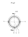
- a race 11 is provided on the outside of its jacket 10 on each end face of the blasting drum 2.
- the race 11 on one end face is screwed to the flange ring 5 of the inlet drum 1, which on the other end face is screwed to the flange ring 6 of the screening drum 3 and the associated support ring 7 by means of screw bolts 12.
- the bottom of the blasting drum 2 is provided with longitudinal openings 13.
- a casing opening 14 is left open in the jacket 10, through which blasting media emerging from centrifugal wheels hit the workpieces transported, pivoted and turned in the blasting drum 2.
- the jacket opening 14 is reinforced laterally in the region of its two side edges by an I-beam 15 each. Other reinforcements are possible.
- the jacket 10 is provided on its side opposite the jacket opening 14 with a turning stage 16.
- the turning stage 16 extends between the inner surfaces of the races 11. It can extend over the entire length of the blasting drum 2.
- a turning bar can also be used as a turning stage or a turning edge can be provided.
- the decisive factor is that when the jet drum 2 is pivoted to the turning stage, bar or edge, the workpieces do not simply slide further along the inner surface of the jacket 10 when the swivel angle is increased, but rather roll over, so that another part of their surface faces the jacket opening 14 , which ensures uniform irradiation of the workpieces.
- the turning stage 16 is in the exemplary embodiment than in the shell 1 0 pushed outwardly formed in a substantially V-shaped groove.
- One leg surface 17 of the turning stage 16 merges tangentially into the jacket 10; the other leg surface 18, which is substantially perpendicular to the first leg surface 17, merges into the jacket with a kink.
Landscapes
- Engineering & Computer Science (AREA)
- Mechanical Engineering (AREA)
- Finish Polishing, Edge Sharpening, And Grinding By Specific Grinding Devices (AREA)
- Preliminary Treatment Of Fibers (AREA)
Priority Applications (1)
| Application Number | Priority Date | Filing Date | Title |
|---|---|---|---|
| AT80104559T ATE2879T1 (de) | 1979-08-16 | 1980-08-01 | Fliess-schwenktrommel fuer das kontinuierliche strahlen von werkstuecken. |
Applications Claiming Priority (2)
| Application Number | Priority Date | Filing Date | Title |
|---|---|---|---|
| DE7923277U | 1979-08-16 | ||
| DE19797923277U DE7923277U1 (de) | 1979-08-16 | 1979-08-16 | Fliess-schwenktrommel fuer das kontinuierliche strahlen von werkstuecken |
Publications (3)
| Publication Number | Publication Date |
|---|---|
| EP0024577A1 true EP0024577A1 (fr) | 1981-03-11 |
| EP0024577B1 EP0024577B1 (fr) | 1983-03-30 |
| EP0024577B2 EP0024577B2 (fr) | 1989-01-11 |
Family
ID=6706597
Family Applications (1)
| Application Number | Title | Priority Date | Filing Date |
|---|---|---|---|
| EP80104559A Expired EP0024577B2 (fr) | 1979-08-16 | 1980-08-01 | Tambour oscillant pour le traitement continu de pièces au jet abrasif |
Country Status (3)
| Country | Link |
|---|---|
| EP (1) | EP0024577B2 (fr) |
| AT (1) | ATE2879T1 (fr) |
| DE (1) | DE7923277U1 (fr) |
Cited By (1)
| Publication number | Priority date | Publication date | Assignee | Title |
|---|---|---|---|---|
| WO1993003888A1 (fr) * | 1991-08-13 | 1993-03-04 | Georg Fischer Giessereianlagen Ag | Machine de grenaillage a turbine |
Families Citing this family (1)
| Publication number | Priority date | Publication date | Assignee | Title |
|---|---|---|---|---|
| DE7923277U1 (de) * | 1979-08-16 | 1979-11-29 | Maschinen- U. Werkzeugfabrik Kabel Vogel & Schemmann Ag, 5800 Hagen | Fliess-schwenktrommel fuer das kontinuierliche strahlen von werkstuecken |
Citations (6)
| Publication number | Priority date | Publication date | Assignee | Title |
|---|---|---|---|---|
| DD34667A (fr) * | ||||
| US2116160A (en) * | 1935-10-22 | 1938-05-03 | Pangborn Corp | Abrading apparatus |
| US2440819A (en) * | 1944-03-09 | 1948-05-04 | Pangborn Corp | Tumbling mill |
| DD109334A5 (fr) * | 1972-09-29 | 1974-11-05 | ||
| DE2424086A1 (de) * | 1974-05-17 | 1975-11-27 | Vogel & Schemmann Masch | Fliesstrommel zur kontinuierlichen bestrahlung von gusstuecken mit hilfe von schleuderraedern |
| DE7923277U1 (de) * | 1979-08-16 | 1979-11-29 | Maschinen- U. Werkzeugfabrik Kabel Vogel & Schemmann Ag, 5800 Hagen | Fliess-schwenktrommel fuer das kontinuierliche strahlen von werkstuecken |
-
1979
- 1979-08-16 DE DE19797923277U patent/DE7923277U1/de not_active Expired
-
1980
- 1980-08-01 AT AT80104559T patent/ATE2879T1/de active
- 1980-08-01 EP EP80104559A patent/EP0024577B2/fr not_active Expired
Patent Citations (6)
| Publication number | Priority date | Publication date | Assignee | Title |
|---|---|---|---|---|
| DD34667A (fr) * | ||||
| US2116160A (en) * | 1935-10-22 | 1938-05-03 | Pangborn Corp | Abrading apparatus |
| US2440819A (en) * | 1944-03-09 | 1948-05-04 | Pangborn Corp | Tumbling mill |
| DD109334A5 (fr) * | 1972-09-29 | 1974-11-05 | ||
| DE2424086A1 (de) * | 1974-05-17 | 1975-11-27 | Vogel & Schemmann Masch | Fliesstrommel zur kontinuierlichen bestrahlung von gusstuecken mit hilfe von schleuderraedern |
| DE7923277U1 (de) * | 1979-08-16 | 1979-11-29 | Maschinen- U. Werkzeugfabrik Kabel Vogel & Schemmann Ag, 5800 Hagen | Fliess-schwenktrommel fuer das kontinuierliche strahlen von werkstuecken |
Cited By (1)
| Publication number | Priority date | Publication date | Assignee | Title |
|---|---|---|---|---|
| WO1993003888A1 (fr) * | 1991-08-13 | 1993-03-04 | Georg Fischer Giessereianlagen Ag | Machine de grenaillage a turbine |
Also Published As
| Publication number | Publication date |
|---|---|
| ATE2879T1 (de) | 1983-04-15 |
| EP0024577B2 (fr) | 1989-01-11 |
| DE7923277U1 (de) | 1979-11-29 |
| EP0024577B1 (fr) | 1983-03-30 |
Similar Documents
| Publication | Publication Date | Title |
|---|---|---|
| DE2303994A1 (de) | Zentrifuge zum trennen von feststofffluessigkeitsgemischen | |
| DE3308586C2 (de) | Vorrichtung zur spitzenlosen, spanenden Außenfeinbearbeitung von länglichen Werkstücken | |
| DE3527923C2 (fr) | ||
| DE3126257A1 (de) | Rundschleifmaschine | |
| DE69834953T2 (de) | Vorschubwalze | |
| DE3216443C1 (de) | Siebvorrichtung zum Abscheiden von Reinigungskoerpern aus dem Kuehlwasserstrom hinter einem Roehrenwaermetauscher | |
| EP0024577B1 (fr) | Tambour oscillant pour le traitement continu de pièces au jet abrasif | |
| EP0383746A1 (fr) | Procédé et installation pour le traitement continu d'une rive d'un produit métallique laminé plat | |
| DE2424086A1 (de) | Fliesstrommel zur kontinuierlichen bestrahlung von gusstuecken mit hilfe von schleuderraedern | |
| EP0371328A2 (fr) | Procédé et dispositif pour le meulage des faces supérieures et/ou des surfaces de guidage des rails ou des choses pareilles | |
| DE3224765C2 (de) | Vorrichtung zum Einbringen von Schüttgut | |
| EP1348806B1 (fr) | Dispositif d'étanchéité | |
| EP0103667B1 (fr) | Dispositif de guidage à quatre rouleaux pour laminoirs | |
| EP0490189B1 (fr) | Installation pour le sablage de la surface de tôles, profilés ou similaire | |
| DE4010436C2 (fr) | ||
| EP1316487A2 (fr) | Installation de dépoussièrage pour carosserie de véhicule | |
| DE2445453C2 (de) | Bohrerschleifeinrichtung | |
| DE2848437C3 (de) | Verstellbare Bandübergabe | |
| DE3128113C2 (de) | Verstellbare Bandübergabe zur Verwendung im untertägigen Grubenbetrieb, mit einer um 360 Grad um einen Mittelpunkt stufenlos drehbaren Schurre | |
| EP0553738A1 (fr) | Dispositif de criblage, en particulier pour trier des déchets | |
| DE3410074C1 (de) | Verstellbare Bandübergabe zur Verwendung im untertägigen Grubenbetrieb | |
| EP0099939B1 (fr) | Machine de traitement au jet abrasif impliquant l'emploi d'un tonneau rotatif pour le traitement de pièces de travail grandes de dimensions égales ou différentes | |
| EP0776840B1 (fr) | Dispositif de retournement | |
| EP0110228A2 (fr) | Cabine de grenaillage et son mode d'utilisation | |
| WO1989000144A1 (fr) | Element tubulaire pour agencement tubulaire de transport |
Legal Events
| Date | Code | Title | Description |
|---|---|---|---|
| PUAI | Public reference made under article 153(3) epc to a published international application that has entered the european phase |
Free format text: ORIGINAL CODE: 0009012 |
|
| AK | Designated contracting states |
Designated state(s): AT BE CH FR GB IT LU NL SE |
|
| 17P | Request for examination filed |
Effective date: 19810605 |
|
| ITF | It: translation for a ep patent filed | ||
| GRAA | (expected) grant |
Free format text: ORIGINAL CODE: 0009210 |
|
| AK | Designated contracting states |
Designated state(s): AT BE CH FR GB IT LI LU NL SE |
|
| REF | Corresponds to: |
Ref document number: 2879 Country of ref document: AT Date of ref document: 19830415 Kind code of ref document: T |
|
| ET | Fr: translation filed | ||
| PGFP | Annual fee paid to national office [announced via postgrant information from national office to epo] |
Ref country code: LU Payment date: 19830720 Year of fee payment: 4 |
|
| PG25 | Lapsed in a contracting state [announced via postgrant information from national office to epo] |
Ref country code: LU Free format text: LAPSE BECAUSE OF NON-PAYMENT OF DUE FEES Effective date: 19830831 |
|
| PLBI | Opposition filed |
Free format text: ORIGINAL CODE: 0009260 |
|
| 26 | Opposition filed |
Opponent name: BMD BADISCHE MASCHINENFABRIK DURLACH GMBH Effective date: 19831117 |
|
| PGFP | Annual fee paid to national office [announced via postgrant information from national office to epo] |
Ref country code: FR Payment date: 19840723 Year of fee payment: 5 |
|
| PGFP | Annual fee paid to national office [announced via postgrant information from national office to epo] |
Ref country code: CH Payment date: 19840829 Year of fee payment: 5 |
|
| PGFP | Annual fee paid to national office [announced via postgrant information from national office to epo] |
Ref country code: SE Payment date: 19840930 Year of fee payment: 5 Ref country code: BE Payment date: 19840930 Year of fee payment: 5 |
|
| PGFP | Annual fee paid to national office [announced via postgrant information from national office to epo] |
Ref country code: AT Payment date: 19860828 Year of fee payment: 7 |
|
| PGFP | Annual fee paid to national office [announced via postgrant information from national office to epo] |
Ref country code: NL Payment date: 19860831 Year of fee payment: 7 |
|
| PG25 | Lapsed in a contracting state [announced via postgrant information from national office to epo] |
Ref country code: AT Effective date: 19870801 |
|
| PG25 | Lapsed in a contracting state [announced via postgrant information from national office to epo] |
Ref country code: SE Effective date: 19870802 |
|
| PG25 | Lapsed in a contracting state [announced via postgrant information from national office to epo] |
Ref country code: LI Effective date: 19870831 Ref country code: CH Effective date: 19870831 |
|
| BERE | Be: lapsed |
Owner name: MASCHINEN- UND WERKZEUGFABRIK KABEL VOGEL & SCHE Effective date: 19870831 |
|
| PG25 | Lapsed in a contracting state [announced via postgrant information from national office to epo] |
Ref country code: NL Effective date: 19880301 |
|
| GBPC | Gb: european patent ceased through non-payment of renewal fee | ||
| NLV4 | Nl: lapsed or anulled due to non-payment of the annual fee | ||
| PG25 | Lapsed in a contracting state [announced via postgrant information from national office to epo] |
Ref country code: FR Free format text: LAPSE BECAUSE OF NON-PAYMENT OF DUE FEES Effective date: 19880429 |
|
| REG | Reference to a national code |
Ref country code: CH Ref legal event code: PL |
|
| REG | Reference to a national code |
Ref country code: FR Ref legal event code: ST |
|
| PG25 | Lapsed in a contracting state [announced via postgrant information from national office to epo] |
Ref country code: GB Free format text: LAPSE BECAUSE OF NON-PAYMENT OF DUE FEES Effective date: 19881118 |
|
| PUAH | Patent maintained in amended form |
Free format text: ORIGINAL CODE: 0009272 |
|
| STAA | Information on the status of an ep patent application or granted ep patent |
Free format text: STATUS: PATENT MAINTAINED AS AMENDED |
|
| 27A | Patent maintained in amended form |
Effective date: 19890111 |
|
| AK | Designated contracting states |
Kind code of ref document: B2 Designated state(s): AT BE CH FR GB IT LU NL SE |
|
| EN3 | Fr: translation not filed ** decision concerning opposition | ||
| PG25 | Lapsed in a contracting state [announced via postgrant information from national office to epo] |
Ref country code: BE Effective date: 19890831 |
|
| EUG | Se: european patent has lapsed |
Ref document number: 80104559.2 Effective date: 19880707 |
|
| APAH | Appeal reference modified |
Free format text: ORIGINAL CODE: EPIDOSCREFNO |