EP0024741A2 - Dispositif de forage pour un robinet de branchement - Google Patents
Dispositif de forage pour un robinet de branchement Download PDFInfo
- Publication number
- EP0024741A2 EP0024741A2 EP80105204A EP80105204A EP0024741A2 EP 0024741 A2 EP0024741 A2 EP 0024741A2 EP 80105204 A EP80105204 A EP 80105204A EP 80105204 A EP80105204 A EP 80105204A EP 0024741 A2 EP0024741 A2 EP 0024741A2
- Authority
- EP
- European Patent Office
- Prior art keywords
- milling
- tube
- valve
- toothed
- milling tube
- Prior art date
- Legal status (The legal status is an assumption and is not a legal conclusion. Google has not performed a legal analysis and makes no representation as to the accuracy of the status listed.)
- Granted
Links
- 238000003801 milling Methods 0.000 claims abstract description 58
- 238000005520 cutting process Methods 0.000 claims abstract description 15
- 238000007789 sealing Methods 0.000 claims abstract description 10
- 238000005553 drilling Methods 0.000 claims abstract description 9
- 238000010079 rubber tapping Methods 0.000 claims description 20
- 238000000034 method Methods 0.000 claims description 7
- 238000010438 heat treatment Methods 0.000 description 3
- 238000005452 bending Methods 0.000 description 2
- 238000003825 pressing Methods 0.000 description 2
- 229910001369 Brass Inorganic materials 0.000 description 1
- 101100293261 Mus musculus Naa15 gene Proteins 0.000 description 1
- 238000013459 approach Methods 0.000 description 1
- 239000010951 brass Substances 0.000 description 1
- 238000005266 casting Methods 0.000 description 1
- 238000013461 design Methods 0.000 description 1
- 238000003754 machining Methods 0.000 description 1
- 239000000463 material Substances 0.000 description 1
- 238000005259 measurement Methods 0.000 description 1
- 239000002184 metal Substances 0.000 description 1
- 239000002245 particle Substances 0.000 description 1
- 238000012549 training Methods 0.000 description 1
- 238000003466 welding Methods 0.000 description 1
Images

Classifications
-
- B—PERFORMING OPERATIONS; TRANSPORTING
- B23—MACHINE TOOLS; METAL-WORKING NOT OTHERWISE PROVIDED FOR
- B23B—TURNING; BORING
- B23B51/00—Tools for drilling machines
- B23B51/04—Drills for trepanning
- B23B51/044—Drills for trepanning with core holding devices
-
- B—PERFORMING OPERATIONS; TRANSPORTING
- B23—MACHINE TOOLS; METAL-WORKING NOT OTHERWISE PROVIDED FOR
- B23B—TURNING; BORING
- B23B2260/00—Details of constructional elements
- B23B2260/138—Screw threads
Definitions
- the invention relates to a valve tapping fitting, in particular for plastic pipelines, in which the lower part of the valve spindle has a valve sealing body which, when the spindle is actuated, works against a valve seat arranged between the tapping and the outlet connection, the valve spindle following the valve sealing body, a metal hollow milling cutter for the boring process carries, whose cylindrical milling tube has several toothed bars with frontal cutting edges, which are evenly distributed on the circumference and slightly inclined in the direction of rotation, and a flute is provided between the toothed bars, and the cup-like milling tube interior serves as a receiving chamber for the drilling chips and the cut-out tubular disk, which is held by an internal thread of the milling tube toothed strips.
- the chips accumulate in these narrow chip drain grooves when the pipe disc has already been largely cut out and the narrow drain channels of the chip grooves have become relatively long. These plastic chips can then be pressed firmly into each other and thereby block the further chip discharge. Due to the high frictional heat that occurs in connection with the heating of the plastic during machining and when cutting the tube disk into the internal thread of the milling tube, these chips can even weld together. As a result of this pressing or welding of the chips, such high forces occur during the further drilling process that individual or even all toothed strips of the milling tube, which is generally made of brass, are bent or even tear.
- the object of the invention is to design the milling tube of the valve tapping fitting in such a way that no deformations or damage to the toothed racks can occur and that the chips are properly removed into the interior of the milling chamber and a low drive torque is ensured.
- the jacket sections provided on the outside of the flutes only insignificantly reduce the clear height of the flutes, since they extend with the same thin walls over the circumference of the flanges, and the fact that the flutes are wider than the toothed strips seen in the circumferential direction, despite the jacket sections still have a sufficiently large free cross-section in the flutes for a perfect removal of the chips.
- the wide flutes form together with those as glides Wall-acting outer jacket sections are good guide channels for the plastic chips, which, because the flutes extend almost to the bottom of the cup-like milling tube interior, remain open in the longitudinal direction of the groove and cause a largely straight-line chip drainage without congestion.
- the flow chips also migrate behind a thick-walled tube disk that already engages deep into the milling tube and rise freely within the izu-uouerscnnittes before they flow to the interior of the milling tube.
- a further reduction in the friction and the drive torque can be achieved in that, according to the feature of claim 2, only a few toothed strips distributed over the circumference of the milling tube are provided with an internal thread and the remaining intermediate toothed strips have no internal thread and are undercut up to the cutting edge.
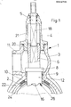
- the tapping fitting 1 designed as a valve tapping bridge is placed on the plastic pipe 2 to be drilled in the usual way.
- the housing 3 of the tapping fitting 1 is closed at the top by a screwed-in housing head 4, in which the upper part 5 of the two-part valve spindle is rotatably mounted.
- the lower part 6 of the valve spindle has a valve sealing body 7 with a sealing ring 8, which can be screwed down until it contacts the seat bushing 9 of the housing 3 and thereby seals the tapping opening 10 against the outlet connection 11 of the housing 3.
- the lower part 6 of the valve spindle carries a hollow milling cutter 12 for the tapping process, which consists of the cylindrical milling tube 13 formed during pressing or casting, with the toothed strips 14 slightly inclined in the direction of rotation relative to the longitudinal axis of the milling cutter, and the flutes 15 therebetween consists.
- the end faces of the toothed strips form the cutting edges 16 of the hollow milling cutter and the cup-like interior 17 of the milling tube 13 serves as a receiving chamber for the plastic chips.
- the square-shaped lower end 18 of the upper valve stem part 5 engages in the inner square 19 of the lower valve stem part 6, whereby the rotary movement is transmitted from the upper part 5 to the lower part 6 of the valve spindle.
- the thread approach 2o of the lower valve spindle part 6 in the internal thread 21 of the housing head 4 moves up or down, as a result of which both the cutting out of the tubular disk from the wall of the plastic pipe 2 and the tight contact of the sealing body 7, 8 against the valve seat o after lowering the Valve stem is effected.
- the housing 3 carries a saddle piece 22 at the bottom, which lies around the upper half of the plastic tube 2 and is screwed like a clamp to a holding piece which surrounds the lower half of the plastic tube.
- the flutes 15 of the milling tube 13 are closed to the outside by consistently thin-walled jacket sections 23 which form a closed cylindrical outer jacket 24 on the milling tube 13 with the thick-walled toothed bars 14.
- the toll sections 23 are undercut.
- the flutes 15 extend almost to the bottom 25 of the milling tube interior 17 and, viewed in the circumferential direction, are wider than the toothed strips 14.
- the toothed strips 14 of the milling tube 13 are provided with an internal thread 26, but only from a few of the cutting edges There are 16 outgoing threads. To the interior of the milling tube 17, these threads 26 of the toothed strips 14 are undercut by a recess 27.
Landscapes
- Engineering & Computer Science (AREA)
- Mechanical Engineering (AREA)
- Lift Valve (AREA)
- Drilling Tools (AREA)
- Fluid-Driven Valves (AREA)
- Multiple-Way Valves (AREA)
Priority Applications (1)
| Application Number | Priority Date | Filing Date | Title |
|---|---|---|---|
| AT80105204T ATE5463T1 (de) | 1979-09-03 | 1980-09-02 | Ventilanbohrarmatur. |
Applications Claiming Priority (2)
| Application Number | Priority Date | Filing Date | Title |
|---|---|---|---|
| DE19792935565 DE2935565A1 (de) | 1979-09-03 | 1979-09-03 | Ventilanbohrarmatur. |
| DE2935565 | 1979-09-03 |
Publications (3)
| Publication Number | Publication Date |
|---|---|
| EP0024741A2 true EP0024741A2 (fr) | 1981-03-11 |
| EP0024741A3 EP0024741A3 (en) | 1981-07-22 |
| EP0024741B1 EP0024741B1 (fr) | 1983-11-30 |
Family
ID=6079944
Family Applications (1)
| Application Number | Title | Priority Date | Filing Date |
|---|---|---|---|
| EP80105204A Expired EP0024741B1 (fr) | 1979-09-03 | 1980-09-02 | Dispositif de forage pour un robinet de branchement |
Country Status (3)
| Country | Link |
|---|---|
| EP (1) | EP0024741B1 (fr) |
| AT (1) | ATE5463T1 (fr) |
| DE (1) | DE2935565A1 (fr) |
Cited By (5)
| Publication number | Priority date | Publication date | Assignee | Title |
|---|---|---|---|---|
| FR2679805A1 (fr) * | 1991-07-29 | 1993-02-05 | Seperef | Foret permettant de menager des decoupes dans la paroi de tuyaux en matiere synthetique. |
| EP0845630A3 (fr) * | 1996-11-30 | 2003-12-17 | Friatec Aktiengesellschaft | Appareil de perçage |
| US7785047B2 (en) * | 2004-11-30 | 2010-08-31 | Achim Jauch | Cutting element, cutter support and hollow drill |
| CN101817102A (zh) * | 2010-03-30 | 2010-09-01 | 浙江欣兴工具有限公司 | 一种环形钻刀具 |
| CN102764907A (zh) * | 2012-07-10 | 2012-11-07 | 天津市益销燃气工程发展有限公司 | 一种户内燃气管道通气开孔器及其工作方法 |
Families Citing this family (10)
| Publication number | Priority date | Publication date | Assignee | Title |
|---|---|---|---|---|
| DE3744693A1 (de) * | 1987-02-12 | 1988-12-15 | Puspas Armaturen Gmbh | Ventilanbohrschelle |
| DE3838435C2 (de) * | 1988-11-12 | 1997-07-31 | Immanuel Jeschke | Anbohrgerät |
| DE3842995A1 (de) * | 1988-12-21 | 1990-07-05 | Messerschmitt Boelkow Blohm | Kernbohrer |
| DE3909024C1 (en) * | 1989-03-18 | 1990-07-12 | Immanuel 3203 Sarstedt De Jeschke | Boring implement for making holes in service lines |
| DE4137762A1 (de) * | 1991-11-16 | 1993-05-19 | Ruhrgas Ag | Verfahren und vorrichtung zum erzeugen einer oeffnung in der wand einer rohrleitung |
| DE4304954C2 (de) * | 1992-03-25 | 1999-01-28 | Manibs Spezialarmaturen | Anbohrschelle mit einer Bohrbüchse |
| DE4214748A1 (de) * | 1992-05-04 | 1993-11-11 | Henkel Kgaa | Lochsäge |
| DE19505111B4 (de) * | 1995-02-13 | 2007-03-08 | Kvt Technologies Inc., Oldcastle | Schneidwerkzeug und Verfahren zum Herstellen von Löchern in Hohlkörpern |
| IL122286A (en) * | 1996-11-30 | 2002-02-10 | Friatec Ag | Hose perforation valve |
| CN109047849A (zh) * | 2018-10-31 | 2018-12-21 | 芜湖福马汽车零部件有限公司 | 空压机镗加工孔装置 |
Family Cites Families (9)
| Publication number | Priority date | Publication date | Assignee | Title |
|---|---|---|---|---|
| DE23565C (de) * | polte in Ma^debur^g;. Breite Weg 225 | Rohrbohrer mit Gewinde für df.a Iranerinrt in Jänlz | ||
| DE106808C (fr) * | ||||
| US2053702A (en) * | 1936-02-03 | 1936-09-08 | Forrest W Davis | Cutting device |
| DE920701C (de) * | 1944-05-31 | 1954-11-29 | Karl Dipl-Ing Beisner | Bohrwerkzeug |
| DE1771263U (de) * | 1958-05-31 | 1958-07-31 | Heinrich Huetz Fa | Lochfraeser fuer kunststoffrohre. |
| CH503542A (de) * | 1969-09-01 | 1971-02-28 | Fischer Ag Georg | Rohranbohrer |
| BE788401A (fr) * | 1971-12-29 | 1973-03-05 | Hougen Everett D | Outil rotatif a decouper |
| DE2505098C3 (de) * | 1975-02-07 | 1981-03-12 | Bopp & Reuther Gmbh, 6800 Mannheim | Ventilanbohrarmatur |
| DE2709466C3 (de) * | 1977-03-04 | 1980-05-14 | Mannesmann Brdr Gmbh & Co Kg | Ventil mit Anbohrvorrichtung für Rohrleitungen |
-
1979
- 1979-09-03 DE DE19792935565 patent/DE2935565A1/de active Granted
-
1980
- 1980-09-02 EP EP80105204A patent/EP0024741B1/fr not_active Expired
- 1980-09-02 AT AT80105204T patent/ATE5463T1/de not_active IP Right Cessation
Cited By (6)
| Publication number | Priority date | Publication date | Assignee | Title |
|---|---|---|---|---|
| FR2679805A1 (fr) * | 1991-07-29 | 1993-02-05 | Seperef | Foret permettant de menager des decoupes dans la paroi de tuyaux en matiere synthetique. |
| EP0845630A3 (fr) * | 1996-11-30 | 2003-12-17 | Friatec Aktiengesellschaft | Appareil de perçage |
| US7785047B2 (en) * | 2004-11-30 | 2010-08-31 | Achim Jauch | Cutting element, cutter support and hollow drill |
| CN101817102A (zh) * | 2010-03-30 | 2010-09-01 | 浙江欣兴工具有限公司 | 一种环形钻刀具 |
| CN101817102B (zh) * | 2010-03-30 | 2012-07-04 | 浙江欣兴工具有限公司 | 一种环形钻刀具 |
| CN102764907A (zh) * | 2012-07-10 | 2012-11-07 | 天津市益销燃气工程发展有限公司 | 一种户内燃气管道通气开孔器及其工作方法 |
Also Published As
| Publication number | Publication date |
|---|---|
| DE2935565A1 (de) | 1981-03-12 |
| EP0024741A3 (en) | 1981-07-22 |
| ATE5463T1 (de) | 1983-12-15 |
| EP0024741B1 (fr) | 1983-11-30 |
| DE2935565C2 (fr) | 1987-12-03 |
Similar Documents
| Publication | Publication Date | Title |
|---|---|---|
| EP0024741A2 (fr) | Dispositif de forage pour un robinet de branchement | |
| EP0271765B1 (fr) | Soupape commandée par le fluide propre, déclenchable notamment par un électroaimant pilote | |
| DE3013745C2 (de) | Gußteil mit Kanälen, sowie Verfahren und Gießform für die Herstellung dieses Gußteils | |
| DE3229729C2 (fr) | ||
| DE2064024A1 (de) | Bohrer und Verfahren zum Herstellen des Bohrers | |
| DE4019662C2 (de) | Maschine zum funkenerosiven Schneiden mit einem die Rückwand des Arbeitsflüssigkeits-Behälters durchquerenden Führungsarm | |
| DE2747860C2 (de) | Schiebergehäuse für Absperrschieber | |
| AT407764B (de) | Anordnung mit einer anschlussmuffe und anschlussmuffe sowie sohlschale, öffnungsausbildung und formkern | |
| DE2613720C2 (de) | Bohr- und Gewindeformschraube | |
| DE2034664A1 (de) | Bohrer, insbesondere zum Tief lochbohren | |
| EP0678318A2 (fr) | Filtre et cartouche du filtre prévue pour cela | |
| DE3027125A1 (de) | Banjo-achsgehaeuse | |
| DE10083312B4 (de) | Dichtungsvorrichtung | |
| DE7924974U1 (de) | Ventilanbohrarmatur | |
| DE1256603B (de) | Wischer zum Reinigen von Rohren od. dgl. | |
| DE29905911U1 (de) | Verbindungsstück für Metallrohrleitungen | |
| DE3107648C1 (de) | Ventilanborarmatur | |
| DE2918555A1 (de) | Anbohrschelle | |
| DE60113120T2 (de) | Verformbare dichtung und eine durch eine wand durchgeführte fluid-anschlusseinrichtung | |
| DE19842328C2 (de) | Einteiliges Dichtungselement für Rohrverbindungen | |
| WO2003028864A1 (fr) | Dispositif de filtration et son procede de production | |
| DE7830277U1 (de) | Bohrwerkzeug fuer bohrungen in metallvollmaterial | |
| CH684761A5 (de) | Heizkesselverschlusstür. | |
| DE8002631U1 (de) | Bohrer | |
| EP0931970A1 (fr) | Appareil de perçage et d'arrêt pour tuyaux à fluide sous pression |
Legal Events
| Date | Code | Title | Description |
|---|---|---|---|
| PUAI | Public reference made under article 153(3) epc to a published international application that has entered the european phase |
Free format text: ORIGINAL CODE: 0009012 |
|
| AK | Designated contracting states |
Designated state(s): AT BE CH FR IT LU NL SE |
|
| PUAL | Search report despatched |
Free format text: ORIGINAL CODE: 0009013 |
|
| AK | Designated contracting states |
Designated state(s): AT BE CH FR IT LU NL SE |
|
| ITCL | It: translation for ep claims filed |
Representative=s name: DE DOMINICIS & PARTNERS |
|
| 17P | Request for examination filed |
Effective date: 19820113 |
|
| ITF | It: translation for a ep patent filed | ||
| GRAA | (expected) grant |
Free format text: ORIGINAL CODE: 0009210 |
|
| AK | Designated contracting states |
Designated state(s): AT BE CH FR IT LI LU NL SE |
|
| PG25 | Lapsed in a contracting state [announced via postgrant information from national office to epo] |
Ref country code: SE Effective date: 19831130 |
|
| REF | Corresponds to: |
Ref document number: 5463 Country of ref document: AT Date of ref document: 19831215 Kind code of ref document: T |
|
| ET | Fr: translation filed | ||
| PLBI | Opposition filed |
Free format text: ORIGINAL CODE: 0009260 |
|
| PGFP | Annual fee paid to national office [announced via postgrant information from national office to epo] |
Ref country code: CH Payment date: 19840925 Year of fee payment: 5 |
|
| PG25 | Lapsed in a contracting state [announced via postgrant information from national office to epo] |
Ref country code: LU Free format text: LAPSE BECAUSE OF NON-PAYMENT OF DUE FEES Effective date: 19840930 |
|
| PGFP | Annual fee paid to national office [announced via postgrant information from national office to epo] |
Ref country code: BE Payment date: 19840930 Year of fee payment: 5 |
|
| PGFP | Annual fee paid to national office [announced via postgrant information from national office to epo] |
Ref country code: FR Payment date: 19841001 Year of fee payment: 5 |
|
| 26 | Opposition filed |
Opponent name: GEORG FISCHER AG Effective date: 19840828 |
|
| PGFP | Annual fee paid to national office [announced via postgrant information from national office to epo] |
Ref country code: NL Payment date: 19850930 Year of fee payment: 6 |
|
| PGFP | Annual fee paid to national office [announced via postgrant information from national office to epo] |
Ref country code: AT Payment date: 19860929 Year of fee payment: 7 |
|
| PG25 | Lapsed in a contracting state [announced via postgrant information from national office to epo] |
Ref country code: NL Effective date: 19870401 |
|
| NLV4 | Nl: lapsed or anulled due to non-payment of the annual fee | ||
| PG25 | Lapsed in a contracting state [announced via postgrant information from national office to epo] |
Ref country code: FR Free format text: LAPSE BECAUSE OF NON-PAYMENT OF DUE FEES Effective date: 19870527 |
|
| REG | Reference to a national code |
Ref country code: FR Ref legal event code: ST |
|
| RDAG | Patent revoked |
Free format text: ORIGINAL CODE: 0009271 |
|
| STAA | Information on the status of an ep patent application or granted ep patent |
Free format text: STATUS: PATENT REVOKED |
|
| 27W | Patent revoked |
Effective date: 19880502 |
|
| REG | Reference to a national code |
Ref country code: CH Ref legal event code: PL |
|
| BERE | Be: lapsed |
Owner name: BOPP & REUTHER G.M.B.H. Effective date: 19880930 |
|
| APAH | Appeal reference modified |
Free format text: ORIGINAL CODE: EPIDOSCREFNO |