EP0024751B1 - Motorisierter Spaten - Google Patents
Motorisierter Spaten Download PDFInfo
- Publication number
- EP0024751B1 EP0024751B1 EP80200706A EP80200706A EP0024751B1 EP 0024751 B1 EP0024751 B1 EP 0024751B1 EP 80200706 A EP80200706 A EP 80200706A EP 80200706 A EP80200706 A EP 80200706A EP 0024751 B1 EP0024751 B1 EP 0024751B1
- Authority
- EP
- European Patent Office
- Prior art keywords
- shaft
- machine
- body case
- spade
- machine according
- Prior art date
- Legal status (The legal status is an assumption and is not a legal conclusion. Google has not performed a legal analysis and makes no representation as to the accuracy of the status listed.)
- Expired
Links
- 239000003638 chemical reducing agent Substances 0.000 claims 1
- 230000000284 resting effect Effects 0.000 claims 1
- 239000002689 soil Substances 0.000 description 3
- 230000008878 coupling Effects 0.000 description 1
- 238000010168 coupling process Methods 0.000 description 1
- 238000005859 coupling reaction Methods 0.000 description 1
- 238000000151 deposition Methods 0.000 description 1
- 230000007935 neutral effect Effects 0.000 description 1
Images
Classifications
-
- A—HUMAN NECESSITIES
- A01—AGRICULTURE; FORESTRY; ANIMAL HUSBANDRY; HUNTING; TRAPPING; FISHING
- A01B—SOIL WORKING IN AGRICULTURE OR FORESTRY; PARTS, DETAILS, OR ACCESSORIES OF AGRICULTURAL MACHINES OR IMPLEMENTS, IN GENERAL
- A01B11/00—Ploughs with oscillating, digging or piercing tools driven or not
-
- A—HUMAN NECESSITIES
- A01—AGRICULTURE; FORESTRY; ANIMAL HUSBANDRY; HUNTING; TRAPPING; FISHING
- A01B—SOIL WORKING IN AGRICULTURE OR FORESTRY; PARTS, DETAILS, OR ACCESSORIES OF AGRICULTURAL MACHINES OR IMPLEMENTS, IN GENERAL
- A01B1/00—Hand tools
- A01B1/02—Spades; Shovels
Definitions
- the present invention relates to a digging machine according to the preamble to the main claims below.
- This known machine does not itself include a motor, since it is intended to be dragged by a tractor, the rotation of the spade knife or knives being obtained for example by coupling with a rotating shaft of the tractor. Therefore the digging takes place on one. width equal to the width of the machine. The soil is always moved towards the rear of the machine, i.e. in the field once in one direction, and when the machine is dragged in the opposite direction in the other direction. Such a digging, which may be suitable for very long fields, is not at all suitable for the digging of a garden.
- the invention aims to remove the long and painful effort required when digging a garden.
- a second object of the invention is a compact machine, which does not require large workspaces during its use.
- the machine according to the invention is defined in the characteristic part of the main claim below.
- the spade machine spades the garden in a manner identical to that practiced by the gardener equipped with the manual spade.
- the spade knives of the machine penetrate the ground while cutting a clod of earth. This is maintained and turned over and then ejected from the machine by an ejector which churns the soil before depositing it on the ground.
- the machine can move from left to right and from right to left. At the end of the furrow, the gardener moves the machine back a thickness of root ball. Stops located against the furrow allow to adjust the thickness of the clods.
- the movement control of the spade knives and the advance of the machine can be carried out by means of levers fixed on a handlebar. This handle also allows the machine to be guided along the furrow. The description below relates to an exemplary embodiment of a digging machine according to the invention.
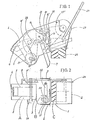
- Figures 1 and 2 show, in elevation and in plan a digging machine placed on the ground.
- a frame is formed by two sheets 1 connected by two clqisons 2 and a protection 3 thus making three compartments A, B, C.
- the compartment A contains a rotating shaft 9 supporting two spade knives each connected to the shaft 9 by means of two leaf springs 5 arranged to let pass, for example, a piece wedged between the knives.
- a curved clod ejector 6 is fixed to the frame 1 and placed inside the spade knives 4 to eject the soil trapped between the spade knives 4.
- one of the two oscillating stops 7, actuated by the operator makes it possible to bear against the groove already made.
- Figure 1 shows one of the two stops which are fixed to the outside of the frame. The one following the machine is pressed against the wall of the groove already made, the one preceding the machine is raised by a value equal to the thickness of the root ball. These stops regulate the thickness of the groove and ensure its continuity.
- the digging machine passes over the entire surface to be turned over.
- the middle compartment B comprises a connection and speed reduction device between the motor 27 and the spade carrier shaft 9.
- the linkage and speed reduction device is composed of a pinion 8 on the shaft 9 driven by a chain and a pulley 8 'actuated by a belt from the motor 27.
- this behavior B there is also a mechanism for 'step by step advance consisting of a shaft 10 fitted with two gears 11 and 11', one of which includes a toothed wheel 12.
- a chain 13 transmits an intermittent rotational movement to a toothed wheel 24 of the machine.
- a gear 14 is supported by an axis 15 on which pivots a crank 16 returned to a position determined by a spring 23 connected by a chain 18 to a crank 19 secured to the shaft 9.
- the chain 18 is tensioned by the spring 23.
- the crank 19 is driven continuously and prints; via chain 18, an oscillating movement at crank 16.
- a freewheel 17 inside the crank 16 allows the shaft 15 to rotate when the crank 16 pivots in a determined direction.
- the crank 16 returns to the rest position under the action of the spring 23, without driving the shaft 15 and thus, without moving the machine.
- the oscillating crank 16 therefore receives its movement from the shaft 9 supporting the spade knife 4.
- the shaft 9 is provided with a crank 19 of which a crank pin 20 is connected by the chain 18 which is wound on a cam 21 of the crank 16 where it is hung.
- a lever 22 is controlled by a rod 26 from a device, not shown, fixed on a handle 25 and can occupy three locked positions: left gear (gear 14 meshes with gear 11), neutral, and right gear (gear 14 meshes with gear 11 ').
- the compartment C is open downwards and houses the toothed wheel 24 which ensures the step-by-step movement and the lifting of the machine.
- the motor 27 suspended by a pivot 27 '.
- a tensioning device (not shown), arranged on the machine 25, the belt between the motor 27 and the pulley 8 ', is tensioned and performs the spade rotation control clutch.
Landscapes
- Life Sciences & Earth Sciences (AREA)
- Engineering & Computer Science (AREA)
- Mechanical Engineering (AREA)
- Soil Sciences (AREA)
- Environmental Sciences (AREA)
- Soil Working Implements (AREA)
- Processing Of Stones Or Stones Resemblance Materials (AREA)
- Measuring Volume Flow (AREA)
- Paper (AREA)
- Massaging Devices (AREA)
Claims (7)
Priority Applications (1)
| Application Number | Priority Date | Filing Date | Title |
|---|---|---|---|
| AT80200706T ATE6568T1 (de) | 1979-08-29 | 1980-07-21 | Motorisierter spaten. |
Applications Claiming Priority (2)
| Application Number | Priority Date | Filing Date | Title |
|---|---|---|---|
| BE878488 | 1979-08-29 | ||
| BE878488 | 1979-08-29 |
Publications (2)
| Publication Number | Publication Date |
|---|---|
| EP0024751A1 EP0024751A1 (de) | 1981-03-11 |
| EP0024751B1 true EP0024751B1 (de) | 1984-03-14 |
Family
ID=3861795
Family Applications (1)
| Application Number | Title | Priority Date | Filing Date |
|---|---|---|---|
| EP80200706A Expired EP0024751B1 (de) | 1979-08-29 | 1980-07-21 | Motorisierter Spaten |
Country Status (3)
| Country | Link |
|---|---|
| EP (1) | EP0024751B1 (de) |
| AT (1) | ATE6568T1 (de) |
| DE (1) | DE3066967D1 (de) |
Family Cites Families (4)
| Publication number | Priority date | Publication date | Assignee | Title |
|---|---|---|---|---|
| DE294457C (de) * | 1914-04-20 | 1916-10-09 | ||
| DE404122C (de) * | 1922-07-26 | 1924-10-14 | Wenzel Hejma Dr | Grabmaschine |
| GB1136561A (en) * | 1965-02-17 | 1968-12-11 | Rotary Hoes Ltd | Improvements in and relating to rotary cultivating machines |
| NL6902245A (de) * | 1969-02-13 | 1970-08-17 |
-
1980
- 1980-07-21 DE DE8080200706T patent/DE3066967D1/de not_active Expired
- 1980-07-21 EP EP80200706A patent/EP0024751B1/de not_active Expired
- 1980-07-21 AT AT80200706T patent/ATE6568T1/de not_active IP Right Cessation
Also Published As
| Publication number | Publication date |
|---|---|
| DE3066967D1 (en) | 1984-04-19 |
| EP0024751A1 (de) | 1981-03-11 |
| ATE6568T1 (de) | 1984-03-15 |
Similar Documents
| Publication | Publication Date | Title |
|---|---|---|
| EP0332552B1 (de) | Verbesserung an Landmaschinen für die Futterernte | |
| EP0147344B1 (de) | Schneidapparat zur Verwendung in der Landwirtschaft, dem Weinbau und der Baumgärtnerei | |
| CA1062920A (fr) | Machine de fenaison pour le fanage et l'andainage | |
| FR2569940A1 (fr) | Faucheuse a moteur comportant un element de manoeuvre orientable | |
| FR2608890A1 (fr) | Tondeuse du type a deplacer devant soi | |
| FR2663189A1 (fr) | Machine de fenaison pour l'andainage, comportant au moins deux roues rateleuses. | |
| EP0206965A1 (de) | Rotationsmäher | |
| FR2823636A1 (fr) | Machine de fenaison, notamment une faucheuse avec un dispositif groupeur d'andains | |
| EP0287487B1 (de) | Bodenbearbeitungsgerät mit quer zum Arbeitsweg rotierenden Wellen | |
| FR2597704A1 (fr) | Materiel de recolte mecanique de fruits. | |
| FR2554308A1 (fr) | Tracteur agricole muni de moyens de commande perfectionnes du dispositif de levage | |
| FR2550413A1 (fr) | Cultivateur rotatif reversible | |
| FR2806871A1 (fr) | Machine de fenaison comportant au moins une roue rateleuse articulee sur un bras porteur | |
| EP0024751A1 (de) | Motorisierter Spaten | |
| BE489222A (de) | ||
| FR2687532A1 (fr) | Appareil de binage mecanique inter plants. | |
| WO1997024025A1 (fr) | Dispositif d'ameublissement du sol | |
| EP0777959A1 (de) | Rasenkanten-Schneider | |
| FR2589033A1 (fr) | Perfectionnement au dispositif de controle automatique de position de l'outil interceps | |
| EP0174223A1 (de) | Landwirtschaftliche Maschine zum Abdecken von Kulturen mit einer Vorrichtung zum Abschneiden der Folien und zum Abdecken der Enden mit Erde | |
| FR2533177A1 (fr) | Tracteur agricole a prises de forces multiples | |
| EP0543688B1 (de) | Silofutterschneider | |
| EP1269826B1 (de) | Heuwerbungsmaschine | |
| FR2722363A1 (fr) | Dispositif de tonte et d'ameublissement du sol et utilisation d'un tel dispositif | |
| EP0064114A1 (de) | Mäh- und Konditioniereinrichtung |
Legal Events
| Date | Code | Title | Description |
|---|---|---|---|
| PUAI | Public reference made under article 153(3) epc to a published international application that has entered the european phase |
Free format text: ORIGINAL CODE: 0009012 |
|
| AK | Designated contracting states |
Designated state(s): AT BE CH DE FR GB IT NL SE |
|
| 17P | Request for examination filed |
Effective date: 19810820 |
|
| GRAA | (expected) grant |
Free format text: ORIGINAL CODE: 0009210 |
|
| AK | Designated contracting states |
Designated state(s): AT BE CH DE FR GB IT LI NL SE |
|
| PG25 | Lapsed in a contracting state [announced via postgrant information from national office to epo] |
Ref country code: SE Free format text: THE PATENT HAS BEEN ANNULLED BY A DECISION OF A NATIONAL AUTHORITY Effective date: 19840314 Ref country code: IT Free format text: LAPSE BECAUSE OF FAILURE TO SUBMIT A TRANSLATION OF THE DESCRIPTION OR TO PAY THE FEE WITHIN THE PRESCRIBED TIME-LIMIT;WARNING: LAPSES OF ITALIAN PATENTS WITH EFFECTIVE DATE BEFORE 2007 MAY HAVE OCCURRED AT ANY TIME BEFORE 2007. THE CORRECT EFFECTIVE DATE MAY BE DIFFERENT FROM THE ONE RECORDED. Effective date: 19840314 Ref country code: AT Effective date: 19840314 |
|
| REF | Corresponds to: |
Ref document number: 6568 Country of ref document: AT Date of ref document: 19840315 Kind code of ref document: T |
|
| REF | Corresponds to: |
Ref document number: 3066967 Country of ref document: DE Date of ref document: 19840419 |
|
| PLBE | No opposition filed within time limit |
Free format text: ORIGINAL CODE: 0009261 |
|
| STAA | Information on the status of an ep patent application or granted ep patent |
Free format text: STATUS: NO OPPOSITION FILED WITHIN TIME LIMIT |
|
| GBPC | Gb: european patent ceased through non-payment of renewal fee | ||
| 26N | No opposition filed | ||
| PG25 | Lapsed in a contracting state [announced via postgrant information from national office to epo] |
Ref country code: GB Effective date: 19881118 |
|
| PGFP | Annual fee paid to national office [announced via postgrant information from national office to epo] |
Ref country code: NL Payment date: 19890731 Year of fee payment: 10 |
|
| PGFP | Annual fee paid to national office [announced via postgrant information from national office to epo] |
Ref country code: CH Payment date: 19900622 Year of fee payment: 11 |
|
| PGFP | Annual fee paid to national office [announced via postgrant information from national office to epo] |
Ref country code: DE Payment date: 19900929 Year of fee payment: 11 |
|
| PG25 | Lapsed in a contracting state [announced via postgrant information from national office to epo] |
Ref country code: NL Effective date: 19910201 |
|
| NLV4 | Nl: lapsed or anulled due to non-payment of the annual fee | ||
| PGFP | Annual fee paid to national office [announced via postgrant information from national office to epo] |
Ref country code: BE Payment date: 19910709 Year of fee payment: 12 |
|
| PG25 | Lapsed in a contracting state [announced via postgrant information from national office to epo] |
Ref country code: LI Effective date: 19910731 Ref country code: CH Effective date: 19910731 |
|
| PGFP | Annual fee paid to national office [announced via postgrant information from national office to epo] |
Ref country code: FR Payment date: 19911227 Year of fee payment: 12 |
|
| REG | Reference to a national code |
Ref country code: CH Ref legal event code: PL |
|
| PG25 | Lapsed in a contracting state [announced via postgrant information from national office to epo] |
Ref country code: DE Effective date: 19920401 |
|
| PG25 | Lapsed in a contracting state [announced via postgrant information from national office to epo] |
Ref country code: BE Effective date: 19920731 |
|
| BERE | Be: lapsed |
Owner name: DURIEUX JULES Effective date: 19920731 |
|
| PG25 | Lapsed in a contracting state [announced via postgrant information from national office to epo] |
Ref country code: FR Effective date: 19930331 |
|
| REG | Reference to a national code |
Ref country code: FR Ref legal event code: ST |