EP0024877B1 - Magnetventil - Google Patents
Magnetventil Download PDFInfo
- Publication number
- EP0024877B1 EP0024877B1 EP19800302872 EP80302872A EP0024877B1 EP 0024877 B1 EP0024877 B1 EP 0024877B1 EP 19800302872 EP19800302872 EP 19800302872 EP 80302872 A EP80302872 A EP 80302872A EP 0024877 B1 EP0024877 B1 EP 0024877B1
- Authority
- EP
- European Patent Office
- Prior art keywords
- armature
- valve
- solenoid
- pole piece
- core tube
- Prior art date
- Legal status (The legal status is an assumption and is not a legal conclusion. Google has not performed a legal analysis and makes no representation as to the accuracy of the status listed.)
- Expired
Links
- 239000012530 fluid Substances 0.000 claims description 12
- 238000006073 displacement reaction Methods 0.000 claims description 6
- 230000004907 flux Effects 0.000 description 5
- 229910000831 Steel Inorganic materials 0.000 description 3
- 239000010959 steel Substances 0.000 description 3
- 239000000696 magnetic material Substances 0.000 description 2
- 239000000463 material Substances 0.000 description 2
- 230000013011 mating Effects 0.000 description 2
- 230000009471 action Effects 0.000 description 1
- 239000000853 adhesive Substances 0.000 description 1
- 230000001070 adhesive effect Effects 0.000 description 1
- 230000000712 assembly Effects 0.000 description 1
- 238000000429 assembly Methods 0.000 description 1
- 150000001875 compounds Chemical class 0.000 description 1
- 238000010276 construction Methods 0.000 description 1
- 230000008878 coupling Effects 0.000 description 1
- 238000010168 coupling process Methods 0.000 description 1
- 238000005859 coupling reaction Methods 0.000 description 1
- 238000013016 damping Methods 0.000 description 1
- 230000007423 decrease Effects 0.000 description 1
- 230000000694 effects Effects 0.000 description 1
- 230000006872 improvement Effects 0.000 description 1
- 238000003780 insertion Methods 0.000 description 1
- 230000037431 insertion Effects 0.000 description 1
- 239000002184 metal Substances 0.000 description 1
- 230000003534 oscillatory effect Effects 0.000 description 1
- 230000002093 peripheral effect Effects 0.000 description 1
- 229920003023 plastic Polymers 0.000 description 1
- 239000004033 plastic Substances 0.000 description 1
- 230000009467 reduction Effects 0.000 description 1
- 230000004044 response Effects 0.000 description 1
- 238000000926 separation method Methods 0.000 description 1
- BFKJFAAPBSQJPD-UHFFFAOYSA-N tetrafluoroethene Chemical group FC(F)=C(F)F BFKJFAAPBSQJPD-UHFFFAOYSA-N 0.000 description 1
Images

Classifications
-
- F—MECHANICAL ENGINEERING; LIGHTING; HEATING; WEAPONS; BLASTING
- F16—ENGINEERING ELEMENTS AND UNITS; GENERAL MEASURES FOR PRODUCING AND MAINTAINING EFFECTIVE FUNCTIONING OF MACHINES OR INSTALLATIONS; THERMAL INSULATION IN GENERAL
- F16K—VALVES; TAPS; COCKS; ACTUATING-FLOATS; DEVICES FOR VENTING OR AERATING
- F16K31/00—Actuating devices; Operating means; Releasing devices
- F16K31/02—Actuating devices; Operating means; Releasing devices electric; magnetic
- F16K31/06—Actuating devices; Operating means; Releasing devices electric; magnetic using a magnet, e.g. diaphragm valves, cutting off by means of a liquid
- F16K31/0644—One-way valve
- F16K31/0655—Lift valves
- F16K31/0658—Armature and valve member being one single element
Definitions
- the invention relates to electrically modulated fluid control valves and to solenoids for such valves.
- An electrically modulated fluid control valve is known from US-A-3,788,579 in which actuation of the valve is accomplished by means of a so-called linear solenoid, with the axial movement of the solenoid armature, relative to a pole piece located inside the surrounding coil structure, being transmitted to a valve member which, in co-operation with an orifice, provides a variable restriction of the flow path through the valve.
- a linear solenoid is known from the prior art in which a push-pin extends from the armature through a central bore in the pole piece and terminates, on the other side of the pole piece, at the valve member. The push-pin and the armature to which the push-pin is secured are supported by two axially spaced ball bearings.
- the present invention aims to provide an electrically modulated fluid control valve having improved operating characteristics and, in particular, improved stability in operation.
- the present invention is based on the appreciation that the use of a solenoid having at least a limited region in which the force-stroke characteristic is positively sloped, and operating the actuating means within that region, gives improved operational stability of a valve actuated by such a solenoid.
- the positively sloping region of the force- slope characteristic is provided by at least one co-operating projection and recess on the facing endfaces of the armature and the pole piece.
- An annular gap separating the adjacent sides of the projections and recesses may be chosen to be sufficiently narrow to divert, over the desired region, a large enough amount of the magnetic flux between pole piece and armature from the axial to the radial direction to obtain the positive slope.
- the solenoid is confined to operate within the positively sloped region by suitable displacement limiting means. These displacement limiting means may, where convenient, be incorporated in the attached valve.
- the slope of the positively sloped region is preferably greater than 10,000 Newton/meter.
- The. accuracy of armature alignment necessary for satisfactory operation in the positive sloping region, particularly in view of the lateral forces experienced by the armature as a result of the radial flux component, is conveniently effected by employing bearings of the kind having a plurality of bearing elements disposed radially about the axis of movement of the armature and individually rotatable about tangential axes.
- bearings of this kind A further effect of using bearings of this kind is to widen the choice of suitable materials to include even magnetic materials and, by permitting the selection of hard materials such as for example steel bearing balls, give better lateral guidance of the armature means combined with improved hysteresis characteristics on account of the reduction in the frictional forces.
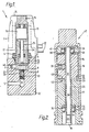
- a hydraulic pressure relief valve 1 embodying the present invention comprises a valve body 2 and a solenoid assembly 3.
- the valve body 2 contains the inlet and outlet fluid passages 5 and 6 which are usually provided with coupling assemblies (not shown) for facilitating connection to the adjoining pipe system.
- the inlet 5 and the outlet 6 are connected by an internal passage 19 which, at its end nearest the orifice chamber 9, incorporates the orifice insert 8.
- the orifice insert 8 has a standard size hexagonal head 21, for ease of mounting of the orifice insert, and a threaded shaft 20 which is secured within a threaded portion of the internal passage 19.
- An axial hole 23 of the orifice insert 8 terminates at its outer end in the small aperture orifice 10.
- the solenoid assembly 3 is contained within a solenoid cover 15 which houses the core tube 14 and the DC coil assembly 13 surrounding the cylindrical core tube 14.
- the core tube is either made altogether of non-magnetic material or includes at least a non-magnetic wall section in the vicinity of the pole piece 17.
- Current proportional to the desired pressure setting is supplied to the solenoid coil 13 via electrical terminals 12.
- the core tube 14 lies centrally within the coil assembly and contains the armature assembly, comprising the cylindrical armature 16 and the push-pin 24, and the pole piece 17 which has an axial through bore 25 through which the push-pin 24 extends to terminate in the anvil 18 opposite the orifice 10.
- the core tube assembly is secured to the valve body 2 by means of a rectangular mounting plate 11 held in place by four mounting screws 4 at the four corners of the mounting plate 11.
- An 0-ring 26, together with a back-up ring, provide a fluid seal preventing hydraulic fluid from escaping past the core tube 14.
- the pole piece 17 is a push fit within the core tube 14 and is held in place by a flanged end section 27 clamped between the core tube and the valve body 2.
- the pole piece 17 has a recessed endface 42, with a peripheral rim 34 extending in an axial direction towards the adjacent endface 43 of the armature 16, whose reduced diameter end portion 32 is of a diameter such as to leave only a small annular gap between its outside surface and the inside surface of the rim 34.
- the armature 16 is secured to the hollow push-pin 24, which extends nearly the whole length of the core tube 14, by means of a set screw 30 and an adhesive compound.
- the outside diameter of the armature 16 is chosen so as to leave a small clearance with the inside of the core tube 14.
- the armature assembly is supported within the core tube by axially spaced ball bearings 35 and 38, each comprising four steel bearing balls 37, 40 disposed radially about the push-pin 24 at right angles to each other and held in place respectively by means of plastics cages 36 and 39.
- the cage 36 is housed in the'pole piece 17, while the cage 39 is supported with the core tube 14 by a metal bearing housing 41 which at the same time provides an endstop for the armature 16.
- the cages 36 and 39 have axially directed grooves along which the bearing balls 37, 40 can move to accommodate the small amount of axial displacement during axial movement of the armature assembly, which in the present valve is of the order of 0.2 mm, while preserving the fixed angular distribution of the bearing balls.
- a small amount of radial clearance between the push-pin 24 and the bearing balls 37 and 40 is necessary, firstly to allow insertion of the open end of the push-pin 24 into the bearing 38 and fitting of the pole piece 17 with bearing 35 over the other end of the push pin 17 when assembling the core tube assembly 47, and secondly to avoid undue friction at the bearings 37 and 40 in operation of the valve 1.
- this radial clearance de-centering of the armature assembly under the action of the radial magnetic flux will still occur, but will be strictly limited on account of the rigidity of the bearing balls.
- Deflection of the armature by the radial flux generated forces will generally be in a direction bisectihg the angle between two neighbouring bearing balls, and during axial movement the push-pin will therefore be in load-transmitting contact with only some of the bearing balls. It has been found in practice that at least four bearing balls -37, 40 per bearing 35, 38 will usually be necessary to achieve the degree of lateral guidance necessary for positively sloped non-linear solenoids. Where desired, the lateral guidance can be further improved by increasing the number of bearing balls in each bearing.
- the lower end of the push-pin 24 accommodates the shank 45 of the anvil 18 which cooperates with the orifice 8 to provide the variable restriction in the flowpath through the valve necessary to control fluid flow therethrough. Abutment of the anvil 18 against the surface 7 of the orifice insert 8 limits the travel of the armature assembly in the downward direction.
- This wet armature design provides additional damping of the armature assembly and in itself contributes to the stability of the valve, particularly if used in conjunction with a restrictor plug 46 in the outlet passage 6.
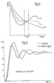
- Curve a of Figure 4 shows a hysteresis loop for a non-linear solenoid constructed as above described and having a positive force-stroke characteristic over the operating range, curve b showing a hysteresis loop for a similarly constructed solenoid but fitted, for experimental purposes, with poly- tetrafluorethylene bearing bushes instead.
- Figure 5 shows the improved step current response of a solenoid having a gradient of 30,000 (curve a) as compared with a conventional linear solenoid having a zero-slope force-stroke characteristic (curve b).
- curve a a linear solenoid having a zero-slope force-stroke characteristic
- curve b a zero-slope force-stroke characteristic
Landscapes
- Engineering & Computer Science (AREA)
- General Engineering & Computer Science (AREA)
- Mechanical Engineering (AREA)
- Magnetically Actuated Valves (AREA)
Claims (7)
Applications Claiming Priority (2)
| Application Number | Priority Date | Filing Date | Title |
|---|---|---|---|
| GB7929432 | 1979-08-23 | ||
| GB7929432 | 1979-08-23 |
Publications (2)
| Publication Number | Publication Date |
|---|---|
| EP0024877A1 EP0024877A1 (de) | 1981-03-11 |
| EP0024877B1 true EP0024877B1 (de) | 1984-03-28 |
Family
ID=10507397
Family Applications (1)
| Application Number | Title | Priority Date | Filing Date |
|---|---|---|---|
| EP19800302872 Expired EP0024877B1 (de) | 1979-08-23 | 1980-08-19 | Magnetventil |
Country Status (3)
| Country | Link |
|---|---|
| EP (1) | EP0024877B1 (de) |
| JP (1) | JPS5631572A (de) |
| DE (1) | DE3067267D1 (de) |
Families Citing this family (5)
| Publication number | Priority date | Publication date | Assignee | Title |
|---|---|---|---|---|
| JPS56109968A (en) * | 1980-02-04 | 1981-08-31 | Fuji Kinzoku Kosaku Kk | Solenoid valve |
| DE3112307A1 (de) * | 1981-03-28 | 1982-10-14 | FAG Kugelfischer Georg Schäfer & Co, 8720 Schweinfurt | Elektromagnetisch betaetigtes ventil |
| GB8603481D0 (en) * | 1986-02-12 | 1986-03-19 | Automotive Prod Plc | Solenoid actuators |
| DE3729222A1 (de) * | 1987-09-02 | 1989-03-16 | Wabco Westinghouse Fahrzeug | Elektromagnetisch betaetigbare ventileinrichtung |
| CN204476550U (zh) * | 2015-03-12 | 2015-07-15 | 大陆汽车电子(芜湖)有限公司 | 一种阀芯总成以及压缩气体旁通阀 |
Family Cites Families (5)
| Publication number | Priority date | Publication date | Assignee | Title |
|---|---|---|---|---|
| DE7142492U (de) * | 1972-02-03 | Binder Magnete Kg | Gleichstrom Hubmagnet | |
| DE847465C (de) * | 1940-12-05 | 1952-08-25 | Wilhelm Binder Fa | Elektromagnet in Topfform mit einem Ankergegenstueck, welches einen Hohlraum aufweist |
| CH405843A (de) * | 1963-11-15 | 1966-01-15 | Eldima Ag | Elektromagnetischer Antriebsmagnet und Verwendung desselben als Bestandteil eines Elektroventils |
| US3788597A (en) * | 1972-05-31 | 1974-01-29 | Yukon Kogyo Co Ltd | Electromagnetic flow controlling valve |
| DE2305124A1 (de) * | 1973-02-02 | 1974-08-08 | Bosch Gmbh Robert | Elektromagnetisch betaetigbares mehrwegeventil |
-
1980
- 1980-08-19 EP EP19800302872 patent/EP0024877B1/de not_active Expired
- 1980-08-19 DE DE8080302872T patent/DE3067267D1/de not_active Expired
- 1980-08-22 JP JP11577280A patent/JPS5631572A/ja active Pending
Also Published As
| Publication number | Publication date |
|---|---|
| DE3067267D1 (en) | 1984-05-03 |
| JPS5631572A (en) | 1981-03-30 |
| EP0024877A1 (de) | 1981-03-11 |
Similar Documents
| Publication | Publication Date | Title |
|---|---|---|
| US5947155A (en) | Linear solenoid valve | |
| US5252939A (en) | Low friction solenoid actuator and valve | |
| US4250922A (en) | Electromagnetically operated control valve | |
| US4655249A (en) | Electromagnetic valve | |
| US5785298A (en) | Proportional solenoid-controlled fluid valve assembly | |
| US4452424A (en) | Electromagnetic linear control valve | |
| US5460201A (en) | Electromechanical servovalve | |
| US4604600A (en) | Solenoid construction and method for making the same | |
| EP2872958B1 (de) | Direkt wirkender elektromagnetaktuator | |
| US6799746B2 (en) | Electromagnet, in particular a proportional magnet for operating a hydraulic valve | |
| US4518938A (en) | Solenoid having low-friction coating internally of the armature sleeve | |
| US4194719A (en) | Hydraulic control valve | |
| US2824574A (en) | Hydraulic servo-valve | |
| CA1223026A (en) | Solenoid construction and method for making the same | |
| JP4820480B2 (ja) | 液圧弁 | |
| US6198369B1 (en) | Proportional actuator for proportional control devices | |
| US3861643A (en) | Saturating magnetic control valve | |
| US4844122A (en) | Electromagnetic valve with two opposed valve seats | |
| JPH0755039B2 (ja) | フォースモータ | |
| KR900003572A (ko) | 솔레노이드 작동 유압제어밸브 | |
| US6182942B1 (en) | Actuator | |
| JP3637404B2 (ja) | リニアソレノイドバルブ | |
| EP0024877A1 (de) | Magnetventil | |
| US4694270A (en) | Electromagnetic proportional actuator | |
| USRE32783E (en) | Solenoid construction and method for making the same |
Legal Events
| Date | Code | Title | Description |
|---|---|---|---|
| PUAI | Public reference made under article 153(3) epc to a published international application that has entered the european phase |
Free format text: ORIGINAL CODE: 0009012 |
|
| AK | Designated contracting states |
Designated state(s): DE FR GB IT |
|
| 17P | Request for examination filed |
Effective date: 19810602 |
|
| ITF | It: translation for a ep patent filed | ||
| GRAA | (expected) grant |
Free format text: ORIGINAL CODE: 0009210 |
|
| AK | Designated contracting states |
Designated state(s): DE FR GB IT |
|
| PG25 | Lapsed in a contracting state [announced via postgrant information from national office to epo] |
Ref country code: FR Free format text: THE PATENT HAS BEEN ANNULLED BY A DECISION OF A NATIONAL AUTHORITY Effective date: 19840328 |
|
| REF | Corresponds to: |
Ref document number: 3067267 Country of ref document: DE Date of ref document: 19840503 |
|
| EN | Fr: translation not filed | ||
| PLBE | No opposition filed within time limit |
Free format text: ORIGINAL CODE: 0009261 |
|
| STAA | Information on the status of an ep patent application or granted ep patent |
Free format text: STATUS: NO OPPOSITION FILED WITHIN TIME LIMIT |
|
| 26N | No opposition filed | ||
| PG25 | Lapsed in a contracting state [announced via postgrant information from national office to epo] |
Ref country code: DE Effective date: 19850501 |
|
| GBPC | Gb: european patent ceased through non-payment of renewal fee | ||
| PG25 | Lapsed in a contracting state [announced via postgrant information from national office to epo] |
Ref country code: GB Effective date: 19881118 |