EP0025213A2 - Ultraschallgerät zum Nachweis von Rissen - Google Patents
Ultraschallgerät zum Nachweis von Rissen Download PDFInfo
- Publication number
- EP0025213A2 EP0025213A2 EP80105249A EP80105249A EP0025213A2 EP 0025213 A2 EP0025213 A2 EP 0025213A2 EP 80105249 A EP80105249 A EP 80105249A EP 80105249 A EP80105249 A EP 80105249A EP 0025213 A2 EP0025213 A2 EP 0025213A2
- Authority
- EP
- European Patent Office
- Prior art keywords
- probe
- carriage
- flaw detector
- ultrasonic flaw
- probe holder
- Prior art date
- Legal status (The legal status is an assumption and is not a legal conclusion. Google has not performed a legal analysis and makes no representation as to the accuracy of the status listed.)
- Granted
Links
Images



Classifications
-
- G—PHYSICS
- G01—MEASURING; TESTING
- G01N—INVESTIGATING OR ANALYSING MATERIALS BY DETERMINING THEIR CHEMICAL OR PHYSICAL PROPERTIES
- G01N29/00—Investigating or analysing materials by the use of ultrasonic, sonic or infrasonic waves; Visualisation of the interior of objects by transmitting ultrasonic or sonic waves through the object
- G01N29/22—Details, e.g. general constructional or apparatus details
- G01N29/26—Arrangements for orientation or scanning by relative movement of the head and the sensor
- G01N29/265—Arrangements for orientation or scanning by relative movement of the head and the sensor by moving the sensor relative to a stationary material
-
- G—PHYSICS
- G01—MEASURING; TESTING
- G01N—INVESTIGATING OR ANALYSING MATERIALS BY DETERMINING THEIR CHEMICAL OR PHYSICAL PROPERTIES
- G01N2291/00—Indexing codes associated with group G01N29/00
- G01N2291/02—Indexing codes associated with the analysed material
- G01N2291/028—Material parameters
- G01N2291/02854—Length, thickness
Definitions
- This invention relates to an ultrasonic flaw detector, and more particularly to an ultrasonic flaw detector which can satisfactorily perform also the inspection of a curved surface portion such as it appears in a bent piping.
- the detector comprises a carriage travelling on a guide rail mounted on a pipe, a guide rod mounted on the carriage and extending in the axial direction of the pipe, an inspection arm mounted so as to move along the guide rod and extending perpendicularly to the surface of the pipe, and a probe mounted on the end of the inspection arm so as to contact with the surface to be inspected .
- the prove follows well the surface of a straight pipe shown in Figure 1 of the above mentioned document, through the peripheral movement of the carriage as well as the guide rod, the axial movement of the inspection arm, and the movement of the prove perpendicular to the surface to be inspected of the pipe.
- the ultrasonic flaw detector is employed to inspect the curved surface part of a bent pipe, it does not seem thatthe probe follows the curved surface well enough.
- An object of the invention is to provide an ultrasonic flaw detector, in which a probe can follow satisfactorily a curved surface such as appears in a bent pipe.
- Another object of the invention is to provide an ultrasonic flaw detector, wherein a probe can move to cover all the surface to be inspected including a curved surface of a bent pipe, and which can trace the track of the probe even if it is operated manually.
- Still further another object of the invention is to provide an ultrasonic flaw detector which can detect flaws in the curved surface such as appeared in a bent pipe without taking a large area for installing the detector on the bent pipe.
- the invention resides in an ultrasonic flaw detector comprising a carriage travelling on a guide rail, a guide_arm extending in a direction traversing the travel direction of the carriage and mounted on the carriage swingably on a plane traverse to the travel direction, a probe holder slidably mounted on the guide arm and extending at a fixed angle in the plane on which the guide arm swings, and probe held turnably by the probe holder so that the probe follow a curved face to be detected .
- the ultrasonic flaw detector 1 comprises a carriage 3, a guide arm 5 supported by the carriage 3 to move along with the carriage 3, a probe holder 7 mounted slidably on the guide arm 5, and a probe 9.
- the carriage 3 is fitted on a guide rail 11 so as to travel thereon.
- the guide rail 11 is mounted coaxially on a pipe 2 to be inspected, and has a guide groove portion 13, a rack 15, and a supporting portion 17, each formed thereon.
- the carriage 3 is provided with front rollers 21 fitted in the groove 13, back rollers 23 pressing the backside of the groove portion 13, which back rollers 23 each are mounted rotatably on brackets 37 .
- a plurality of pairs of the rollers 21 and 23 sandwitch the guide rail 11 so that the carriage 3 can not be disconnected from the guide rail 11
- the carriage 3 has a housing 25 somewhat extending circumferentially and supporting thereon the guide arm 5 as previously stated, and a driving apparatus 27 in the housing 25 .
- the driving apparatus 27 comprises a motor 29, a safety device 31 connected to the motor 29 by gear means, a reduction gears 33 including a worm gearing mechanically connected to the safety device 31 by gear means, and a pinion 35 mesched with the rack 15 of the guide rail 11 .
- the safety device 31 includes a shaft with a flange 32, and a gear 34 pressed by a spring and brought into a frictional engagement with the flange 32, and it is made so that tbe.gear 34 idles and the rotation of the motor 29 is not transmitted to the pinion 35 when the pinion 35 recieves a force larger than a frictional force made between the gear 34 and the flange 32.
- a rotary encorder 36 is connected to the pinion 35 through gear means tomake signals corresponding to travelling distance of the carriage 3 .
- the back roller 23 is mounted on the bracket 37.
- the bracket 37 is fitted in a groove 38 made in the side portion of the housing 25 and separably secured thereto by screw means .
- the carriage 3 can run on the guide rail 11 according to the rotation of the motor 29 and be stopped at any positions .
- the guide arm 5 comprises two rods 39, 41 arranged in parallel to each other, a tie member 43 tieing the rods 39, 41 at one ends of the rods 39, 41, and a L-shaped connecting member 45 which connects the rods 39, 41 to the carriage 3.
- the L-shaped connecting member 45 which secures thereto the end portions of the rods 39, 41 by bolt and nut means 50, is mounted rotatably on a bracket 47 secured to the side of the carriage housing 25 by a pin 49, whereby the guide arm 5 can be rotated or swinged around the pin 49 in a plane perpendicular to the travelling direction of the carriage 3 .
- the guide rods 39, 41 are arranged with horizontal and vertical spacings to each other when the carriage 3 is disposed horizontally.
- the guide arm 5 arranged in such that manner is mechanically stable and minimized in its deformation even when a rotating moment is applied tothe guide arm 5.
- the probe holder 7 slidably mounted on the guide arm 5 through ball bearings (not shown) will be described more in detail referring to Figures 4 and 5.
- the probe holder 7 comprises a holder housing 51 and a probe holding unit 52 .
- the holder housing 51 has an upper arm portion 53 slidably mounted on the guide arm 5, and a lower arm portion 55 supporting the probe holding unit 52.
- the probe holding unit 52 comprises a ring-shaped member 61 embracing the periphery of the probe 9, a U-shaped member 65 connected to the ring-shaped member 61 and a rotary shaft 67, one end of which is secured to the ring-shaped member 61 and the other end is rotatably supported by the lower arm portion 55 of the holder housing 51 .
- the lower arm portion 55 has a pair of bearings 59.
- the rotary shaft 67 of the arm holding unit 52 is inserted in the bearings 59, and it has a flange portion 68 atthe intermediate portion which is sandwitched by a pair of springs 72 inserted in the lower arm portion 55 through spring holders 70, whereby the axial movement of the rotary shaft 67 is restricted while it is rotated freely .
- the probe 9 is fitted in the ring-shaped member 61 and secured thereto by a screw means 61 .
- the probe 9, supported by the probe holder 7 in such a manner can be moved freely on the guide arm5 5 by a manual operation.
- the probe 9 can be rotated around the pin 63 and the rotary shaft 67 which are crossed at a right angle on a plane a little spaced from a surface to be inspected .
- a position of the probe holder 7 on the guide arm 5 is measured by a rotary encorder 71 .
- the rotary encorder 71 is fastened to the holder housing 51 through a mounting member 73.
- the rotary e ncorder 71 has a rotary shaft on which a pinion 75 is secured .
- the pinion 75 is meshed with a rack 40 formed on one 39 of the guide rods of the arm 5, whereby movement of the probe holder 7 is transmitted to the rotary encorder 71
- a push button 77 for driving the motor 29 is provided on an upper portion 76 of a projection of the ring-shaped member 61 .
- the probe 9 moves circumferentially by one pitch which is, for example, 6 mm corresponding to about 70% of the width of a surface to be inspected by sweeping the probe 9 one .
- a movement of the motor 29 is transmitted to the pinion 35 through the safety device 31 , the gears 33.
- the movement of the pinion 35 causes the carriage 3 to move circumferentially on the guide rail 11 by a distance corresponding to the above mentioned one pitch.
- the movement of the carriage 3 is transmitted to the rotary encorder 37, and the rotary encorder 37 measures a circumferential running or travelling distance of the probe 9.
- An axial movement of the probe 9 on the pipe 2 is effected by manually moving the probe holder 7 on the guide arm 5 ..
- the axial movement of the probe 9 is transmitted to the rotary encorder 71 through the rack 40 of the guide arm 5 and the pinion 75 meshed therewith whereby the distance corresponding to the axial movement or shift is measured by the rotary encorder 71 .
- the ultrasonic flaw detector 1 inspects a welding portion 4 and a portion adjacent thereto as shown in Figure 1 , first, the guide rail 11 is mounted on the pipe 2 adjacent to a region to be inspected, that is, adjacent to the welding portion. Next, the ultrasonic flaw detector 1 is installed on the guide rail 11 , whereby it is ready for operation.
- the probe 9 is positioned at a proper circumferential.pasition of the pipe 2 by travelling circumferentially the carriage 3 with the push button 77 being operated . Under this condition, an operator moves axially the probe holder 7 to inspect the tube 2 while pressing the probe 9 on the surface to be inspected. After that, the carriage 3 is transfered by the motor 29 by one pitch, with the push button 77 being pushed.
- the probe 9 is moved axially as abovementioned. All the surface to be inspected is inspected by repeating the abovementioned operations .
- the probe 9 follows well enough even the curve surface of'a bent pipe.
- the guide arm 5 supporting the probe holder 7 is swinged or rotated about the pin 47 and the probe 9 also is swinged or rotated about the rotary shaft 67, according to the curvature of the curved surface, whereby the probe 9 faces alwasy the surface to be inspected.
- the probe 9 is moved in the peripheral direction, even if the carriage 3 is moved strictly circularly around the bent pipe, the probe 9 is not moved on the same track . Therefore the probe 9 follows the curved surface to be inspected through swinging movement of the guide arm 5 about the pin 47, swinging movements of the probe 9 about the rotary shaft 67 and the pin 63 .
- Peripheral and axial running distances of the probe 9 are measured by the rotary encorders each rotating according to the movements of the carriage 3 and the probe holder 7 as abovementioned .
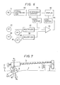
- Pulses generated from the rotary encorder 71 pass through a phase discriminator circuit 80 for deciding a direction, and- are thereafter counted by a reversible counter 81 .
- a potentiometer 85 for measuring the angle ⁇ 1 is mounted on the housing 51 .
- a potentiometer 88 for measuring the angle ⁇ 2 (inclination of the arm) is mounted on the carriage 3 for measuring the inclination.
- the measurement signal of the potentiometer 85 is transmitted to a multiplier unit 87 .
- the multiplier unit 87 receives a signal from a potentiometer 85 in which the length L 1 between the pin 67 and the lower face of the probe 9 is set.
- the operation of L 1 sin ⁇ is executed in the multiplier unit 87 .
- the measurement signal of the potentiometer 88 and a signal from a potentiometer 89 for setting the length L 2 between the arm 5 and the pin 67 are applied to a multiplier unit 90 to execute the operation of L 2 sin ⁇ 2 .
- the signals from the multiplier units 87 and 90 and also a signal obtained by converting an output of the reversible counter 81 by means of a converter 83 are respectively applied to an adder unit 91 and added therein, whereby the exact position of the probe 9 can be evaluated.
- an output from the adder unit 91 is displayed on a coordinate value display unit 82 together with the circumferential position measured by the rotary encorder 36 . It is also possible that, without making the correction as stated above, the signal of the reversible counter 81 is transmitted directly to the coordinate value display unit 82 through the change-over of a switch .
- FIG. 8 Another embodiment of the ultrasonic flaw detector according to the invention will be described hereinafter in detail, referring to Figure 8.
- This embodiment differs from the abovementioned embodiment mainly in a construction of a probe holder 7A , the probe holder 7A is suitable for axially transferring the probe 9 one pitch by one pitch by manual operation.
- a holder housing 51A moving slidably on the guide rods 39, 41 of the guide arm 5 holds the probe 9 in the same manner as in Figure 4.
- a shaft 95 with knob is rotatably mounted on both the holder housing 51A and a bearing.supporter 96 fixed to the holder housing 51 through bearings 97, and it is provided with a pinion 98, the rotation of which is transmitted to the rotary encorder 7t through gears to measure a running distance of the probe holder 7A on the guide arm 5.
- a shifter 94 is provided on the end portion of the shaft 95 with the knob.
- the shifter 94 comprises a disc 99 fixed to the end of the shaft 95 and a ball holder 100.
- the disc 99 has a plurality of ball receiving grooves 101 formed therein, two adjacent grooves determine an axial running pitch of the probe 9, for example 6 mm.
- the ball holder 100 which is cylindrical, is rotatably fitted on the knob shaft 95 .
- the ball holder 100 is provided one hole which is spaced from the axis thereof and extends axially. In this hole, a ball 106 is inserted loosely, and pressed on the disk 99 by a spring 102.
- the ball holder 100 furthermore, has another hole 110, formed perpendicularly to the axis of the ball holder 100, and receiving a pin 103 which is inserted in a pin holder 104 secured to the probe holder 51A .
- the pin 103 has a knob 105 fixed to one end thereof, and it is pressed by a spring 107 so as to fit in the hole 110 of the ball holder 100.
- the knob shaft 95 when the knob shaft 95 is rotated by manual operation, the ball 106 goes out from the groove 101 , and enter the adjacent next groove 101 , whereby the probe holder 7A is shifted by one pitch, and the distance shifted is measured by the rotary encorder 71 .
- the probe 9 or the probe holder 7A can be shifted precisely one pitch by one pitch by repeating such operation.
- the knob 105 When it is intented to release the probe holder 7A from the shifter 94, the knob 105 is pulled leftwards on Figure 8 to take off the pin 103 from the hole 110 by about the length of a pin 111 , and then rotated by a certain angle, whereby the pin 111 comes out of a groove- 112 formed in the knob 105 so that the pin 103 is kept falled off from the hole 110, and the probe holder 7A can be freely shifted .
- the probe holder 7A with the shifter 94 for example in the case of inspection of a tube, of which a portion to be inspected is shorter in its axial length and longer in its circumference, is shifted by one pitch by the manual operation as abovementioned as for axial transfer of the ultrasonic flaw detector 1 , while circumferential shift of the detector 1 is effected by running the motor 29, with the probe 9 being manually pressed on the portion to be detected .
- By repeating the axial shift and the circumferential transfer all the portion to be inspected is inspected effectively.
- the shifter can be replaced for a motor-driven device including a motor.
- the circumferential transfer of the probe 9 is carried out by running circumferentially the carriage 3.
- the operation is effected while pressing the probe 9 on the surface to be inspected an effective inspection can be carried out if running speed changes in proportion to force applied on the push button 77 operating the motor 29.
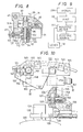
- a direct current motor 29A for the motor 29 may be used, and there are provided a potentiometer 117 changing electric currents fed to the motor 29A , and an amplifier 116 for amplifying the electric currents, as shown in Figure 9.
- the potentiometer 117 as shown in Figure 4, is mounted on the holder housing 51, and actuated by a lever 118 mounted on a shaft 67.
- the shaft 67 compresses the spring 72 and the lever 118 actuates the potentiometer 117 whereby the motor 29A is driven .
- a s the push button 77 is further pushed, the resistance of the potentiometer 117 changes to increase electric current to the motor 29A whereby the running speed increases.
- the running speed of the carriage 3 is freely changed by an manual operation, and effective inspection can be achieved.
- a carriage 132 or a circumferentially driving apparatus is provided with a plurality of guide rollers 145, 146 and a gear 150.
- the guide rollers 145 sandwitch an annular guide rail 131 up and down, and the guide rollers 146 sandwitch the guide rail 131 from opposite sides, so that the carriage 132 can travel on and along the guide rail 131 .
- the gear 150 is meshed with rack 147 formed on the guide rail 131 .
- the gear 150 is driven by a motor 152 through a worm 153 and gears 148, 149. Rotation of the gear 150 allow the carriage to move circumferentially on the guide rail 131 .
- Rotation of the motor 152 is transmitted to a rotary encorder for measuring a circumferentially travelling amount of the carriage 132 through the gear 148, 149 and a gear 154.
- a probe holder 134 or axially driving apparatus which has a shifter as previously described in Figure 8 is mounted slidably on a guide arm.
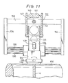
- the arm as best shown in Figure 11 , comprises an upper rod 155 and two lower rods 136 each extending in a traversing direction of the travel direction of the carriage 132, and a pair of trying members 154 for typing ends of the rods 155, 136.
- the upper rod 155 is supported by the carriage 132 with a pin 140 fired to the carriage so that the arm can swing in a plane traversing the travel direction of the carriage 132.
- the prove holder 134 is slidably mounted on the lower rods 136, and has a rotary encorder 135, to which axial movement of the probe holder 134 is trasmitted through a pinion 156 meshed with a rack formed on the rod 136, gears 157, 158.
- a rotary shaft 139 is rotalably mounted, extending in the travel direction of the carriage 132.
- a probe 124 is fitted in a probe mounting member 138 which is rotatably connected to the rotary shaft 139 by a pin 159 so that the probe can be turnable about two axes as shown by arrows in Figures 10 and 11 .
- a knob 137 of the shifter is for shifting the probe 124 intermittently with interval of one pitch. The pitch is taken in such a way that two adjacent racks of the probe 124 is overlapped partially.
- the annular rail 131 is mounted on a pipings 130 to be inspected through three (3) poles 150 with spacing adjustable devices 153.
- the poles each have a roller 151, whereby the guide rail 131 can be transferred circumferentially.
- the probe 124 is gripped by an operation hand, and shifted manually between the tying member 154 and the opposite tying member 154.
- the probe 124 is held so as to be easily inclined axially and circumferentially so that the probe 124 follows well enough and.contact with even a curved and complicated surface of an object to be inspected, and can emit proper ultrasonic beam on the surface to-be inspected.
- the carriage 132 is transferred circumferentially on the rail 131 by the motor 152.
- Axial and circumferential movements are automatically measured by the rotary encorder 135 for measuring an axially moving amount of distance and the rotary encorder 133 for measuring a circumferentially moving amount of distance, and signals corresponding to the moving amounts are sent to a display and a control apparatus, wherein tracks of the probe can be automatically displayed.
- the results of the ultrasonic flaw detection is recorded by signals from the probe 124.
- travelling range is limitted to betweeen one of the pole 150 and the adjacent pole 150, but the rail 131 is constructed so as to move circumferentially, whereby the ultrasonic flaw detection can be effected over the abovementioned range.
- positioning of the probe 124 after the movement of the annular rail 131 a precise position can be detected by setting the probe 124 on the marked points to reset the position display device after marking several points on a circle of the object to be detected, and setting the probe 134 on the marked points .
- the ultrasonic flaw detector for pipings is constructed in such a way that the probe 124 can be inclined a axially and circumferentially according to the surface to be detected to contact with the surface, therefore inspection can be effected on welding portions in straight pipes, elbs, valves, pumps, and welding portion formed by various combinations of them, and its application range is increased. Furthermore, since all the position detection and record can be made automatic, skilled inspectors are exposed less to radioactives in the case of inspection of radioactive pipings, and a great reduction of time necessary for analyzing inspecting results which results in a great labor saving can be effected where the position detection and record are directed to computors to treat with them .
- the probe holder is described as manually operated, however the probe holder may be replaced for a motor-driven probe holder whereby complete automatic program can be carried out.
Landscapes
- Physics & Mathematics (AREA)
- Health & Medical Sciences (AREA)
- Life Sciences & Earth Sciences (AREA)
- Chemical & Material Sciences (AREA)
- Analytical Chemistry (AREA)
- Biochemistry (AREA)
- General Health & Medical Sciences (AREA)
- General Physics & Mathematics (AREA)
- Immunology (AREA)
- Pathology (AREA)
- Investigating Or Analyzing Materials By The Use Of Ultrasonic Waves (AREA)
Applications Claiming Priority (2)
| Application Number | Priority Date | Filing Date | Title |
|---|---|---|---|
| JP114252/79 | 1979-09-07 | ||
| JP11425279A JPS5639459A (en) | 1979-09-07 | 1979-09-07 | Supersonic flaw detector |
Publications (3)
| Publication Number | Publication Date |
|---|---|
| EP0025213A2 true EP0025213A2 (de) | 1981-03-18 |
| EP0025213A3 EP0025213A3 (en) | 1981-10-14 |
| EP0025213B1 EP0025213B1 (de) | 1985-02-13 |
Family
ID=14633110
Family Applications (1)
| Application Number | Title | Priority Date | Filing Date |
|---|---|---|---|
| EP80105249A Expired EP0025213B1 (de) | 1979-09-07 | 1980-09-03 | Ultraschallgerät zum Nachweis von Rissen |
Country Status (5)
| Country | Link |
|---|---|
| US (1) | US4383448A (de) |
| EP (1) | EP0025213B1 (de) |
| JP (1) | JPS5639459A (de) |
| CA (1) | CA1135828A (de) |
| DE (1) | DE3070162D1 (de) |
Cited By (6)
| Publication number | Priority date | Publication date | Assignee | Title |
|---|---|---|---|---|
| EP0134534A1 (de) * | 1983-08-16 | 1985-03-20 | Siemens Aktiengesellschaft | Aussen an einem Rohr ansetzbarer Prüfmanipulator |
| DE3337635A1 (de) * | 1983-10-15 | 1985-04-25 | M.A.N. Maschinenfabrik Augsburg-Nürnberg AG, 8500 Nürnberg | Manipulator zur pruefung von rohrleitungs-kruemmerrund- und -laengsschweissnaehten in kernkraftanlagen |
| EP0207338A3 (de) * | 1985-07-05 | 1989-08-30 | Thyssen Industrie Ag | Oberflächenprüfeinrichtung |
| EP0580311A1 (de) * | 1992-07-18 | 1994-01-26 | Rolls-Royce And Associates Limited | Vorrichtung zum Nachweis von Fehlern |
| CN109341577A (zh) * | 2018-10-19 | 2019-02-15 | 北京市机械施工有限公司 | 一种钢管加工椭圆度检测装置 |
| CN114280151A (zh) * | 2021-12-28 | 2022-04-05 | 河北大唐国际丰宁风电有限责任公司 | 伸缩式超声波探伤装置 |
Families Citing this family (28)
| Publication number | Priority date | Publication date | Assignee | Title |
|---|---|---|---|---|
| US4586379A (en) * | 1984-09-28 | 1986-05-06 | Virginia Corporation Of Richmond | Ultrasonic pipe inspection system |
| JPH0664028B2 (ja) * | 1984-12-27 | 1994-08-22 | 株式会社日立製作所 | 超音波探傷方法 |
| JPH04126158U (ja) * | 1991-04-30 | 1992-11-17 | 石川島播磨重工業株式会社 | 配管探傷装置 |
| WO1994001766A1 (en) * | 1992-07-14 | 1994-01-20 | Sierra Matrix, Inc. | Hands-free ultrasonic test view (hf-utv) |
| EP0718853A1 (de) * | 1994-12-21 | 1996-06-26 | ABB Reaktor GmbH | Verfahren und Einrichtung zum Ultraschallprüfen eines nur über einen Spalt zugänglichen Bauelementes |
| US5710378A (en) * | 1995-03-31 | 1998-01-20 | General Electric Company | Inspection tool for detecting cracks in jet pump beams of boiling water reactor |
| BR0309842A (pt) * | 2002-05-08 | 2005-03-15 | Graham Packaging Co | Tubo vertical em duas peças que pode ser comprimido |
| US10308265B2 (en) | 2006-03-20 | 2019-06-04 | Ge Global Sourcing Llc | Vehicle control system and method |
| US9733625B2 (en) | 2006-03-20 | 2017-08-15 | General Electric Company | Trip optimization system and method for a train |
| US9950722B2 (en) | 2003-01-06 | 2018-04-24 | General Electric Company | System and method for vehicle control |
| CN100342231C (zh) * | 2003-12-09 | 2007-10-10 | 北京有色金属研究总院 | 浮箱摆式跟踪轮机构 |
| US9956974B2 (en) | 2004-07-23 | 2018-05-01 | General Electric Company | Vehicle consist configuration control |
| US9689681B2 (en) | 2014-08-12 | 2017-06-27 | General Electric Company | System and method for vehicle operation |
| US9828010B2 (en) | 2006-03-20 | 2017-11-28 | General Electric Company | System, method and computer software code for determining a mission plan for a powered system using signal aspect information |
| US7644618B2 (en) * | 2007-10-26 | 2010-01-12 | The Boeing Company | Apparatus and method for nondestructive inspection of parts |
| JP5198112B2 (ja) * | 2008-03-26 | 2013-05-15 | 旭化成ケミカルズ株式会社 | 配管の検査装置及びその検査方法 |
| US8914171B2 (en) | 2012-11-21 | 2014-12-16 | General Electric Company | Route examining system and method |
| US20110000302A1 (en) * | 2009-07-01 | 2011-01-06 | Xavier Georges Jose Deleye | Method for ultrasonic inspecting a substantially circumferential weld and an apparatus for carrying out such method |
| CN102830178A (zh) * | 2012-08-09 | 2012-12-19 | 江苏三合声源超声波科技有限公司 | 超声波探伤用支架 |
| WO2014026091A2 (en) | 2012-08-10 | 2014-02-13 | General Electric Company | Route examining system and method |
| US9702715B2 (en) | 2012-10-17 | 2017-07-11 | General Electric Company | Distributed energy management system and method for a vehicle system |
| GB2516287B (en) * | 2013-07-18 | 2018-06-20 | Bae Systems Plc | Material inspection device |
| WO2015008046A1 (en) | 2013-07-18 | 2015-01-22 | Bae Systems Plc | Material inspection device |
| US9255913B2 (en) | 2013-07-31 | 2016-02-09 | General Electric Company | System and method for acoustically identifying damaged sections of a route |
| EP3775829A4 (de) * | 2018-04-27 | 2021-12-22 | Shawcor Ltd. | Ultraschallscanner zur verwendung in rohrleitungen |
| CN109752460B (zh) * | 2019-01-16 | 2022-06-14 | 中国人民解放军陆军装甲兵学院 | 一种深长孔管类件可视化超声无损检测装置及方法 |
| CN110988131B (zh) * | 2019-12-19 | 2022-03-25 | 宁波川原精工机械有限公司 | 一种轴承检测用超声表面探伤装置 |
| CN111379956B (zh) * | 2020-03-26 | 2021-03-05 | 湖北楚天卓越工程技术有限公司 | 建筑用管道表面质量自动检测机器人及使用方法 |
Family Cites Families (10)
| Publication number | Priority date | Publication date | Assignee | Title |
|---|---|---|---|---|
| DE2153397C3 (de) * | 1971-10-27 | 1974-11-21 | Maschinenfabrik Augsburg-Nuernberg Ag, 8900 Augsburg | Halterung fur Ultraschall Prüf köpfe zum Prüfen von unregelmäßig ge formten Werkstucksteilen |
| US3934357A (en) * | 1973-08-10 | 1976-01-27 | Couvillion Claude C | Teaching method and apparatus |
| US3921440A (en) * | 1975-01-02 | 1975-11-25 | Air Prod & Chem | Ultrasonic pipe testing system |
| US3934457A (en) * | 1975-01-13 | 1976-01-27 | General Electric Company | Vessel nozzle inspection apparatus |
| GB1507272A (en) * | 1975-02-13 | 1978-04-12 | Graenges Oxeloesunds Jaernverk | Device for non-destructive testing of rolled steel plate and the like |
| DE2609541C3 (de) * | 1976-03-08 | 1979-02-01 | Kraftwerk Union Ag, 4330 Muelheim | Einrichtung zur Ultraschallprüfung von Rohrleitungen, insbesondere der Hauptkühlmittelleitung von Kernreaktoranlagen |
| DE2655179A1 (de) * | 1976-12-06 | 1978-06-08 | Kraftwerk Union Ag | Pruefkopfhalterung an einem pruefsystemtraeger, vorzugsweise fuer ultraschall-pruefkoepfe |
| DE2726612C3 (de) * | 1977-06-13 | 1984-06-14 | Kraftwerk Union AG, 4330 Mülheim | Prüfmanipulator zur Außenprüfung von Rohrleitungen, vorzugsweise zum Ultraschall-Prüfen bei Reaktordruckbehältern |
| JPS5441789A (en) * | 1977-09-09 | 1979-04-03 | Hitachi Ltd | Ultrasonic inspector |
| JPS5518987A (en) * | 1978-07-28 | 1980-02-09 | Hitachi Ltd | Ultrasonic flaw detecting drive device |
-
1979
- 1979-09-07 JP JP11425279A patent/JPS5639459A/ja active Pending
-
1980
- 1980-09-03 EP EP80105249A patent/EP0025213B1/de not_active Expired
- 1980-09-03 DE DE8080105249T patent/DE3070162D1/de not_active Expired
- 1980-09-05 US US06/184,376 patent/US4383448A/en not_active Expired - Lifetime
- 1980-09-08 CA CA000359808A patent/CA1135828A/en not_active Expired
Cited By (8)
| Publication number | Priority date | Publication date | Assignee | Title |
|---|---|---|---|---|
| EP0134534A1 (de) * | 1983-08-16 | 1985-03-20 | Siemens Aktiengesellschaft | Aussen an einem Rohr ansetzbarer Prüfmanipulator |
| DE3337635A1 (de) * | 1983-10-15 | 1985-04-25 | M.A.N. Maschinenfabrik Augsburg-Nürnberg AG, 8500 Nürnberg | Manipulator zur pruefung von rohrleitungs-kruemmerrund- und -laengsschweissnaehten in kernkraftanlagen |
| EP0207338A3 (de) * | 1985-07-05 | 1989-08-30 | Thyssen Industrie Ag | Oberflächenprüfeinrichtung |
| EP0580311A1 (de) * | 1992-07-18 | 1994-01-26 | Rolls-Royce And Associates Limited | Vorrichtung zum Nachweis von Fehlern |
| US5571968A (en) * | 1992-07-18 | 1996-11-05 | Rolls-Royce And Associates, Limited | Apparatus for mounting a plurality of ultrasonic probes for movement in specified directions for detecting defects in a body |
| CN109341577A (zh) * | 2018-10-19 | 2019-02-15 | 北京市机械施工有限公司 | 一种钢管加工椭圆度检测装置 |
| CN114280151A (zh) * | 2021-12-28 | 2022-04-05 | 河北大唐国际丰宁风电有限责任公司 | 伸缩式超声波探伤装置 |
| CN114280151B (zh) * | 2021-12-28 | 2024-04-16 | 河北大唐国际丰宁风电有限责任公司 | 伸缩式超声波探伤装置 |
Also Published As
| Publication number | Publication date |
|---|---|
| JPS5639459A (en) | 1981-04-15 |
| CA1135828A (en) | 1982-11-16 |
| DE3070162D1 (en) | 1985-03-28 |
| EP0025213A3 (en) | 1981-10-14 |
| US4383448A (en) | 1983-05-17 |
| EP0025213B1 (de) | 1985-02-13 |
Similar Documents
| Publication | Publication Date | Title |
|---|---|---|
| EP0025213A2 (de) | Ultraschallgerät zum Nachweis von Rissen | |
| CA1206278A (en) | Fluoroscopic examination of pipe girth welds | |
| JPS60252260A (ja) | 円管スクレ−パ | |
| GB2157930A (en) | Radiography apparatus | |
| JPS61176849A (ja) | 配管群用自動超音波探傷装置 | |
| JPH0634090B2 (ja) | セル内点検装置の走行装置 | |
| JPS6367137B2 (de) | ||
| JPS6230953A (ja) | 配管検査装置 | |
| JPH0664028B2 (ja) | 超音波探傷方法 | |
| JPS6239765A (ja) | 自動超音波深傷装置 | |
| JPH08338896A (ja) | ノズルの超音波探傷装置 | |
| JPS61223510A (ja) | 探触子位置検出方式 | |
| KR930010452B1 (ko) | 관로(管路)의 검사장치 | |
| JPH0338699Y2 (de) | ||
| JP2004101268A (ja) | 炉底部作業装置および作業方法 | |
| CN221848940U (zh) | 一种用于机器人焊接稳定性的测定系统 | |
| JPH02231562A (ja) | 配管非破壊診断装置 | |
| JPH07191001A (ja) | 超音波探傷装置 | |
| JPS60228957A (ja) | 配管用超音波探傷子保持装置 | |
| JP2683066B2 (ja) | 電縫管の内面ビード切削形状測定装置 | |
| JPS6253769B2 (de) | ||
| CN107271552A (zh) | 一种自吸式小径管对接焊缝超声检测自动扫查器 | |
| JPH1026511A (ja) | 無軌道式検査装置及びその検査位置の検出方法 | |
| KR830002286Y1 (ko) | 와전류에 의해 금속판중의 결함을 검출하는 장치 | |
| JPH0197856A (ja) | 超音波探傷装置 |
Legal Events
| Date | Code | Title | Description |
|---|---|---|---|
| PUAI | Public reference made under article 153(3) epc to a published international application that has entered the european phase |
Free format text: ORIGINAL CODE: 0009012 |
|
| AK | Designated contracting states |
Designated state(s): DE FR SE |
|
| PUAL | Search report despatched |
Free format text: ORIGINAL CODE: 0009013 |
|
| AK | Designated contracting states |
Designated state(s): DE FR SE |
|
| 17P | Request for examination filed |
Effective date: 19811007 |
|
| GRAA | (expected) grant |
Free format text: ORIGINAL CODE: 0009210 |
|
| AK | Designated contracting states |
Designated state(s): DE FR SE |
|
| REF | Corresponds to: |
Ref document number: 3070162 Country of ref document: DE Date of ref document: 19850328 |
|
| ET | Fr: translation filed | ||
| PLBI | Opposition filed |
Free format text: ORIGINAL CODE: 0009260 |
|
| 26 | Opposition filed |
Opponent name: KRAFTWERK UNION AKTIENGESELLSCHAFT Effective date: 19851113 |
|
| PLAB | Opposition data, opponent's data or that of the opponent's representative modified |
Free format text: ORIGINAL CODE: 0009299OPPO |
|
| R26 | Opposition filed (corrected) |
Opponent name: SIEMENS AKTIENGESELLSCHAFT, BERLIN UND MUENCHEN Effective date: 19851113 |
|
| RDAG | Patent revoked |
Free format text: ORIGINAL CODE: 0009271 |
|
| STAA | Information on the status of an ep patent application or granted ep patent |
Free format text: STATUS: PATENT REVOKED |
|
| 27W | Patent revoked |
Effective date: 19890606 |
|
| PGFP | Annual fee paid to national office [announced via postgrant information from national office to epo] |
Ref country code: SE Payment date: 19900829 Year of fee payment: 11 |
|
| PGFP | Annual fee paid to national office [announced via postgrant information from national office to epo] |
Ref country code: FR Payment date: 19900917 Year of fee payment: 11 |
|
| EUG | Se: european patent has lapsed |
Ref document number: 80105249.9 Effective date: 19891018 |
|
| APAH | Appeal reference modified |
Free format text: ORIGINAL CODE: EPIDOSCREFNO |