EP0025403A1 - Joint universel - Google Patents
Joint universel Download PDFInfo
- Publication number
- EP0025403A1 EP0025403A1 EP80401295A EP80401295A EP0025403A1 EP 0025403 A1 EP0025403 A1 EP 0025403A1 EP 80401295 A EP80401295 A EP 80401295A EP 80401295 A EP80401295 A EP 80401295A EP 0025403 A1 EP0025403 A1 EP 0025403A1
- Authority
- EP
- European Patent Office
- Prior art keywords
- socket
- pair
- sockets
- cavity
- shaped
- Prior art date
- Legal status (The legal status is an assumption and is not a legal conclusion. Google has not performed a legal analysis and makes no representation as to the accuracy of the status listed.)
- Granted
Links
Images

Classifications
-
- F—MECHANICAL ENGINEERING; LIGHTING; HEATING; WEAPONS; BLASTING
- F16—ENGINEERING ELEMENTS AND UNITS; GENERAL MEASURES FOR PRODUCING AND MAINTAINING EFFECTIVE FUNCTIONING OF MACHINES OR INSTALLATIONS; THERMAL INSULATION IN GENERAL
- F16D—COUPLINGS FOR TRANSMITTING ROTATION; CLUTCHES; BRAKES
- F16D3/00—Yielding couplings, i.e. with means permitting movement between the connected parts during the drive
- F16D3/16—Universal joints in which flexibility is produced by means of pivots or sliding or rolling connecting parts
- F16D3/26—Hooke's joints or other joints with an equivalent intermediate member to which each coupling part is pivotally or slidably connected
- F16D3/265—Hooke's joints or other joints with an equivalent intermediate member to which each coupling part is pivotally or slidably connected in which one coupling part has a tongue received with the intermediate member(s) in a recess with a transverse axis in the other coupling part
-
- Y—GENERAL TAGGING OF NEW TECHNOLOGICAL DEVELOPMENTS; GENERAL TAGGING OF CROSS-SECTIONAL TECHNOLOGIES SPANNING OVER SEVERAL SECTIONS OF THE IPC; TECHNICAL SUBJECTS COVERED BY FORMER USPC CROSS-REFERENCE ART COLLECTIONS [XRACs] AND DIGESTS
- Y10—TECHNICAL SUBJECTS COVERED BY FORMER USPC
- Y10T—TECHNICAL SUBJECTS COVERED BY FORMER US CLASSIFICATION
- Y10T403/00—Joints and connections
- Y10T403/32—Articulated members
- Y10T403/32606—Pivoted
- Y10T403/32631—Universal ball and socket
- Y10T403/32681—Composite ball
- Y10T403/32704—Stud extends into ball
Definitions
- a steering shaft assembly includes a first member coupled to a steering wheel and a second member coupled to a steering gear.
- a universal joint between the first and second members provides for an angular orientation between the members as the steering wheel is positioned to accommodate a vehicle operator and. the steering gear is positioned to accommodate space within an engine compartment.
- a universal joint for a pair of members is described.
- One of the members terminates in a cavity defining a housing for receiving a portion of the other member.
- a pair of sockets are rotatably disposed within the cavity to provide for rotation of the sockets in a first plane relative to the one member.
- the pair of sockets cooperate with the other member to pivotally support the latter for pivotal movement in a second plane substantially perpendicular, or orthogonal, to the first plane.
- At least one spring clip disposed between the other member and one of the pair of sockets biases the pair of sockets into engagement with the wall of the cavity. The one spring clip maintains the pair of sockets in an expanded position to prevent withdrawal of the other member and the pair of sockets from the cavity.
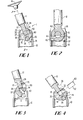
- Member 1-2 is rotatable, along with sockets 24 and 26, relative to member 10 in a second plane perpendicular to the first plane (i. e., in the plane of the drawing). Further, member 12 is rotatable in a third plane about projections 34 and 36 of the sockets, the third plane perpendicular, or orthogonal, to each of the first and second planes.
- the other member 12 is in the form of a cylindrical rod having a flattened end portion 13 and a cylindrical bore 15, or eye, extending between the flattened end faces.
- the bore defines a receptacle 15 opening for receiving projections of the sockets.
- the sockets 24, 26 each have a cylindrical outer surface 32 having a radius of curvature substantially equal to the radius of curvature of the inner wall 30 of the cavity 20.
- the sockets 24, 26 are essentially segments of a cylinder.
- D-shaped projections 34, 36 project from the planar faces 35, 37 of both sockets.
- the curved portion 40 of each D-shaped projection has a radius of curvature substantially equal to the radius of curvature of the bore 15 of the other member 12.
- the height of the projections 34, 36 from the planar faces 35, 37 is preferably less than half the length of the bore 15.
- a D-shaped pin 60 is provided as a locking member for insertion through the socket opening 50 and into the bcre 15.
- the radius of curvature of the D-shaped pin is substantially equal to that of the socket opening 50 and the bore 15 and insertable therewithin.
- the D-shaped pin 60 extends entirely through the bore 15 of the other member 12, abutting the planar face 37 of socket 26.
- sockets 24 and 26 are locked with respect to each other as well as to member 12.
- the pin 60 will tend to prevent relative wobbling or rotation between sockets 24, 26.
- Snap-in action of theD-shaped pin 160 with respect to the socket 124 can also be provided.
- This snap-in action can be provided by a resilient, or retractable member 163 integral, or securable, with the pin 160 that is yieldable or retractable during the insertion of the D-shaped pin 160 within the socket 124, and expandable to engage a recess 125 in the D-shaped socket opening 150.
- Other locking arrangements for retaining the pin within the socket opening should be apparent to one of ordinary skill in the art.
- Such snap-in arrangements can also be used with the embodiment of Figures 1 - 4.
- Figure 7 depicts a socket 226 providing for spring loading of the socket 226 within the cavity 20.
- Spring tabs 228, 229 are formed unitary with the socket 226 and biassed radially outward from the curved surface 232 of the socket, as well as biassed longitudinally along the major cylindrical axis of the socket.
- This spring bias arrangement can take up any lash or wobble that may occur about the major axis of member 10, as well as reducing any noise due to vibration.
- Either or both of the sockets may be formed with such spring tabs.
- rotational lash or noise may be reduced by inserting a separate spring member, such as a belleville washer between one or both of the sockets and the member 12 similar to that shown in the co-pending application.
- Socket 26 is assembled onto the end portion 13 of the other member 12.
- the socket 26 is capable of movement within the bore 15 of the member 12.
- it is necessaty to position the socket 26 in its operative position, i. e., the cylindrical surface 40 of the projection36 is engaging the cylindrical bore 15 of the other member 12.
- the socket 24 is then positioned to sandwich the end portion 13 of the other member.12 between the sockets.
- the socket 24 is at a first position displaced along the major axis of the other member 12.
- the maximum dimension across the pair of sockets and the member 12 is less than, or just equal to, the dimension d of the opening 22 of the cavity 20.
- the socket 24 is shifted in a direction along the major axis of the member 12 into a second position, defined by the mating of the curved portion 40 of the D-shaped projection 34 of the socket 24 with the cylindrical surface of the bore 15.
- the cylindrical surface 32 of the socket 24 engages the inner cylindrical surface 30 of the cavity 20.
- the D-shaped pin 60 is then inserted through the socket opening 50 of the socket 24, which at the second position is in alignment with the bore 15.
- the D-shaped pin 60 extends entirely through the bore 15 such that its end face abuts the planar face 37 of socket 26, thus locking sockets 24 and 26 together.
- pin 60 is removed from the socket opening, the socket 24 is shifted back to its first position such that the maximum transverse dimension of the two sockets and the member 12 are less than or equal to the cavity opening dimension d, and the sockets and member 12 are removed from the housing.
- the D-shaped projection 34 of socket 24 be of a configuration to permit its shiftable longitudinal movement within the bore 15 of the member 12. That is, the D-shaped projection 34 must be less than a semi-circular cross-sectional configuration. The D-shaped projection24 will thus be movable within the bore 15 a distance that is twice the distance between the center line of the bore 15 and the flat face 41 of the D-shaped projection 34.
- Sufficient movement must be provided such that when the member 12 is angled the maximum amount from the major axis of the member 10, the socket 24 can be shifted within the bore 15 a sufficient distance such that the maximum dimension across the pair of sockets and the member 10, in a plane substantially parallel to the housing opening 22, is less than, or just equal to the housing opening dimension d.
Landscapes
- Engineering & Computer Science (AREA)
- General Engineering & Computer Science (AREA)
- Mechanical Engineering (AREA)
- Pivots And Pivotal Connections (AREA)
- Joints Allowing Movement (AREA)
- Quick-Acting Or Multi-Walled Pipe Joints (AREA)
- Steering Controls (AREA)
Applications Claiming Priority (2)
| Application Number | Priority Date | Filing Date | Title |
|---|---|---|---|
| US06/073,974 US4317338A (en) | 1979-09-10 | 1979-09-10 | Universal joint |
| US73974 | 1979-09-10 |
Publications (2)
| Publication Number | Publication Date |
|---|---|
| EP0025403A1 true EP0025403A1 (fr) | 1981-03-18 |
| EP0025403B1 EP0025403B1 (fr) | 1983-07-20 |
Family
ID=22116944
Family Applications (1)
| Application Number | Title | Priority Date | Filing Date |
|---|---|---|---|
| EP80401295A Expired EP0025403B1 (fr) | 1979-09-10 | 1980-09-10 | Joint universel |
Country Status (6)
| Country | Link |
|---|---|
| US (1) | US4317338A (fr) |
| EP (1) | EP0025403B1 (fr) |
| JP (1) | JPS5646191A (fr) |
| CA (1) | CA1145579A (fr) |
| DE (1) | DE3064288D1 (fr) |
| ES (1) | ES260323Y (fr) |
Cited By (1)
| Publication number | Priority date | Publication date | Assignee | Title |
|---|---|---|---|---|
| EP0172959A1 (fr) * | 1984-08-29 | 1986-03-05 | Kawasaki Steel Corporation | Joint universel métallique à blocs coulissants |
Families Citing this family (8)
| Publication number | Priority date | Publication date | Assignee | Title |
|---|---|---|---|---|
| US4540383A (en) * | 1984-03-15 | 1985-09-10 | Allied Corporation | Centering device for a constant velocity joint |
| EP0275632B1 (fr) * | 1986-12-19 | 1991-04-24 | Teleflex Incorporated | Joint universel pour un volant de direction réglable en inclinaison |
| US4941766A (en) * | 1986-12-19 | 1990-07-17 | Teleflex Incorporated | Tilt wheel universal |
| US4834658A (en) * | 1987-07-23 | 1989-05-30 | Koyo Seiko Co., Ltd. | Universal joint |
| EP0446787B1 (fr) * | 1990-03-15 | 1994-11-09 | General Signal Corporation | Appareil d'accouplement de transmission de couple à angle variable |
| AU1107400A (en) | 1998-10-08 | 2000-04-26 | Imo Industries, Inc. | Universal joint for vehicle steering systems |
| DE10236829B4 (de) * | 2002-08-10 | 2004-08-12 | ZF Lemförder Metallwaren AG | Lagerschale für ein Kugelgelenk und Verfahren zu deren Herstellung |
| US20100310305A1 (en) * | 2009-06-09 | 2010-12-09 | Samir Mekid | Spherical joint with internal brake |
Citations (8)
| Publication number | Priority date | Publication date | Assignee | Title |
|---|---|---|---|---|
| DE90864C (fr) * | ||||
| FR427792A (fr) * | 1911-03-16 | 1911-08-12 | Cie Anonyme Francaise Pour La Fabrication Des Roulements A Billes Dwf | Joint universel |
| US1566454A (en) * | 1924-10-09 | 1925-12-22 | Henry W Waits | Universal joint |
| US1837856A (en) * | 1929-12-06 | 1931-12-22 | Fenaille Pierre | Universal coupling |
| US2460648A (en) * | 1944-09-29 | 1949-02-01 | Republic Steel Corp | Universal joint for mill drives |
| DE1189943B (de) * | 1959-02-06 | 1965-04-01 | Kloeckner Werke Ag | Gelenkspindel fuer Walzen |
| US3229481A (en) * | 1963-08-14 | 1966-01-18 | Chrysler Corp | Universal joint |
| US3431751A (en) * | 1967-09-14 | 1969-03-11 | Borg Warner | Anti-backlash universal joint |
Family Cites Families (7)
| Publication number | Priority date | Publication date | Assignee | Title |
|---|---|---|---|---|
| US1368607A (en) * | 1918-02-13 | 1921-02-15 | Cooper Herbert | Universal joint |
| GB284462A (en) * | 1927-01-21 | 1928-02-02 | John Meredith Rubury | Improvements in and relating to universal joints and couplings |
| GB313680A (en) * | 1928-04-02 | 1929-06-20 | John Meredith Rubury | Improvements in and relating to universal joints and couplings |
| GB469711A (en) * | 1936-10-28 | 1937-07-30 | United Eng Foundry Co | Improvements in or relating to universal couplings |
| US2460361A (en) * | 1943-09-22 | 1949-02-01 | Continental Diamond Fibre Co | Slipper bearing |
| US2960341A (en) * | 1956-12-04 | 1960-11-15 | Dorothea A Emrick | Universal link drive for multiple chuck heads |
| US3217515A (en) * | 1963-07-26 | 1965-11-16 | Torrington Co | Preloaded universal joint |
-
1979
- 1979-09-10 US US06/073,974 patent/US4317338A/en not_active Expired - Lifetime
-
1980
- 1980-08-22 CA CA000358946A patent/CA1145579A/fr not_active Expired
- 1980-09-10 EP EP80401295A patent/EP0025403B1/fr not_active Expired
- 1980-09-10 DE DE8080401295T patent/DE3064288D1/de not_active Expired
- 1980-09-10 JP JP12477880A patent/JPS5646191A/ja active Granted
- 1980-09-10 ES ES1980260323U patent/ES260323Y/es not_active Expired
Patent Citations (8)
| Publication number | Priority date | Publication date | Assignee | Title |
|---|---|---|---|---|
| DE90864C (fr) * | ||||
| FR427792A (fr) * | 1911-03-16 | 1911-08-12 | Cie Anonyme Francaise Pour La Fabrication Des Roulements A Billes Dwf | Joint universel |
| US1566454A (en) * | 1924-10-09 | 1925-12-22 | Henry W Waits | Universal joint |
| US1837856A (en) * | 1929-12-06 | 1931-12-22 | Fenaille Pierre | Universal coupling |
| US2460648A (en) * | 1944-09-29 | 1949-02-01 | Republic Steel Corp | Universal joint for mill drives |
| DE1189943B (de) * | 1959-02-06 | 1965-04-01 | Kloeckner Werke Ag | Gelenkspindel fuer Walzen |
| US3229481A (en) * | 1963-08-14 | 1966-01-18 | Chrysler Corp | Universal joint |
| US3431751A (en) * | 1967-09-14 | 1969-03-11 | Borg Warner | Anti-backlash universal joint |
Cited By (1)
| Publication number | Priority date | Publication date | Assignee | Title |
|---|---|---|---|---|
| EP0172959A1 (fr) * | 1984-08-29 | 1986-03-05 | Kawasaki Steel Corporation | Joint universel métallique à blocs coulissants |
Also Published As
| Publication number | Publication date |
|---|---|
| ES260323U (es) | 1982-04-16 |
| JPS5646191A (en) | 1981-04-27 |
| DE3064288D1 (en) | 1983-08-25 |
| US4317338A (en) | 1982-03-02 |
| JPS634045B2 (fr) | 1988-01-27 |
| CA1145579A (fr) | 1983-05-03 |
| ES260323Y (es) | 1982-11-01 |
| EP0025403B1 (fr) | 1983-07-20 |
Similar Documents
| Publication | Publication Date | Title |
|---|---|---|
| EP0025403A1 (fr) | Joint universel | |
| US4139228A (en) | Quarter-turn locking device | |
| US6910737B2 (en) | Seat reclining devices | |
| US4635327A (en) | Quick disconnect locking coupler | |
| KR20080013910A (ko) | 구동 암에 와이퍼 블레이드를 연결시키기 위한 커넥터 | |
| EP0963013B1 (fr) | Connexion de câble monté sur un pare-choc | |
| EP1190921A1 (fr) | Structure de montage de balai d'essuie-glace | |
| EP0022006B1 (fr) | Joint universel | |
| WO1980001670A1 (fr) | Ameliorations aux balais d'essuie-glaces | |
| US4014195A (en) | Pillar lock | |
| CA2183777A1 (fr) | Manette d'embrayage avec pivot pouvant etre raccorde mecaniquement | |
| CN214943280U (zh) | 电驱动锁的安装结构 | |
| CN219762280U (zh) | 一种网圈 | |
| KR100369298B1 (ko) | 차량용 조향축의 유니버셜 조인트 연결구조 | |
| US4249579A (en) | Shaft for a weaving machine | |
| EP0436655B1 (fr) | Moyen de blocage de goupille par came pour un differentiel | |
| KR940005854Y1 (ko) | 커플링 슬리이브 | |
| CN222351227U (zh) | 一种单向传动轴及车载翻转屏设备 | |
| CN223152478U (zh) | 连接件以及显示设备 | |
| CN216580974U (zh) | 折叠机臂以及无人机 | |
| KR970062241A (ko) | 축래치장치 | |
| JPH0352418U (fr) | ||
| CN218037685U (zh) | 驱动力接收件和显影盒 | |
| KR200228834Y1 (ko) | 노브고정장치 | |
| GB1581244A (en) | Adaptors for windscreenwiper blades |
Legal Events
| Date | Code | Title | Description |
|---|---|---|---|
| PUAI | Public reference made under article 153(3) epc to a published international application that has entered the european phase |
Free format text: ORIGINAL CODE: 0009012 |
|
| 17P | Request for examination filed |
Effective date: 19800925 |
|
| AK | Designated contracting states |
Designated state(s): DE FR GB IT |
|
| ITF | It: translation for a ep patent filed | ||
| GRAA | (expected) grant |
Free format text: ORIGINAL CODE: 0009210 |
|
| AK | Designated contracting states |
Designated state(s): DE FR GB IT |
|
| REF | Corresponds to: |
Ref document number: 3064288 Country of ref document: DE Date of ref document: 19830825 |
|
| ET | Fr: translation filed | ||
| PLBE | No opposition filed within time limit |
Free format text: ORIGINAL CODE: 0009261 |
|
| STAA | Information on the status of an ep patent application or granted ep patent |
Free format text: STATUS: NO OPPOSITION FILED WITHIN TIME LIMIT |
|
| PGFP | Annual fee paid to national office [announced via postgrant information from national office to epo] |
Ref country code: DE Payment date: 19840720 Year of fee payment: 5 |
|
| 26N | No opposition filed | ||
| PGFP | Annual fee paid to national office [announced via postgrant information from national office to epo] |
Ref country code: FR Payment date: 19840921 Year of fee payment: 5 |
|
| PG25 | Lapsed in a contracting state [announced via postgrant information from national office to epo] |
Ref country code: FR Free format text: LAPSE BECAUSE OF NON-PAYMENT OF DUE FEES Effective date: 19880531 |
|
| PG25 | Lapsed in a contracting state [announced via postgrant information from national office to epo] |
Ref country code: DE Effective date: 19880601 |
|
| GBPC | Gb: european patent ceased through non-payment of renewal fee | ||
| REG | Reference to a national code |
Ref country code: FR Ref legal event code: ST |
|
| PG25 | Lapsed in a contracting state [announced via postgrant information from national office to epo] |
Ref country code: GB Free format text: LAPSE BECAUSE OF NON-PAYMENT OF DUE FEES Effective date: 19881118 |