EP0025547B1 - Vorrichtung zum Einfalten der Bodenklappen einer Faltschachtel - Google Patents
Vorrichtung zum Einfalten der Bodenklappen einer Faltschachtel Download PDFInfo
- Publication number
- EP0025547B1 EP0025547B1 EP80105219A EP80105219A EP0025547B1 EP 0025547 B1 EP0025547 B1 EP 0025547B1 EP 80105219 A EP80105219 A EP 80105219A EP 80105219 A EP80105219 A EP 80105219A EP 0025547 B1 EP0025547 B1 EP 0025547B1
- Authority
- EP
- European Patent Office
- Prior art keywords
- base
- bottom flaps
- opening
- folding
- platform
- Prior art date
- Legal status (The legal status is an assumption and is not a legal conclusion. Google has not performed a legal analysis and makes no representation as to the accuracy of the status listed.)
- Expired
Links
- 238000000034 method Methods 0.000 description 6
- 238000012856 packing Methods 0.000 description 6
- 238000004806 packaging method and process Methods 0.000 description 5
- 230000006978 adaptation Effects 0.000 description 3
- 230000000284 resting effect Effects 0.000 description 3
- 238000013459 approach Methods 0.000 description 2
- 230000008901 benefit Effects 0.000 description 2
- 239000005022 packaging material Substances 0.000 description 2
- 229920006300 shrink film Polymers 0.000 description 2
- 238000010276 construction Methods 0.000 description 1
- 230000002349 favourable effect Effects 0.000 description 1
- 239000003292 glue Substances 0.000 description 1
- 238000007654 immersion Methods 0.000 description 1
- 238000004519 manufacturing process Methods 0.000 description 1
- 230000036316 preload Effects 0.000 description 1
- 238000003825 pressing Methods 0.000 description 1
Images


Classifications
-
- B—PERFORMING OPERATIONS; TRANSPORTING
- B65—CONVEYING; PACKING; STORING; HANDLING THIN OR FILAMENTARY MATERIAL
- B65B—MACHINES, APPARATUS OR DEVICES FOR, OR METHODS OF, PACKAGING ARTICLES OR MATERIALS; UNPACKING
- B65B7/00—Closing containers or receptacles after filling
- B65B7/16—Closing semi-rigid or rigid containers or receptacles not deformed by, or not taking-up shape of, contents, e.g. boxes or cartons
- B65B7/20—Closing semi-rigid or rigid containers or receptacles not deformed by, or not taking-up shape of, contents, e.g. boxes or cartons by folding-down preformed flaps
Definitions
- the invention relates to a device for folding the bottom flaps of a folding box of the type specified in the preamble of claim 1; such a device is known from US-A-38 46 962.
- the passage opening lies between the front edges of two hinge plates, which are alternately lifted and lowered out of the plane of the support via an eccentric drive in such a way that the front bottom flap of the folding box to be moved toward the passage opening comes to rest on a lowered hinge plate and at the further movement of the other hinge plate, which is simultaneously lifted out of the base, is grasped with its front edge, immersed in the passage opening and brought into the fold-in position.
- a folding roller is connected to a support roller by a pivoting lever and with it about the axes of the rollers of the Roller conveyor parallel pivot axis arranged such that the folding rollers and the support rollers alternately serve as support members for the platform.
- the swiveling axes of the folding tools are additionally arranged to be displaceable relative to one another.
- a further device for folding in arranged behind the first, works in a corresponding manner with the platform, which has meanwhile been rotated through 90 °.
- the object of the present invention is to provide a folding structure which is simpler in comparison and which ensures secure support for the platform with the loaded goods at all times, in particular also in the case of folding boxes with bottom flaps covering the entire folding box bottom.
- bottom flaps are to be closed, which in the closed position leave no space between the edges in front of one another, the two packing table tops must be placed one above the other in close proximity, otherwise the edges of the packing table top that are moving towards each other would collide with each other before reaching the respective closing position of the bottom flap.
- the bottom flaps are connected to the rest of the casing of the folding box in the form of a grooved folding hinge in such a way that when the bottom flap is pivoted away into a lateral position with respect to the rest of the casing, the bottom flap receives a certain internal stress that the bottom flap wants to push back in the direction of its closed position.
- the bottom flap can be closed, for example, by applying glue beforehand or by a clamp-closing device supplied from below through an opening in the base.
- bottom flaps of less depth distance between the folding hinge of the lateral surface and the opposite edge which plunges into the passage opening
- the bottom flaps can automatically fall into the passage opening approaching in the relative guidance in a particularly simple manner be that the depth of the passage opening is chosen approximately equal to the depth of the bottom flaps to be folded.
- the edges delimiting the passage opening are provided in the plane of the base lie and that the pad is mounted on a support frame and can be moved back and forth in its plane until the bottom flaps can be successively grasped by the passage opening and can be folded into their closed position.
- folding boxes of different lengths can be closed in a wide range of variations without a design change to the entire device, if only care is taken to ensure that in the point of reversal of the packing table top which is moved translationally in one direction or the other, the through opening is as far as possible is moved that with subsequent relative movement in the closing direction, the bottom flap can automatically fall into the passage opening.
- Bottom flaps with different widths can be folded in a wide variety of ways using the same device in a particularly simple manner in that the slot length of the slot-shaped opening can be changed in the sense of adaptation to different bottom flap work or bottom flap depths;
- at least one adapter is expediently inserted into the slot-shaped opening or at least one adapter is arranged so that it cannot be lost and locked so that it can be locked.
- a device for folding in the bottom flaps of a folding box with two further opposing bottom flaps with a closing axis that is different from the first or second bottom flap, in particular rotated by 90 ° is characterized according to one embodiment of the invention in that the underlay is assigned to at least one each closing axis Passage opening is designed in the manner of a cross table top.
- a structurally even less complex construction for folding in two bottom flaps in two different closing axes results from the fact that only a single passage opening is provided for two opposing bottom flaps.
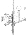
- a folding box 3 with open bottom flaps 31-34, which are open and project laterally to the respective lateral surface 25-38 of the folding box 3, is placed over a platform 4 resting on a base 2.
- a transformer 1 rests on the platform 4 as goods to be packaged, which transformer is firmly connected to the platform 4 by means of an over-stretched plastic skin 5 (shrink film fastening).
- the bottom flaps 31-34 are usually connected in one piece to the respective outer surface 35-38 of the folding box 3 in the form of grooved folding hinges and, upon delivery of the packaging material which has not yet been used, are usually an extension of the outer surface connected in each case via the grooved folding hinge, such that when pivoting away to the side the bottom flaps 31-34 in the position shown in FIG. 1, the bottom flaps 31-34 rest with a certain preload on the base 2.
- the position and opening size of which relative to the bottom flap 31 according to FIG. 1 is chosen such that when the base 2 is guided relative to the stationary platform 4 with the folding box 3 placed over it in the direction A1, the bottom flap 31 is due to its 2, 3 automatically falls into the passage opening 21 and, according to FIGS. 3, 4, is carried along in the further relative guidance of the base in the direction A1 from the rear edge of the passage opening 21 in the closing direction of the bottom flap 31.
- FIGS. 1 to 10 show the device according to the invention automatically. incident bottom flaps. If, when the passage opening 21 approaches the right front edge of the bottom flap 31 (FIG. 1), this edge is briefly “dipped” by machine or manually by an external force, the depth of the slot-shaped opening 21 can be kept very small relative to the depth of the bottom flap 31 .
- a comparable small depth of the slot-shaped opening 21 even when the bottom flaps automatically drop in without an "immersion aid" is possible in that the folding box 3 according to FIGS. 13, 14 advantageously by the bead-like elevation 25 in the relative movement between the base 2 and the Platform 4 is raised in such a way that the bottom flap 31 to be folded in can be fed to the slot-shaped opening 21 in a slightly inclined position (FIGS. 13, 14) to the otherwise flat base 2.
- the bottom flap 31 Due to the slight lifting of the folding box 3, the bottom flap 31 is automatically brought into the inclined position by its internal tension with an inclination directed towards the through opening 21, so that the bottom flap 31 automatically dips into the opening 21 with its right front edge even when the depth is approached and approaches then we took it.
- the sausage-like elevation 25 is due to the low height and can be started up in such a way that it is possible to "drive over" the platform without obstruction.
- the bead-like elevation lies parallel and expediently at such a distance from the passage opening 21 that the apex of the bead-like elevation 25 reaches the folding groove of the bottom flap 21 when its right front edge has reached the passage opening 21.
- Fig. 5 shows the position of the base 2, in which the bottom flap 3 has reached its closed position. It can be seen that the right edge of the folding box 3 is already fully supported by the base 2.
- the base 2 itself rests on a support frame 5, which is provided with an opening 51 for unimpeded folding of the bottom flaps. Through the opening 51 and the passage opening 21, after reaching the closed position according to FIGS. 5 and 10, for example, stapling of the closed bottom flaps 31 and 32 can also be done in a particularly simple manner.
- FIGS. 6 to 10 show the various operating positions of the base 2 relative to the stationary platform 4 with the folding box 3 placed over it and the packaging material contained therein, not shown here, in different operating positions, in order to use the opposite bottom flap 32 after closing the bottom flap 31 to be able to fold in the same base 2 and the single passage opening 21 provided for the closing axis A.
- the support 2 with the single passage opening 21 is first moved in the same direction A1 at least until the second bottom flap 32 also falls into the single passage opening 21.
- the base 2 is now moved back in the opposite direction A2, the second bottom flap 32 also being taken into its closed position according to FIG. 10 in accordance with FIGS. 7-10 in the same manner as previously described for FIGS. 2-5.
- the underlay can advantageously be provided with a number of ball inserts appropriate to the size of the folding box and the weight to be taken up, in order to reduce friction.
- an air cushion guide can be expediently provided between the platform and the base in such a way that the platform is moved contactlessly by an air pressure cushion at a close distance from the base.
- FIG. 11 shows a device according to the invention for folding in the bottom flaps of the bottom flaps of a folding box with two further bottom flaps opposite one another with a closing axis B rotated by 90 ° to that of the first or second bottom flap.
- the closing process for the two opposed bottom flaps 31 and 32 takes place in the embodiment according to FIG. 11 in an equivalent manner to the closing process previously described with reference to FIGS. 1-10, the pad 2 being moved in the closing axis A and the folding box 3 by means of gripping arms 61-64 of a gripping head 6 which are pressed onto the four lateral surfaces 35-38 of the outer surface of the folding box 3 from above.
- bottom flaps 33 and 34 assigned to the closing axis B there is a further single passage opening 22 provided.
- the base 2 is moved in the manner of a cross table top relative to the platform 4 and the folding box 3 into the closing axis B, the bottom flaps 33 and 34 can be taken along and folded in with the passage opening 22 in the same simple manner.
- the passage opening 22 assigned to the closing axis B is introduced into the base 2 crosswise to the passage opening 21 assigned to the closing axis A.
- This crosswise arrangement of the passage openings 21, 22 advantageously requires only short travel distances of the base 2 in the individual folding processes.
- Fig. 11 shows with reference to the passage opening 21, its variability in the sense of an adaptation to different bottom flap widths such that an original passage opening 21, which is comparatively wider than the passage opening 22, by means of adapter pieces 23, 24 to the dimension of the passage opening 22 in FIG. 11 and there foldable bottom flap is reduced.
- the adapter pieces 23, 24 are slidably arranged in the slot-shaped opening 21 and can be locked in their respective adjustment point.
- adapter pieces that can be inserted or clamped in from the outside can also be provided.
- a variable adjustment of the depth of the passage opening can also be provided with regard to bottom flaps of different depths.
- bottom flaps are to be closed, which on the one hand abut one another in the closed position or on the other hand leave a larger space and thus have a much smaller depth.
- FIG. 12 shows a device for folding in with opposite bottom flaps, each assigned to two different shooting axes, in which only one passage opening 21 is provided for the one closing axis A and after the bottom flaps 31, 32 assigned to this closing axis A have been folded in, the base 2 or the folding box 3 with the transformer 1 inserted therein and fastened on the base 2 with the aid of the plastic shrink film 10 relative to the base 2 with the aid of the gripping head 6 and the pressed-on gripping arms 61, 62, the closing axis B of the two other bottom flaps with the movement axis of the base 2 coincides.
- a particularly simple solution for the mechanical drive for the movement of the support 2 relative to the platform 4 is indicated at the same time; for this purpose, the rotary movement of a crank drive 9 is converted into a tangential translatory movement of the base 2 via a crank rod 7 and a pivot lever 8 articulated thereon.
- the lower end 81 of the pivot lever 8 is mounted in a pivot point and, at its upper end 82, which can be pivoted about the pivot point, it engages with a pivot pin 83 in a longitudinal guide groove 23 of a stop bracket 24 fastened to the base 2.
- the folding box 3 is shown in the position which it usually takes in practice after being placed over the goods to be packaged and resting on the platform 4 (transformer 1). Due to the relatively low weight of the folding box 3, on the one hand, and the internal stress of the bottom flaps 31, 32 which are formed on the side surfaces of the folding box via folding grooves and, on the other hand, are initially bent away laterally against their fold-in position, the folding box 3 does not sag until the lower edges of its side surfaces rest on the base 2 through, but is held up by a slight amount by the slightly inclined towards the base 2 and with its outer edges resting on this base bottom flaps, which advantageously benefits a favorable position of the bottom flaps with a small depth of the passage opening.
Landscapes
- Engineering & Computer Science (AREA)
- Mechanical Engineering (AREA)
- Closing Of Containers (AREA)
- Making Paper Articles (AREA)
Priority Applications (1)
| Application Number | Priority Date | Filing Date | Title |
|---|---|---|---|
| AT80105219T ATE5704T1 (de) | 1979-09-15 | 1980-09-02 | Vorrichtung zum einfalten der bodenklappen einer faltschachtel. |
Applications Claiming Priority (2)
| Application Number | Priority Date | Filing Date | Title |
|---|---|---|---|
| DE2937385A DE2937385C2 (de) | 1979-09-15 | 1979-09-15 | Vorrichtung zum Einfalten der Bodenklappen von Faltschachteln |
| DE2937385 | 1979-09-15 |
Publications (2)
| Publication Number | Publication Date |
|---|---|
| EP0025547A1 EP0025547A1 (de) | 1981-03-25 |
| EP0025547B1 true EP0025547B1 (de) | 1983-12-28 |
Family
ID=6080974
Family Applications (1)
| Application Number | Title | Priority Date | Filing Date |
|---|---|---|---|
| EP80105219A Expired EP0025547B1 (de) | 1979-09-15 | 1980-09-02 | Vorrichtung zum Einfalten der Bodenklappen einer Faltschachtel |
Country Status (4)
| Country | Link |
|---|---|
| EP (1) | EP0025547B1 (da) |
| AT (1) | ATE5704T1 (da) |
| DE (2) | DE2937385C2 (da) |
| DK (1) | DK388280A (da) |
Families Citing this family (8)
| Publication number | Priority date | Publication date | Assignee | Title |
|---|---|---|---|---|
| DE3301237A1 (de) * | 1983-01-15 | 1984-08-09 | Focke & Co, 2810 Verden | Verfahren und vorrichtung zum verschliessen von kartons |
| US5259947A (en) * | 1990-12-21 | 1993-11-09 | Conoco Inc. | Solvated mesophase pitches |
| ITBO20040204A1 (it) * | 2004-04-08 | 2004-07-08 | Formetal S R L | Macchina e metodo per piegare falde di chiusura di un imballaggio |
| JP5819804B2 (ja) * | 2012-11-30 | 2015-11-24 | 株式会社フジキカイ | 箱詰機における製函装置 |
| HRP20180186T1 (hr) | 2013-09-18 | 2018-03-23 | Boxem Aps | Postupak gradnje kutije i automatizirana jedinica za gradnju kutije |
| DE102017201842A1 (de) * | 2017-02-06 | 2018-08-09 | Krones Aktiengesellschaft | Handhabungsvorrichtung und Verfahren zum Verschließen von äußeren Bodenlaschen einer Umverpackung |
| CN109353602B (zh) * | 2018-11-30 | 2024-08-30 | 中天智能装备有限公司 | 一种礼品自助机 |
| FR3112330B1 (fr) * | 2020-07-13 | 2022-10-14 | Unista | Machine d’encaissage de produits dans une caisse à rabats de type caisse américaine |
Family Cites Families (4)
| Publication number | Priority date | Publication date | Assignee | Title |
|---|---|---|---|---|
| DE1511722B2 (de) * | 1966-09-28 | 1976-09-09 | Nordischer Maschinenbau Rud. Baader, 2400 Lübeck | Vorrichtung zum einfalten der bodenklappen von faltschachteln |
| US3846962A (en) * | 1971-09-24 | 1974-11-12 | A Rossi | Flap closing mechanism for high speed automatic casing machine |
| US3808770A (en) * | 1972-06-29 | 1974-05-07 | J Berney | Casing machine and method |
| DE2617080A1 (de) * | 1976-04-17 | 1977-10-20 | Nordischer Maschinenbau | Schliesseinrichtung fuer die aeusseren bodenklappen von faltschachteln |
-
1979
- 1979-09-15 DE DE2937385A patent/DE2937385C2/de not_active Expired
-
1980
- 1980-09-02 DE DE8080105219T patent/DE3066006D1/de not_active Expired
- 1980-09-02 AT AT80105219T patent/ATE5704T1/de not_active IP Right Cessation
- 1980-09-02 EP EP80105219A patent/EP0025547B1/de not_active Expired
- 1980-09-12 DK DK388280A patent/DK388280A/da not_active Application Discontinuation
Also Published As
| Publication number | Publication date |
|---|---|
| DE3066006D1 (en) | 1984-02-02 |
| DK388280A (da) | 1981-03-16 |
| EP0025547A1 (de) | 1981-03-25 |
| DE2937385A1 (de) | 1981-03-19 |
| ATE5704T1 (de) | 1984-01-15 |
| DE2937385C2 (de) | 1981-10-01 |
Similar Documents
| Publication | Publication Date | Title |
|---|---|---|
| DE1285449B (de) | Vorrichtung zum Ineinanderlegen von Heften, gefalzten Bogen od. dgl. | |
| DE3220814C2 (de) | Vorrichtung zum Ausrichten eines mit Randlochungen für Bindelemente versehenen Blattstapels | |
| DE2937385C2 (de) | Vorrichtung zum Einfalten der Bodenklappen von Faltschachteln | |
| DE2942883C2 (de) | Vorrichtung zum Verschließen des Bodens einer rechteckigen aufgerichteten Faltschachtel | |
| EP0207059B1 (de) | Verschlussmechanik für Ordner | |
| DE2553612B2 (de) | Verfahren und Vorrichtung zum Eintaschen von Filmabschnitten | |
| DE10043991A1 (de) | Vorrichtung zum Drehen flacher Gegenstände, insbesondere von Faltschachtelzuschnitten | |
| DE559508C (de) | Vorrichtung zum Zufuehren von Faltschachteln zur Fuellstelle | |
| DE1611624A1 (de) | Vorrichtung zum Aufstellen von Schachteln | |
| CH399997A (de) | Vorrichtung für die Herstellung parallelepipedischer Packungen | |
| DE19607084A1 (de) | Umreifungsmaschine, insbesondere Kreuzumreifungsmaschine | |
| DE3705202C1 (en) | Container | |
| DE2938450C2 (de) | Verschließmaschine für Kartons variierender Größe | |
| CH640787A5 (en) | Apparatus for the mechanical wrapping of books in dust jackets | |
| DE2230631C3 (de) | Verfahren zum Herstellen quaderförmiger Schachteln | |
| DE2420584B2 (de) | Wickelmaschine fur Bandmetall o.dgl | |
| DE2902529C2 (da) | ||
| DE2328187C3 (de) | Beilageneinlegevorrichtung an einer Briefumschlagfüllmaschine | |
| DE3330172C2 (de) | Vorrichtung zum paßgenauen Zuschneiden von Glasleisten für Fenster | |
| EP0221356A1 (de) | Einstellbare Faltmaschine | |
| DE1561951C (de) | Vorrichtung zum Verschließen von Faltkartons | |
| DE2443732C3 (de) | Verschlußvorrichtung für einen Fülltrichter | |
| DE2012641C3 (de) | Vorrichtung zum Beleimen und Umfalten der Stirnklappen von gefüllten Kartons | |
| DE1152007B (de) | Vorrichtung zum Herstellen der Boden- und Deckelteile von Stuelpdeckelschachteln | |
| DE3021759A1 (de) | Vorrichtung zum biegen und befestigen der kanten eines behaelters fuer landwirtschaftliche produkte |
Legal Events
| Date | Code | Title | Description |
|---|---|---|---|
| PUAI | Public reference made under article 153(3) epc to a published international application that has entered the european phase |
Free format text: ORIGINAL CODE: 0009012 |
|
| AK | Designated contracting states |
Designated state(s): AT CH DE FR GB IT |
|
| 17P | Request for examination filed |
Effective date: 19810713 |
|
| ITF | It: translation for a ep patent filed | ||
| GRAA | (expected) grant |
Free format text: ORIGINAL CODE: 0009210 |
|
| AK | Designated contracting states |
Designated state(s): AT CH DE FR GB IT LI |
|
| REF | Corresponds to: |
Ref document number: 5704 Country of ref document: AT Date of ref document: 19840115 Kind code of ref document: T |
|
| REF | Corresponds to: |
Ref document number: 3066006 Country of ref document: DE Date of ref document: 19840202 |
|
| ET | Fr: translation filed | ||
| PGFP | Annual fee paid to national office [announced via postgrant information from national office to epo] |
Ref country code: FR Payment date: 19840920 Year of fee payment: 5 |
|
| PLBE | No opposition filed within time limit |
Free format text: ORIGINAL CODE: 0009261 |
|
| STAA | Information on the status of an ep patent application or granted ep patent |
Free format text: STATUS: NO OPPOSITION FILED WITHIN TIME LIMIT |
|
| PGFP | Annual fee paid to national office [announced via postgrant information from national office to epo] |
Ref country code: DE Payment date: 19841128 Year of fee payment: 5 |
|
| PGFP | Annual fee paid to national office [announced via postgrant information from national office to epo] |
Ref country code: CH Payment date: 19841217 Year of fee payment: 5 |
|
| 26N | No opposition filed | ||
| PGFP | Annual fee paid to national office [announced via postgrant information from national office to epo] |
Ref country code: AT Payment date: 19860829 Year of fee payment: 7 |
|
| PG25 | Lapsed in a contracting state [announced via postgrant information from national office to epo] |
Ref country code: GB Effective date: 19890902 Ref country code: AT Effective date: 19890902 |
|
| PG25 | Lapsed in a contracting state [announced via postgrant information from national office to epo] |
Ref country code: LI Effective date: 19890930 Ref country code: CH Effective date: 19890930 |
|
| GBPC | Gb: european patent ceased through non-payment of renewal fee | ||
| PG25 | Lapsed in a contracting state [announced via postgrant information from national office to epo] |
Ref country code: FR Effective date: 19900531 |
|
| REG | Reference to a national code |
Ref country code: CH Ref legal event code: PL |
|
| PG25 | Lapsed in a contracting state [announced via postgrant information from national office to epo] |
Ref country code: DE Effective date: 19900601 |
|
| REG | Reference to a national code |
Ref country code: FR Ref legal event code: ST |