EP0025618A1 - Verfahren zum Erhöhen der Stabilität einer künstlichen Insel mit Hilfe einer Vorausbelastung - Google Patents
Verfahren zum Erhöhen der Stabilität einer künstlichen Insel mit Hilfe einer Vorausbelastung Download PDFInfo
- Publication number
- EP0025618A1 EP0025618A1 EP80200804A EP80200804A EP0025618A1 EP 0025618 A1 EP0025618 A1 EP 0025618A1 EP 80200804 A EP80200804 A EP 80200804A EP 80200804 A EP80200804 A EP 80200804A EP 0025618 A1 EP0025618 A1 EP 0025618A1
- Authority
- EP
- European Patent Office
- Prior art keywords
- legs
- ballast
- bags
- leg
- loading
- Prior art date
- Legal status (The legal status is an assumption and is not a legal conclusion. Google has not performed a legal analysis and makes no representation as to the accuracy of the status listed.)
- Granted
Links
- 238000000034 method Methods 0.000 title claims abstract description 21
- XLYOFNOQVPJJNP-UHFFFAOYSA-N water Substances O XLYOFNOQVPJJNP-UHFFFAOYSA-N 0.000 claims description 15
- 230000008569 process Effects 0.000 claims description 2
- 239000007788 liquid Substances 0.000 abstract description 2
- 239000012530 fluid Substances 0.000 description 8
- 230000008901 benefit Effects 0.000 description 3
- 238000010276 construction Methods 0.000 description 3
- 230000000284 resting effect Effects 0.000 description 3
- 230000009471 action Effects 0.000 description 2
- TZCXTZWJZNENPQ-UHFFFAOYSA-L barium sulfate Chemical compound [Ba+2].[O-]S([O-])(=O)=O TZCXTZWJZNENPQ-UHFFFAOYSA-L 0.000 description 2
- 229910052601 baryte Inorganic materials 0.000 description 2
- 239000010428 baryte Substances 0.000 description 2
- 230000007246 mechanism Effects 0.000 description 2
- 239000000126 substance Substances 0.000 description 2
- 238000006681 Combes synthesis reaction Methods 0.000 description 1
- 238000005553 drilling Methods 0.000 description 1
- 230000002349 favourable effect Effects 0.000 description 1
- 238000003780 insertion Methods 0.000 description 1
- 230000037431 insertion Effects 0.000 description 1
- 238000012986 modification Methods 0.000 description 1
- 230000004048 modification Effects 0.000 description 1
- 239000007787 solid Substances 0.000 description 1
- 238000009966 trimming Methods 0.000 description 1
Images



Classifications
-
- E—FIXED CONSTRUCTIONS
- E02—HYDRAULIC ENGINEERING; FOUNDATIONS; SOIL SHIFTING
- E02B—HYDRAULIC ENGINEERING
- E02B17/00—Artificial islands mounted on piles or like supports, e.g. platforms on raisable legs or offshore constructions; Construction methods therefor
- E02B17/02—Artificial islands mounted on piles or like supports, e.g. platforms on raisable legs or offshore constructions; Construction methods therefor placed by lowering the supporting construction to the bottom, e.g. with subsequent fixing thereto
- E02B17/021—Artificial islands mounted on piles or like supports, e.g. platforms on raisable legs or offshore constructions; Construction methods therefor placed by lowering the supporting construction to the bottom, e.g. with subsequent fixing thereto with relative movement between supporting construction and platform
-
- E—FIXED CONSTRUCTIONS
- E02—HYDRAULIC ENGINEERING; FOUNDATIONS; SOIL SHIFTING
- E02B—HYDRAULIC ENGINEERING
- E02B17/00—Artificial islands mounted on piles or like supports, e.g. platforms on raisable legs or offshore constructions; Construction methods therefor
- E02B2017/0056—Platforms with supporting legs
- E02B2017/006—Platforms with supporting legs with lattice style supporting legs
-
- E—FIXED CONSTRUCTIONS
- E02—HYDRAULIC ENGINEERING; FOUNDATIONS; SOIL SHIFTING
- E02B—HYDRAULIC ENGINEERING
- E02B17/00—Artificial islands mounted on piles or like supports, e.g. platforms on raisable legs or offshore constructions; Construction methods therefor
- E02B2017/0056—Platforms with supporting legs
- E02B2017/0073—Details of sea bottom engaging footing
- E02B2017/0082—Spudcans, skirts or extended feet
Definitions
- This invention relates to a method for increasing the stability of an artificial island by means of pre-loading, said island standing with its legs on the bottom of a body of water and comprising a platform in the form of a pontoon, said pontoon being relatively movable and attachable with respect to said legs, said process of pre-loading being performed by temporarily providing a ballast which can be removed again.
- a method of this kind is generally known.
- the legs In the case of artificial islands which are not resting on a rocky ocean floor but on a combe paratively soft sea bed, the legs have to/provided with such high loads that under all weather and loading conditions the leg will not sink further into the bottom.
- the so-called pre-loading is performed by providing the legs with an additional load.
- the pre-loading is performed by having the weight of the island act on two or three legs, in which the weight is increased with the aid of the mass of the other legs. The consequence is that the jacking and locking mechanism, with which the legs are movable with respect to the pontoon, have to bear the additional heavy load during the pre- loading.
- ballast i.e. water ballast in compartments of the pontoon which are available for this specific purpose and which, therefore, cannot be used otherwise, or by temporarily positioning heavy concrete blocks on deck.
- the jacking- locking mechanisms should resist the full load also in the case of the pre-loading last mentioned, in which case the placing on deck and removal of the blocks will be an additional complication.
- water ballast can be provided by means of a pump and it can be drained off easily.
- the object of this invention to provide a method, with which during the pre-loading the means for locking the legs relatively to the pontoon and for moving said legs do not require additional heavy loading.
- said object is achieved in that the ballast is placed in or on the legs, that said ballast is provided in or on receptables or bearing means releasably attached to or in said legs.
- the invention is based on the principle that the ballast acts no longer on the legs via the locking means but that it acts directly on said legs, e.g. by providing the ballast in the hollow trussed members of the legs.
- the legs consist of tubular members. When these members are filled with ballast, e.g. water, the leg can be provided with an additional weight which is not visible from the outside.
- a plateau can be used which rests on the trussed members of a leg.
- Said plateau may constitute the floor of a reservoir consisting of a number of parts and carry same.
- the bags can be placed in said reservoir or the reservoir as such can be filled with water when the parts are sealingly connected to each other.
- ballasting with receptacles, such as bags, to be mounted in or on the legs can also be carried out in combination with the filling of the hollow trussed members.
- fluid mud is used for the filling of the trussed members, the risk of hardening can be avoided by keeping the fluid mud in circulation, e.g. by the provision of a pump in one of the vertical leg portions.
- a leg construction which can be used when applying the method in accordance with the invention, they hollow trussed members are connected together and a discharge opening, which can be closed, is provided in the proximity of or below the water level when the leg is positioned on the bottom, and a filling hole is provided at a considerable distance from the discharge opening, i.e. above the water level, e.g.
- a fluid mud When the leg is filled with water up to the top and the discharge opening is being opened the water will fall of itself and reach the level of the water outside.
- a fluid mud When a fluid mud is used, it can be expelled by means of a pump or it can flow on the ocean floor via the discharge opening.
- the filling takes place via a separate supply opening or through the open upper end portions of the vertical trussed members.
- Fig. 1 illustrates a pontoon 1 of an artificial island having three legs 2,3 and 4.
- said legs comprise trussed members with closed lower end portions which can be pressed into the bottom 5.
- the pontoon 1 is positioned at a slight distance above sea level 6.
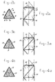
- bags 7-10 are provided in the upper part of each leg between the trussed members. As is shown, each leg has four large bags. It is evident, however, that said bags need not be disposed in the upper part of the legs.
- the space between the horizontal trussed members 11, 12 and 13 of a triangular leg (in horizontal section) is filled with bars 14, 15 and 16 on which, if required with the insertion of a plateau resting on the horizontal trussed members 11-16, three bags 17, 18 and 19 are placed.
- said bags can be placed in the space between the trussed members and filled via opening 20. After having been used, said bags can be emptied again via opening 21.
- the bags are made of e.g. reinforced rubber so that, in filled condition, they are clamped between the trussed members, whereby they may bulge slightly outwards.
- the space is also filled with bags, i.e. only two bags 22 and 23, which butt against each other along plane 24.
- Fig. 4a and 4b illustrate three bags 25, 26 and 27.
- the empty bags are illustrated in the Figures by reference numerals 28, 29, 30, 31 and 32.
- Fig. 5a and 5b two bags 33 and 34 are used. Said bags are lying on top of each other along the lines 35.
- Reference numeral 36 indicates an empty bag.
- the receptacle for taking the ballast comprises a rigid structure formed by wall plates 37, 38 and 39 and bottom plate 40. Said bottom plate rests on the trussed members indicated by reference numeral 41.
- the wall plates and bottom plate can be sealingly connected to each other and they constitute a reservoir which is open at the top, which can be filled at the top and which can be emptied via a discharge opening 42.
- Fig. 7a and 7b show a leg having a square section.
- Beams 45 are disposed on two opposed horizontal trussed members 43, 44 and a plateau is provided on said beams. The beams and the plateau project beyond the trussed members.
- a reservoir consisting of plates 47 sealingly connected to each other is provided inside the trussed members, analogous to Fig. 6a and 6b, and bags 48 and 49 or the like may be placed on the parts of the plateau 46 which project beyond the trussed members.
- this embodiment can also be realized on the other two sides of the framework, in which case the bags are indicated by reference numerals 50 and 51 and a second plateau, analogous to plateau 46, is positioned across plateau 46 and perpendicular thereto.
- Fig. 8 is a diagrammatic side view on a slightly enlarged scale of a leg construction comprising vertical tubular members 52, 53.
- vertical tubular members 52, 53 In the case of a rectangular cross-section, there are four of said tubular members and a triangular cross-section shows three tubular members. Only one side face is illustrated but the other faces of the.leg are identical.
- Horizontal and diagonal tubes 54 and 55 respectively are provided between vertical tubes 52,53. All tubular members are hollow and they are welded together in such a way that they communicate with each other at the joints.
- a construction of this kind can be ballasted with a fluid which is admitted via an open upper end, e.g. at the region of arrow 56, and which can be expelled through a valve 57, shown only diagrammatically.
- ballasting purposes Another advantage of the bags to be used for ballasting purposes is that in empty condition they do not take up much room on board and their weight can be neglected. However, if during the movement of the platform, whereby the pontoon is travelling and the legs are retracted, ballast is needed for the trimming of the platform, it is possible to position one or more filled bags at the proper place in a simple manner.
- An important advantage of the method and device in accordance with the invention is that when the pre-loading of the legs has been performed and the ballast has been taken away the legs regain their profile which is most favourable to withstand wave and wind action.
Landscapes
- Engineering & Computer Science (AREA)
- General Engineering & Computer Science (AREA)
- Mechanical Engineering (AREA)
- Civil Engineering (AREA)
- Structural Engineering (AREA)
- Revetment (AREA)
- Bridges Or Land Bridges (AREA)
Applications Claiming Priority (2)
| Application Number | Priority Date | Filing Date | Title |
|---|---|---|---|
| NL7906710 | 1979-09-07 | ||
| NL7906710A NL7906710A (nl) | 1979-09-07 | 1979-09-07 | Werkwijze en inrichting voor het door voordrukken verhogen van de stabiliteit van een kunstmatig eiland. |
Publications (2)
| Publication Number | Publication Date |
|---|---|
| EP0025618A1 true EP0025618A1 (de) | 1981-03-25 |
| EP0025618B1 EP0025618B1 (de) | 1984-01-25 |
Family
ID=19833806
Family Applications (1)
| Application Number | Title | Priority Date | Filing Date |
|---|---|---|---|
| EP80200804A Expired EP0025618B1 (de) | 1979-09-07 | 1980-08-26 | Verfahren zum Erhöhen der Stabilität einer künstlichen Insel mit Hilfe einer Vorausbelastung |
Country Status (5)
| Country | Link |
|---|---|
| US (1) | US4456402A (de) |
| EP (1) | EP0025618B1 (de) |
| JP (1) | JPS5646018A (de) |
| DE (1) | DE3066286D1 (de) |
| NL (1) | NL7906710A (de) |
Cited By (2)
| Publication number | Priority date | Publication date | Assignee | Title |
|---|---|---|---|---|
| AU602874B2 (en) * | 1985-12-05 | 1990-11-01 | Merck Patent Gesellschaft Mit Beschrankter Haftung | Medicament depot |
| FR2657904A1 (fr) * | 1990-02-08 | 1991-08-09 | Technip Geoproduction | Dispositif de surcharge d'une plate-forme petroliere auto-elevatrice et plate-forme en comportant application. |
Families Citing this family (5)
| Publication number | Priority date | Publication date | Assignee | Title |
|---|---|---|---|---|
| DE60138541D1 (de) * | 2000-05-12 | 2009-06-10 | Deepwater Marine Technology Llc | Temporäre auftriebs- und stabilisationsvorrichtung und verfahren |
| FR2827015B1 (fr) * | 2001-07-06 | 2005-12-23 | Bouygues Offshore | Eolienne offshore et son procede de construction |
| US20180044872A1 (en) * | 2015-03-09 | 2018-02-15 | Noble Drilling Services Inc. | Jackup drilling unit having material storage in jacking legs |
| CN109024283A (zh) * | 2018-07-09 | 2018-12-18 | 贵州新联爆破工程集团有限公司 | 一种支架施工预压加载装置 |
| NL2021708B1 (en) * | 2018-09-25 | 2020-05-07 | Gustomsc Resources Bv | Method for stabilizing a jack-up platform unit |
Citations (2)
| Publication number | Priority date | Publication date | Assignee | Title |
|---|---|---|---|---|
| US3277653A (en) * | 1963-11-26 | 1966-10-11 | Christopher J Foster | Offshore platforms and method of installing same |
| US3453830A (en) * | 1968-03-13 | 1969-07-08 | Mobil Oil Corp | Method and apparatus for alleviating scouring about legs of a marine structure |
Family Cites Families (7)
| Publication number | Priority date | Publication date | Assignee | Title |
|---|---|---|---|---|
| US2318685A (en) * | 1939-11-16 | 1943-05-11 | Gross Henry Emmett | Portable marine foundation |
| US2476309A (en) * | 1944-05-25 | 1949-07-19 | Walter B Lang | Apparatus for subaqueous geologic prospecting |
| US2422168A (en) * | 1945-10-23 | 1947-06-10 | Kirby Dev Corp | Marine tower and method of placing same |
| US2552899A (en) * | 1947-05-19 | 1951-05-15 | Shell Dev | Floating drilling rig |
| US3064437A (en) * | 1955-12-20 | 1962-11-20 | Jersey Prod Res Co | Offshore structure |
| US3097495A (en) * | 1959-05-27 | 1963-07-16 | Alden J Laborde | Platform for afloat-condition drilling |
| US3861158A (en) * | 1973-02-07 | 1975-01-21 | Regal Tool & Rubber | Submerged pipeline stabilization |
-
1979
- 1979-09-07 NL NL7906710A patent/NL7906710A/nl not_active Application Discontinuation
-
1980
- 1980-08-26 EP EP80200804A patent/EP0025618B1/de not_active Expired
- 1980-08-26 DE DE8080200804T patent/DE3066286D1/de not_active Expired
- 1980-09-08 JP JP12449080A patent/JPS5646018A/ja active Pending
- 1980-09-08 US US06/184,978 patent/US4456402A/en not_active Expired - Lifetime
Patent Citations (2)
| Publication number | Priority date | Publication date | Assignee | Title |
|---|---|---|---|---|
| US3277653A (en) * | 1963-11-26 | 1966-10-11 | Christopher J Foster | Offshore platforms and method of installing same |
| US3453830A (en) * | 1968-03-13 | 1969-07-08 | Mobil Oil Corp | Method and apparatus for alleviating scouring about legs of a marine structure |
Non-Patent Citations (2)
| Title |
|---|
| P.T. BOUWKUNDE, vol. 31, no. 5, May 1976, pages 324-325, The Hague, NL. "Een nieuw ontwerp voor een betonnen olieplatform". * |
| PETROLEUM, vol. 30, no. 4, July/August 1967, pages 141-149, London, G.B. F.G. WEST: "The design and construction of offshore drilling outfits". * |
Cited By (4)
| Publication number | Priority date | Publication date | Assignee | Title |
|---|---|---|---|---|
| AU602874B2 (en) * | 1985-12-05 | 1990-11-01 | Merck Patent Gesellschaft Mit Beschrankter Haftung | Medicament depot |
| FR2657904A1 (fr) * | 1990-02-08 | 1991-08-09 | Technip Geoproduction | Dispositif de surcharge d'une plate-forme petroliere auto-elevatrice et plate-forme en comportant application. |
| EP0441673A1 (de) * | 1990-02-08 | 1991-08-14 | Technip Geoproduction | Hubölplattform |
| US5224798A (en) * | 1990-02-08 | 1993-07-06 | Technip Geoproduction | Overloading device for a jack-up oil platform and platform including the device |
Also Published As
| Publication number | Publication date |
|---|---|
| DE3066286D1 (en) | 1984-03-01 |
| NL7906710A (nl) | 1981-03-10 |
| US4456402A (en) | 1984-06-26 |
| JPS5646018A (en) | 1981-04-27 |
| EP0025618B1 (de) | 1984-01-25 |
Similar Documents
| Publication | Publication Date | Title |
|---|---|---|
| US4161376A (en) | Offshore fixed platform and method of erecting the same | |
| US3717001A (en) | Offshore storage structure | |
| DE2106985A1 (de) | Grundanker fur schwimmende Insel | |
| US3824942A (en) | Offshore underwater storage tank | |
| US4456402A (en) | Method for increasing the stability of an artificial island by means of pre-loading | |
| US3553969A (en) | Submerged oil storage structure | |
| CN102762447A (zh) | 通用的再浮起和下水系统及其运行方法 | |
| EP0039590A2 (de) | Offshore-Plattform und Verfahren zur Herstellung, Errichtung und Demontage einer solchen Plattform | |
| US3277653A (en) | Offshore platforms and method of installing same | |
| CA1040440A (en) | Method and apparatus for rapid erection of offshore towers | |
| IE45199B1 (en) | Method of fabrication of off-shore structures and off-shore structures made according to this method | |
| US3306052A (en) | Floatable structure and method of operating same | |
| US3791152A (en) | Offshore storage system | |
| US4127004A (en) | Off-shore platforms and methods for installing the same | |
| US3858402A (en) | Oil storage terminals | |
| JPH0529231Y2 (de) | ||
| OA12146A (en) | Load transfer system. | |
| US4222682A (en) | Platforms for sea-bottom exploitation | |
| EP0333287B1 (de) | Verfahren zum Errichten von wasserbautechnischen Strukturen, wie Molen, Hafendämmen und dergleichen | |
| US2938354A (en) | Structure for offshore operations | |
| US3093972A (en) | Portable marine platform | |
| US5052319A (en) | On-board emergency oil disposal and recovery system | |
| CA1182653A (en) | Underwater structure and method for its construction | |
| USH488H (en) | Hydraulic jacks for controlled load transfer | |
| JPS6047410B2 (ja) | 着地昇降式海上作業台の試験方法 |
Legal Events
| Date | Code | Title | Description |
|---|---|---|---|
| PUAI | Public reference made under article 153(3) epc to a published international application that has entered the european phase |
Free format text: ORIGINAL CODE: 0009012 |
|
| AK | Designated contracting states |
Designated state(s): DE FR GB NL SE |
|
| 17P | Request for examination filed |
Effective date: 19810925 |
|
| RAP1 | Party data changed (applicant data changed or rights of an application transferred) |
Owner name: GUSTO ENGINEERING B.V. |
|
| GRAA | (expected) grant |
Free format text: ORIGINAL CODE: 0009210 |
|
| AK | Designated contracting states |
Designated state(s): DE FR GB NL SE |
|
| REF | Corresponds to: |
Ref document number: 3066286 Country of ref document: DE Date of ref document: 19840301 |
|
| ET | Fr: translation filed | ||
| PGFP | Annual fee paid to national office [announced via postgrant information from national office to epo] |
Ref country code: FR Payment date: 19840824 Year of fee payment: 5 Ref country code: DE Payment date: 19840824 Year of fee payment: 5 |
|
| PGFP | Annual fee paid to national office [announced via postgrant information from national office to epo] |
Ref country code: NL Payment date: 19840831 Year of fee payment: 5 |
|
| PGFP | Annual fee paid to national office [announced via postgrant information from national office to epo] |
Ref country code: SE Payment date: 19840930 Year of fee payment: 5 |
|
| PLBE | No opposition filed within time limit |
Free format text: ORIGINAL CODE: 0009261 |
|
| STAA | Information on the status of an ep patent application or granted ep patent |
Free format text: STATUS: NO OPPOSITION FILED WITHIN TIME LIMIT |
|
| 26N | No opposition filed | ||
| PG25 | Lapsed in a contracting state [announced via postgrant information from national office to epo] |
Ref country code: SE Effective date: 19850827 |
|
| PG25 | Lapsed in a contracting state [announced via postgrant information from national office to epo] |
Ref country code: NL Effective date: 19860301 |
|
| GBPC | Gb: european patent ceased through non-payment of renewal fee | ||
| NLV4 | Nl: lapsed or anulled due to non-payment of the annual fee | ||
| PG25 | Lapsed in a contracting state [announced via postgrant information from national office to epo] |
Ref country code: FR Free format text: LAPSE BECAUSE OF NON-PAYMENT OF DUE FEES Effective date: 19860430 |
|
| PG25 | Lapsed in a contracting state [announced via postgrant information from national office to epo] |
Ref country code: DE Effective date: 19860501 |
|
| REG | Reference to a national code |
Ref country code: FR Ref legal event code: ST |
|
| PG25 | Lapsed in a contracting state [announced via postgrant information from national office to epo] |
Ref country code: GB Effective date: 19881118 |
|
| EUG | Se: european patent has lapsed |
Ref document number: 80200804.5 Effective date: 19860729 |