EP0025650A1 - Apparat und Verfahren zum Bergen einer Bohrausrüstung in einem Bohrloch - Google Patents
Apparat und Verfahren zum Bergen einer Bohrausrüstung in einem Bohrloch Download PDFInfo
- Publication number
- EP0025650A1 EP0025650A1 EP80302905A EP80302905A EP0025650A1 EP 0025650 A1 EP0025650 A1 EP 0025650A1 EP 80302905 A EP80302905 A EP 80302905A EP 80302905 A EP80302905 A EP 80302905A EP 0025650 A1 EP0025650 A1 EP 0025650A1
- Authority
- EP
- European Patent Office
- Prior art keywords
- extractor
- drilling
- equipment
- drilling equipment
- adaption
- Prior art date
- Legal status (The legal status is an assumption and is not a legal conclusion. Google has not performed a legal analysis and makes no representation as to the accuracy of the status listed.)
- Withdrawn
Links
- 238000005553 drilling Methods 0.000 title claims abstract description 68
- 238000000034 method Methods 0.000 title claims description 3
- 238000011084 recovery Methods 0.000 claims abstract description 11
- 238000010168 coupling process Methods 0.000 claims abstract description 10
- 238000005859 coupling reaction Methods 0.000 claims abstract description 10
- 230000008878 coupling Effects 0.000 claims abstract description 3
- 230000000295 complement effect Effects 0.000 claims description 11
- 241000282472 Canis lupus familiaris Species 0.000 claims description 4
- 239000006096 absorbing agent Substances 0.000 description 7
- 230000035939 shock Effects 0.000 description 7
- 239000011435 rock Substances 0.000 description 2
- 238000009825 accumulation Methods 0.000 description 1
- 239000003129 oil well Substances 0.000 description 1
Images

Classifications
-
- E—FIXED CONSTRUCTIONS
- E21—EARTH OR ROCK DRILLING; MINING
- E21B—EARTH OR ROCK DRILLING; OBTAINING OIL, GAS, WATER, SOLUBLE OR MELTABLE MATERIALS OR A SLURRY OF MINERALS FROM WELLS
- E21B31/00—Fishing for or freeing objects in boreholes or wells
- E21B31/12—Grappling tools, e.g. tongs or grabs
- E21B31/20—Grappling tools, e.g. tongs or grabs gripping internally, e.g. fishing spears
Definitions
- the present invention relates to recovery of equipment lost underground during drilling such as rock drilling, water-well drilling and oil well drilling.
- this equipment is referred to as "ground drilling equipment”.
- Ground drilling equipment includes, for a typical 4" (102 mm) diameter bore hole, a "down the hole” drilling hammer with a 4 " (102 mm) diameter bit and a string of 23 ⁇ 4" (70 mm) diameter drilling tubes extending down from a drilling platform to the hammer.
- Individual drilling tubes may be 9 ft. (2750 mm) long and consist of 1 ⁇ 8" (3 mm) wall thickness tubing having male screw-coupling fittings at one end and female fittings at the other end. From time to time the string breaks, generally at a weld between a fitting and the tubing, or less frequently in the middle of the tubing of a tube.
- Extractors exist for recovering the equipment left down the bore hole in the event of a breakage.
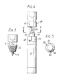
- Conventional extractors consist of a stepped cone having a screw thread on both conical portions as may be seen in Figure 1 which is a side view of a conventional extractor.
- Figure 1 is a side view of a conventional extractor.
- the extractor is hardened, its conical thread often fails to cut a thread in the fitting's cental bore since the fitting is itself hardened to lengthen the life of its own thread. If the fitting is successfully threaded, the new thread is unlikely to extend for more than two threads on account of the taper. This length of thread may well prove insufficient to lift the weight of the lost equipment.
- the larger diameter conical portion 1b of the extractor will engage the tubing. There should be no problem with hardness here, but again only two threads may be cut, the tube being typically only approximately 1 ⁇ 8'' (3 mm) thick for 23 ⁇ 4" (70 mm) tubing.
- the object of the invention is to improve the chances of recovering lost equipment.
- ground drilling equipment having at least one rotatably engageable adaption which is not utilized during normal use of the equipment and which is arranged to co-operate with a complementary rotatably-engageable extractor for recovery of the equipment in the event of loss of the equipment.
- an extractor for recovering ground drilling equipment in accordance with the first aspect of the invention, the extractor having a rotatably engageable adaption complementary to the adaption of the drilling equipment and means including a boss for coupling the extractor to a string of drilling tubes.
- a method of recovering ground drilling equipment consisting in feeding an extractor of the second aspect of the invention to lost drilling equipment of the first aspect, the extractor being coupled to a recovery- string of drilling tubes, engaging the rotatably engageable adaption of the lost drilling equipment with the complementary rotatably-engageable adaption of the extractor and withdrawing the recovery string of drilling tubes, the extractor and the lost drilling equipment.
- the extractor For recovering a string of drilling tubes, the extractor comprises an elongate screw threaded member and a boss from which the threaded member extends.
- the boss is adapted to be connected to a recovery string by means of a female thread.
- the drilling tubes are provided with a female thread in the central bores of the fittings, the thread being complementary to that of the elongate threaded member.
- the thread is preferred that both fittings of a drilling tube are provided with the female thread.
- the male fittings are counter-bored along the axial extent of their male threads, to allow engagement of the extractor in an adjacent female fitting where a male thread has broken off.
- the elongate member is of sufficient length to pass through the full length of one tube. This enables the fitting at the far end of a broken tube to be engaged when the fitting at the near end has broken off.
- the end of the elongate member remote from the boss is preferably pointed to provide self-centring when a fitting is engaged.
- the elongate member has an axial compressed air bore. An indication of whether the extractor has engaged the lost equipment can be gained by passing air through the extractor. If it has engaged the hammer will start operating.
- the spanner flats thereon should be shallower than the presently used flats which are machined to the extent of defining a square which is continuous in cross-section across the fittings, see flats 2 on conventional extractor shown in Figure 1. Further it is proposed that the flats at right angles to each other should be longitudinally spaced. However, conventional square section flats may be used.
- the invention will be employed in respect of drilling tubes in the range of diameters 21 ⁇ 2" (64 mm) to 51 ⁇ 2" (1285 mm) but it may also be employed for a larger range of drilling tubes for example 11 ⁇ 2" (38 mm) to 8" (2040 mm).
- shock absorber Another equipment breakage which can occur is failure of the shock absorber in the hammer.
- the shock absorber connects the hammer to the drilling string with the result that the hammer is lost down the hole if the shock absorber breaks.
- the hammer For recovery of the hammer, it is preferably provided with a pair of bayonet fitting slots and an extractor is provided with a complementary pair of bayonet fitting dogs.
- the bayonet slots are directed in the normal direction of rotation i.e. clockwise, and the trailing edges of the slots are chamfered to keep the slots clear of drilling debris.
- the drilling tube 3 shown in Figure 2 has an upper female screw-coupling fitting 4 and a lower male screw-coupling fitting 5, both fittings being welded to tubing at weld 6 and having spigots 7 that extend into the tubing. It is at either of the welds 6 that the tube is most likely to fail.
- the male fitting 4 has a male screw threaded end 8 adapted to screw into the female screw threaded socket 9 of another tube.
- the fittings are hardened to prolong the life of the threads at 8,9.
- the threads may be of standard Whitworth profile or rope threads for example and may be tapered.
- spanner flats 10 which do not extend across as much of the width of the fittings as they might to obviate the risk of jamming against a loose rock in a bored hole.
- the fittings are provided with screw threaded bores 13, 14 for engagement by the extractor 15 described below with reference to Figure 3.
- the bore 14 in the male fitting 5 is counter-bored at 15' to ensure that should all or part of the male end 8 break away from the fitting 5, the extractor can engage in an adequate length of thread 13 in a female fitting into which the male end 8 is screwed without interference from an out of true thread in the fractured male end. As shown the thread in the female fitting 5 does not extend into the spigot 7.
- the extractor 15 has an elongate threaded member 17 attached to a boss 18 similar to the male fitting 4 whereby the extractor may be fitted to the end of a recovery string of drilling tubes for feeding through a hole to a lost string of other drilling tubes.
- the member 17 may be integral with the boss 18 but is preferably threaded and possibly pinned or otherwise fitted thereto.
- the elongate member is of sufficient length to pass through the tube 3 to engage the thread 14 in the female fitting 5 should the male fitting come away from the tube at its weld 6.
- the extractor For use with 23 ⁇ 4" (70 mm) diameter, 9 ft (2750 mm) long drilling tubes, the extractor is 11 ft (3355 mm) long and its elongate member is 13 ⁇ 8" (35 mm) in diameter.
- the forward end of the elongate member of the extractor is pointed at 19 to guide the tool towards the axis of a broken drilling tube in the event of the extractor reaching the tube eccentrically.
- a bore 20 extends along the length of the elongate member 17 to pass compressed air into the recovered string of drilling tubes.
- An indication of engagement of the elongate member in a thread 13, 14 of the lost equipment is provided by the- compressed air working the lost drilling hammer at the far end of the lost string.
- FIGs 4 and 5 show a drilling hammer 21 which has been lost following fracture of its shock absorber 22 at 23, the shock absorber normally connecting the hammer to its drill string.
- the hammer has a pair of diametrically opposite bayonet-fitting slots 24 which are complementary to a pair of dogs 25 provided on an extractor 26.
- the tool 26 is brought into contact with the hammer and rotated until the dogs 25 engage in the slots 24.
- a counter bore 27 is provided in a boss of the extractor to accommodate the shock absorber.
- the trailing edges 28 of the slots are chamfered to obviate the accumulation of drilling debris in the slots. For the same reason the slots are directed in the direction of normal hammer rotation so that debris does not accumulate at the forward end 29 of the foot of the slots.
Landscapes
- Life Sciences & Earth Sciences (AREA)
- Engineering & Computer Science (AREA)
- Geology (AREA)
- Mining & Mineral Resources (AREA)
- Marine Sciences & Fisheries (AREA)
- Physics & Mathematics (AREA)
- Environmental & Geological Engineering (AREA)
- Fluid Mechanics (AREA)
- General Life Sciences & Earth Sciences (AREA)
- Geochemistry & Mineralogy (AREA)
- Earth Drilling (AREA)
Applications Claiming Priority (2)
| Application Number | Priority Date | Filing Date | Title |
|---|---|---|---|
| GB7930563 | 1979-09-04 | ||
| GB7930563 | 1979-09-04 |
Publications (1)
| Publication Number | Publication Date |
|---|---|
| EP0025650A1 true EP0025650A1 (de) | 1981-03-25 |
Family
ID=10507588
Family Applications (1)
| Application Number | Title | Priority Date | Filing Date |
|---|---|---|---|
| EP80302905A Withdrawn EP0025650A1 (de) | 1979-09-04 | 1980-08-21 | Apparat und Verfahren zum Bergen einer Bohrausrüstung in einem Bohrloch |
Country Status (4)
| Country | Link |
|---|---|
| EP (1) | EP0025650A1 (de) |
| AU (1) | AU549216B2 (de) |
| CA (1) | CA1194858A (de) |
| ZA (1) | ZA805223B (de) |
Families Citing this family (1)
| Publication number | Priority date | Publication date | Assignee | Title |
|---|---|---|---|---|
| CN106759338B (zh) * | 2017-01-23 | 2022-09-30 | 北京健安诚岩土工程有限公司 | 螺纹连接杆件断杆钻取装置及其施工方法 |
Citations (8)
| Publication number | Priority date | Publication date | Assignee | Title |
|---|---|---|---|---|
| US1469493A (en) * | 1921-10-29 | 1923-10-02 | Charles H Brown | Fishing tool |
| US1521482A (en) * | 1924-02-05 | 1924-12-30 | Hampton A Steele | Tool joint |
| US2647008A (en) * | 1950-08-10 | 1953-07-28 | Tri State Oil Tool Company Inc | Retrieving arrangement for well drilling operations |
| US2751019A (en) * | 1954-02-23 | 1956-06-19 | Baker Oil Tools Inc | Apparatus for disengaging threaded joints |
| US2947362A (en) * | 1956-09-06 | 1960-08-02 | Houston Oil Field Mat Co Inc | Fishing tool |
| US3211484A (en) * | 1962-11-02 | 1965-10-12 | Sandvikens Jernverks Ab | Extension rod for drill rods |
| US3667252A (en) * | 1970-11-02 | 1972-06-06 | Nelson Arthur J | Coupling for drill string |
| US3737189A (en) * | 1971-12-23 | 1973-06-05 | Cities Service Oil Co | Reversible tie-back tool |
-
1980
- 1980-08-21 EP EP80302905A patent/EP0025650A1/de not_active Withdrawn
- 1980-08-25 ZA ZA00805223A patent/ZA805223B/xx unknown
- 1980-08-25 CA CA000358939A patent/CA1194858A/en not_active Expired
- 1980-08-28 AU AU61820/80A patent/AU549216B2/en not_active Ceased
Patent Citations (8)
| Publication number | Priority date | Publication date | Assignee | Title |
|---|---|---|---|---|
| US1469493A (en) * | 1921-10-29 | 1923-10-02 | Charles H Brown | Fishing tool |
| US1521482A (en) * | 1924-02-05 | 1924-12-30 | Hampton A Steele | Tool joint |
| US2647008A (en) * | 1950-08-10 | 1953-07-28 | Tri State Oil Tool Company Inc | Retrieving arrangement for well drilling operations |
| US2751019A (en) * | 1954-02-23 | 1956-06-19 | Baker Oil Tools Inc | Apparatus for disengaging threaded joints |
| US2947362A (en) * | 1956-09-06 | 1960-08-02 | Houston Oil Field Mat Co Inc | Fishing tool |
| US3211484A (en) * | 1962-11-02 | 1965-10-12 | Sandvikens Jernverks Ab | Extension rod for drill rods |
| US3667252A (en) * | 1970-11-02 | 1972-06-06 | Nelson Arthur J | Coupling for drill string |
| US3737189A (en) * | 1971-12-23 | 1973-06-05 | Cities Service Oil Co | Reversible tie-back tool |
Also Published As
| Publication number | Publication date |
|---|---|
| AU6182080A (en) | 1981-03-12 |
| AU549216B2 (en) | 1986-01-23 |
| CA1194858A (en) | 1985-10-08 |
| ZA805223B (en) | 1981-08-26 |
Similar Documents
| Publication | Publication Date | Title |
|---|---|---|
| EP0268306A2 (de) | Werkzeugkörper im Bohrloch | |
| EP0678651A2 (de) | Antriebselement zur Verbindung mit einem Bohrmeissel | |
| NO323978B1 (no) | Rørkopling | |
| CA2426020C (en) | Guide tube with threaded ends and waist | |
| NO852118L (no) | Dobbeltkonisk paatrebar borestrengstabilisator. | |
| US6648557B1 (en) | Drilling apparatus and method for single pass bolting | |
| EP1511911B1 (de) | Gewindeverbindung für ein bohrgestänge zum schlaggesteinsbohren | |
| CA1203750A (en) | Oil well packer retriever | |
| AU5052600A (en) | Shank adaptor | |
| GB2057535A (en) | Recovery of ground drilling equipment | |
| CA1058607A (en) | Detachable drill bit for impact drilling | |
| CA1194858A (en) | Recovery of ground drilling equipment | |
| US5722496A (en) | Removable guide member for guiding drill string components in a drill hole | |
| SE460917B (sv) | Borrstraengskomponent foer topphammarborrning | |
| US5234063A (en) | Removable wear protective means for a drilling tool | |
| NO333038B1 (no) | Forbindelse av en forankringsstang med en boreinnretning | |
| US2090822A (en) | Drill collar | |
| US6516904B1 (en) | Mining drill steels and methods of making the same | |
| WO2001092679A1 (en) | Device for raise boring | |
| US2645456A (en) | Wedge-level reamer | |
| EP1532345A1 (de) | SICHERHEITSANORDNUNG F R RûUMER BEIM RAISEBORING | |
| SU1041182A1 (ru) | Метчик дл ликвидации аварий с легкосплавными бурильными трубами | |
| US20240229562A1 (en) | Cutter assembly | |
| US12312866B2 (en) | Drill assembly for percussive drilling, a drill bit and a drill string element | |
| US2124617A (en) | Casing cutter |
Legal Events
| Date | Code | Title | Description |
|---|---|---|---|
| PUAI | Public reference made under article 153(3) epc to a published international application that has entered the european phase |
Free format text: ORIGINAL CODE: 0009012 |
|
| AK | Designated contracting states |
Designated state(s): DE FR IT SE |
|
| 17P | Request for examination filed |
Effective date: 19810830 |
|
| R17P | Request for examination filed (corrected) |
Effective date: 19810820 |
|
| STAA | Information on the status of an ep patent application or granted ep patent |
Free format text: STATUS: THE APPLICATION IS DEEMED TO BE WITHDRAWN |
|
| 18D | Application deemed to be withdrawn |
Effective date: 19830621 |