EP0025655A1 - Commande de température d'un fluide - Google Patents
Commande de température d'un fluide Download PDFInfo
- Publication number
- EP0025655A1 EP0025655A1 EP80302940A EP80302940A EP0025655A1 EP 0025655 A1 EP0025655 A1 EP 0025655A1 EP 80302940 A EP80302940 A EP 80302940A EP 80302940 A EP80302940 A EP 80302940A EP 0025655 A1 EP0025655 A1 EP 0025655A1
- Authority
- EP
- European Patent Office
- Prior art keywords
- fluid
- temperature
- equipment
- heat
- heater
- Prior art date
- Legal status (The legal status is an assumption and is not a legal conclusion. Google has not performed a legal analysis and makes no representation as to the accuracy of the status listed.)
- Withdrawn
Links
Images

Classifications
-
- G—PHYSICS
- G05—CONTROLLING; REGULATING
- G05D—SYSTEMS FOR CONTROLLING OR REGULATING NON-ELECTRIC VARIABLES
- G05D23/00—Control of temperature
- G05D23/19—Control of temperature characterised by the use of electric means
- G05D23/275—Control of temperature characterised by the use of electric means with sensing element expanding, contracting, or fusing in response to changes of temperature
-
- G—PHYSICS
- G01—MEASURING; TESTING
- G01M—TESTING STATIC OR DYNAMIC BALANCE OF MACHINES OR STRUCTURES; TESTING OF STRUCTURES OR APPARATUS, NOT OTHERWISE PROVIDED FOR
- G01M13/00—Testing of machine parts
Definitions
- the invention relates to temperature control of fluids and is especially applicable to controlling the temperature of liquids used in testing or calibrating hydraulic equipment, for example, diesel engine pumps and fuel injectors.
- the calibrating oil is drawn from a large reservoir wherein it is maintained at a fairly constant temperature by an immersion or like heater.
- This arrangement has been found in practice to be unsatisfactory for accurate calibration work since it does not take account of variation of the temperature of the calibrating oil, as applied to the equipment under test, for example because of heating of the oil by use.
- An object of the present invention is to provide means for controlling the temperature of the fluid more accurately.
- apparatus for controlling the temperature of a fluid for calibrating or testing equipment comprises a heat exchanger for connection to the equipment and through which the fluid will pass thereto, means for sensing the temperature of the fluid, and in dependence upon the temperature sensed controlling application of heat to, on removal of heat from, the fluid in the heat exchanger.
- the fluid temperature sensing means which is preferably positioned at the output of the heat exchanger, advantageously may comprise an elongate element disposed in a sleeve so as to provide an annular passage through which the fluid must pass.
- Such an arrangement ensures uniform intimate application of the fluid to the entire length of the temperature sensing element, thus facilitating accurate sensing of the fluid temperature even at high fluid flow rates.
- the temperature sensing means controls, conveniently via switching means, operation of either a heat extractor, or a heater, in dependence upon whether the fluid temperature sensed is higher or lower than a desired temperature.
- the heat extractor may comprise a refrigerant evaporator coil housed in a chamber through which the fluid will pass in use.
- evaporator coil may be coupled to a conventional refrigerator unit, conveniently of the compression type having a compressor, condenser and a capillary metering device to meter liquid refrigerant into the evaporator coil.
- By-pass mean3 may be provided for coupling the output of the condenser of such refrigeration unit directly to the evaporator coil, so that hot liquid or gas, i.e. the compressed refrigerant, from the condenser is injected directly into the evaporator coil.
- the by-pass means may be controlled by a fluid regulator valve, conveniently solenoid operated in conjunction with the heating means.
- the evaporator coil and its housing are cylindrical, and means for heating the fluid comprises an elongate electrical immersion heater element extending generally coaxially within the evaporator coil from one end of the housing.
- the switching means operated by the temperature sensor may be arranged to switch directly from one mode to the other according to whether the temperature sensed is above or below a predetermined level, perhaps with hysteresis providing a small range, say + 2 0 C between highest and lowest switching temperatures.
- the arrangement may be such that one or more switches and/or elements are operated on transition of respective different temperature settings.
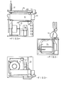
- apparatus for controlling the temperature of oil for use in calibrating diesel engine pumps, fuel injectors or the like comprises a heat exchanger 10 formed by a copper cylinder 11 having an inlet 12 at one end and an outlet 13 at the opposite end.
- a connector 14 couples the outlet 13 to a tube 15 which extends parallel to the cylinder 11 and in which is located the sensing element 16 of a thermostat 17.
- the element is of lesser diameter than the interior of the tube so providing an annular space 18 therebetween which is sealed at that end from which the element protrudes.
- the thermostat is of conventional form and has an electric switch 35 housed in a casing 19. The temperature at which the switch operates can be set by means of a control knob 20.
- the heat exchanger cylinder 11 houses a close coiled helical coil 23 of " diameter copper tube.
- the coil 23 is of only slightly lesser external diameter than the interior of the cylinder and constitutes the evaporator of a refrigeration unit.
- the remaining parts of the refrigeration unit are of conventional construction and comprise a motor compressor 24, condenser 25 and condenser fan 26.
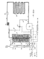
- a capillary-type metering device 27 meters the liquid refrigerant from the condenser 25 into the evaporator coil 23 (see Figures 3 and 5).
- a drier 37 may be provided between the condenser 25 and the evaporator coil 23.
- One end of the cylinder 11 is closed by a brass end plate 28 and the other end by an annular brass plate 29 internally screwthreaded to receive an immersion heater 30 such that its three heating elements 32 (two only are shown) extend axially into the cylinder 11 within the evaporator coil 10.
- the heater of 1kw capacity, is specially suited for heating oil and viscous substances.
- the immersion heater element is connected to one contact of the changeover switch 35a of the thermostat, the other contact 35b being connected to the refrigeration unit compressor motor 24.
- the changeover contact 35c is connected to a switched power supply means 36.
- calibrating oil from a reservoir enters the inlet pipe 12, as indicated by arrow A, passes axially along the cylinder 11, through the outlet 14 and into the annular space 16 between the thermostat element and the tube 15. The oil leaves the tube 15 as indicated by arrow B and thence passes to the equipment under test.
- thermostat If the oil temperature is too high the thermostat operates switch 35 to connect the electrical supply 36 via switch contact 35b to the compressor 24 of the refrigeration unit to cool the oil as it passes through and around the evaporator coil 23. On the other hand if the oil is too cool, the thermostat switches the electrical supply 36 via switch contact 35a to the immersion heater.
- the thermostat is designed so that, when the temperature is within a predetermined range, typically 2 0 C, neither the refrigeration unit nor the heater are energised.
- thermostat 34 is provided, as a safety device, ( conveniently extending within the immersion heater coils as shown in Figure 4) to disconnect the electrical supply 36 from the heater at a given temperature.
- a safety device conveniently extending within the immersion heater coils as shown in Figure 4 to disconnect the electrical supply 36 from the heater at a given temperature.
- a refrigeration unit facilitates fast reaction to overheating of the oil, say in the equipment under test, by providing positive cooling of the oil rather than merely allowing the oil to cool by discontinuing heating.
- thermostat element in an outlet tube ensuring that the fluid must flow over substantially the entire length of the element, and also that the temperature of the fluid is sensed immediately before it leaves the apparatus.
- the heat exchanger slopes upwards at about 5° towards the outlet end. It has been found that this arrangement is especially advantageous because it reduces the incidence of air bubbles or voids forming in the fluid which would reduce effective heat exchange. Nevertheless a certain amount of turbulent flow is desirable to ensure uniform heating/cooling and this is assisted by the spacing between individual turns of the evaporator coil 23.
- the immersion heater might be dispensed with and the refrigeration unit adapted to operate as a reversible heat pump i.e. the evaporator coil being used as the heater.
- the refrigeration unit adapted to operate as a reversible heat pump i.e. the evaporator coil being used as the heater.
- such an arrangement would probably be more complex and less quick to react to temperature variation as the previously described embodiment so would probably be used for controlling fluid temperatures in fields other than equipment calibration etc. where accuracy is not paramount
- FIG. 5 One possible modification is illustrated in broken lines in Figure 5 and comprises a by-pass line 40, 41 which connects the output of the compressor 24 by way of a solenoid operated valve 42, directly to the input of the evaporator coil 23, in effect by-passing the condenser 25, drier 37 and capillary device 27.
- the operating coil of the solenoid valve 42 is connected via one pole of a double pole switch 38, in parallel with the immersion heater 30.
- the other pole of switch 38 connects the compressor 24 directly to the supply 36. Closure of switch 38 renders the by-pass system operative.
- valve 42 In operation, when the thermostat switches the electrical supply to the immersion heater 30, valve 42 is opened and condenser 25 acts as a heat pump, injecting hot refrigerant li q uid/gas directly into the evaporator coil 23. This is of considerable benefit at the commencement of a test sequence and experiments have shown that warm-up time can be reduced by approximately 50%.
- compressor 24 may be connected directly to the supply 36, whether the by-pass is fitted or not.
Landscapes
- Physics & Mathematics (AREA)
- General Physics & Mathematics (AREA)
- Engineering & Computer Science (AREA)
- Automation & Control Theory (AREA)
- Testing Resistance To Weather, Investigating Materials By Mechanical Methods (AREA)
- Testing Of Engines (AREA)
Applications Claiming Priority (2)
| Application Number | Priority Date | Filing Date | Title |
|---|---|---|---|
| GB7929866 | 1979-08-29 | ||
| GB7929866 | 1979-08-29 |
Publications (1)
| Publication Number | Publication Date |
|---|---|
| EP0025655A1 true EP0025655A1 (fr) | 1981-03-25 |
Family
ID=10507469
Family Applications (1)
| Application Number | Title | Priority Date | Filing Date |
|---|---|---|---|
| EP80302940A Withdrawn EP0025655A1 (fr) | 1979-08-29 | 1980-08-26 | Commande de température d'un fluide |
Country Status (6)
| Country | Link |
|---|---|
| EP (1) | EP0025655A1 (fr) |
| AU (1) | AU6190480A (fr) |
| BR (1) | BR8005462A (fr) |
| CA (1) | CA1137779A (fr) |
| GB (1) | GB2062830B (fr) |
| ZA (1) | ZA805298B (fr) |
Cited By (2)
| Publication number | Priority date | Publication date | Assignee | Title |
|---|---|---|---|---|
| CN103440001A (zh) * | 2013-08-30 | 2013-12-11 | 上海索达传动机械有限公司 | 一种润滑油油温控制系统 |
| CN117780744A (zh) * | 2024-02-27 | 2024-03-29 | 智奇铁路设备有限公司 | 一种液压油循环冷却装置 |
Citations (8)
| Publication number | Priority date | Publication date | Assignee | Title |
|---|---|---|---|---|
| US2645461A (en) * | 1948-08-26 | 1953-07-14 | Socony Vacuum Oil Co Inc | Thermoregulator |
| US3318372A (en) * | 1965-06-21 | 1967-05-09 | Earl R Shell | Emergency control system for a heat pump and method |
| DE1404918A1 (de) * | 1961-05-02 | 1969-04-10 | Alfred Eckerfeld | Durchlauferhitzer mit thermisch gesteuerter Durchlaufmenge |
| US3465564A (en) * | 1967-05-04 | 1969-09-09 | Nassau Smelting & Refining Co | Method and control system for measuring and regulating the rolling temperature of a rolling mill |
| US3557565A (en) * | 1969-03-24 | 1971-01-26 | American Air Filter Co | Thermal device calibrating apparatus |
| US3680630A (en) * | 1969-10-09 | 1972-08-01 | Tronac Inc | Temperature control system with heater-cooler |
| US3779457A (en) * | 1971-06-28 | 1973-12-18 | Trw Inc | Data normalizing method and system |
| US3809856A (en) * | 1972-10-20 | 1974-05-07 | Wynn R | Water heater |
-
1980
- 1980-08-26 EP EP80302940A patent/EP0025655A1/fr not_active Withdrawn
- 1980-08-26 GB GB8027608A patent/GB2062830B/en not_active Expired
- 1980-08-27 ZA ZA00805298A patent/ZA805298B/xx unknown
- 1980-08-28 BR BR8005462A patent/BR8005462A/pt unknown
- 1980-08-28 CA CA000359219A patent/CA1137779A/fr not_active Expired
- 1980-08-29 AU AU61904/80A patent/AU6190480A/en not_active Abandoned
Patent Citations (8)
| Publication number | Priority date | Publication date | Assignee | Title |
|---|---|---|---|---|
| US2645461A (en) * | 1948-08-26 | 1953-07-14 | Socony Vacuum Oil Co Inc | Thermoregulator |
| DE1404918A1 (de) * | 1961-05-02 | 1969-04-10 | Alfred Eckerfeld | Durchlauferhitzer mit thermisch gesteuerter Durchlaufmenge |
| US3318372A (en) * | 1965-06-21 | 1967-05-09 | Earl R Shell | Emergency control system for a heat pump and method |
| US3465564A (en) * | 1967-05-04 | 1969-09-09 | Nassau Smelting & Refining Co | Method and control system for measuring and regulating the rolling temperature of a rolling mill |
| US3557565A (en) * | 1969-03-24 | 1971-01-26 | American Air Filter Co | Thermal device calibrating apparatus |
| US3680630A (en) * | 1969-10-09 | 1972-08-01 | Tronac Inc | Temperature control system with heater-cooler |
| US3779457A (en) * | 1971-06-28 | 1973-12-18 | Trw Inc | Data normalizing method and system |
| US3809856A (en) * | 1972-10-20 | 1974-05-07 | Wynn R | Water heater |
Cited By (4)
| Publication number | Priority date | Publication date | Assignee | Title |
|---|---|---|---|---|
| CN103440001A (zh) * | 2013-08-30 | 2013-12-11 | 上海索达传动机械有限公司 | 一种润滑油油温控制系统 |
| CN103440001B (zh) * | 2013-08-30 | 2016-03-09 | 上海索达传动机械有限公司 | 一种润滑油油温控制系统 |
| CN117780744A (zh) * | 2024-02-27 | 2024-03-29 | 智奇铁路设备有限公司 | 一种液压油循环冷却装置 |
| CN117780744B (zh) * | 2024-02-27 | 2024-05-10 | 智奇铁路设备有限公司 | 一种液压油循环冷却装置 |
Also Published As
| Publication number | Publication date |
|---|---|
| ZA805298B (en) | 1981-06-24 |
| BR8005462A (pt) | 1981-03-10 |
| GB2062830A (en) | 1981-05-28 |
| CA1137779A (fr) | 1982-12-21 |
| GB2062830B (en) | 1984-07-25 |
| AU6190480A (en) | 1981-03-05 |
Similar Documents
| Publication | Publication Date | Title |
|---|---|---|
| DE1751826C2 (de) | Kühleinrichtung | |
| US20100086289A1 (en) | Modular tankless water heater with precise power control circuitry and structure | |
| US6509553B2 (en) | Method and apparatus for providing an indication of the composition of a fluid particularly useful in heat pumps and vaporizers | |
| EP0759168B1 (fr) | Dispositif d'analyse de fluides | |
| US4612106A (en) | Cooling system for a slab gel electrophoresis apparatus | |
| US3570310A (en) | Flow-indicating device | |
| US6324857B1 (en) | Laboratory thermostat | |
| EP0025655A1 (fr) | Commande de température d'un fluide | |
| JPH0678963B2 (ja) | 冷媒システム用冷媒漏洩検出補助方法及び装置 | |
| KR20050075803A (ko) | 냉동사이클 성능검사장치 | |
| GB2299005A (en) | Vaporising liquids | |
| US3502026A (en) | Electromagnetic pump | |
| RU2220381C1 (ru) | Устройство для нагрева проточной жидкости | |
| EP0558860A1 (fr) | Vanne de commande d'appareil de chauffage et dispositif de chauffage comportant une telle vanne | |
| EP0057596A2 (fr) | Appareil pour déterminer la température de liquéfaction ou d'ébullition d'un échantillon | |
| JPS62142932A (ja) | 暖房装置 | |
| CA1199817A (fr) | Methode et dispositif d'epreuve des clapets thermostatiques d'un systeme de refroidissement a l'eau pour moteur de locomotive | |
| EP2183567B1 (fr) | Analyseur reid de la tension de vapeur doté d'un tampon de saturation d'air | |
| JP2588337B2 (ja) | 液体冷却剤及び多種の冷却剤を操作可能な冷却剤操作システム | |
| CN210136427U (zh) | 绕组温控器校验装置及其恒温槽系统 | |
| US3230769A (en) | Pneumatic gauge system | |
| US1948731A (en) | Water heater | |
| EP0221210A1 (fr) | Appareil de chauffage | |
| US4019530A (en) | Chemical diluting system | |
| CN219263911U (zh) | 一种轴承试验器高精度高温润滑装置 |
Legal Events
| Date | Code | Title | Description |
|---|---|---|---|
| PUAI | Public reference made under article 153(3) epc to a published international application that has entered the european phase |
Free format text: ORIGINAL CODE: 0009012 |
|
| AK | Designated contracting states |
Designated state(s): AT BE CH DE FR IT LU NL SE |
|
| 17P | Request for examination filed |
Effective date: 19810825 |
|
| STAA | Information on the status of an ep patent application or granted ep patent |
Free format text: STATUS: THE APPLICATION IS DEEMED TO BE WITHDRAWN |
|
| 18D | Application deemed to be withdrawn |
Effective date: 19830516 |