EP0025806A1 - Dispositif de nettoyage du blanchet - Google Patents
Dispositif de nettoyage du blanchet Download PDFInfo
- Publication number
- EP0025806A1 EP0025806A1 EP79103639A EP79103639A EP0025806A1 EP 0025806 A1 EP0025806 A1 EP 0025806A1 EP 79103639 A EP79103639 A EP 79103639A EP 79103639 A EP79103639 A EP 79103639A EP 0025806 A1 EP0025806 A1 EP 0025806A1
- Authority
- EP
- European Patent Office
- Prior art keywords
- washing
- washing liquid
- nozzle bar
- liquid
- pump
- Prior art date
- Legal status (The legal status is an assumption and is not a legal conclusion. Google has not performed a legal analysis and makes no representation as to the accuracy of the status listed.)
- Granted
Links
- 238000004140 cleaning Methods 0.000 title description 2
- 238000005406 washing Methods 0.000 claims abstract description 46
- 239000007788 liquid Substances 0.000 claims abstract description 44
- 239000004744 fabric Substances 0.000 claims abstract description 9
- 238000007664 blowing Methods 0.000 claims abstract description 3
- 239000012530 fluid Substances 0.000 claims description 2
- 239000007921 spray Substances 0.000 description 9
- 238000000034 method Methods 0.000 description 3
- 239000000654 additive Substances 0.000 description 2
- 230000000996 additive effect Effects 0.000 description 2
- 239000003599 detergent Substances 0.000 description 2
- 238000001035 drying Methods 0.000 description 2
- 238000009420 retrofitting Methods 0.000 description 2
- XLYOFNOQVPJJNP-UHFFFAOYSA-N water Substances O XLYOFNOQVPJJNP-UHFFFAOYSA-N 0.000 description 2
- 230000006978 adaptation Effects 0.000 description 1
- 238000000889 atomisation Methods 0.000 description 1
- 238000011109 contamination Methods 0.000 description 1
- 238000010586 diagram Methods 0.000 description 1
- 238000009826 distribution Methods 0.000 description 1
- 238000005429 filling process Methods 0.000 description 1
- 238000002156 mixing Methods 0.000 description 1
- 238000007645 offset printing Methods 0.000 description 1
- 238000007639 printing Methods 0.000 description 1
- 238000005507 spraying Methods 0.000 description 1
- 238000003860 storage Methods 0.000 description 1
Images

Classifications
-
- B—PERFORMING OPERATIONS; TRANSPORTING
- B41—PRINTING; LINING MACHINES; TYPEWRITERS; STAMPS
- B41F—PRINTING MACHINES OR PRESSES
- B41F35/00—Cleaning arrangements or devices
- B41F35/06—Cleaning arrangements or devices for offset cylinders
-
- B—PERFORMING OPERATIONS; TRANSPORTING
- B05—SPRAYING OR ATOMISING IN GENERAL; APPLYING FLUENT MATERIALS TO SURFACES, IN GENERAL
- B05B—SPRAYING APPARATUS; ATOMISING APPARATUS; NOZZLES
- B05B15/00—Details of spraying plant or spraying apparatus not otherwise provided for; Accessories
- B05B15/50—Arrangements for cleaning; Arrangements for preventing deposits, drying-out or blockage; Arrangements for detecting improper discharge caused by the presence of foreign matter
- B05B15/55—Arrangements for cleaning; Arrangements for preventing deposits, drying-out or blockage; Arrangements for detecting improper discharge caused by the presence of foreign matter using cleaning fluids
-
- B—PERFORMING OPERATIONS; TRANSPORTING
- B41—PRINTING; LINING MACHINES; TYPEWRITERS; STAMPS
- B41P—INDEXING SCHEME RELATING TO PRINTING, LINING MACHINES, TYPEWRITERS, AND TO STAMPS
- B41P2235/00—Cleaning
- B41P2235/10—Cleaning characterised by the methods or devices
- B41P2235/20—Wiping devices
- B41P2235/23—Brushes
Definitions
- the invention relates to a rubber blanket washing device with a wash cloth that can be placed on the rubber blanket and can be conveyed step by step, and which can be moistened by means of a nozzle bar which can be supplied with washing liquid by at least one pump.
- the nozzle bar is supplied with washing liquid by a high-pressure pump in such a way that it is always present at the spray nozzles and flows out through the pump during operation.
- a high-pressure pump in such a way that it is always present at the spray nozzles and flows out through the pump during operation.
- an exact dosage of the amount of liquid dispensed by the spray nozzles is practically impossible to achieve in arrangements of this type.
- This object is achieved in a surprisingly simple manner according to the invention in that a precisely predeterminable dose of washing liquid can be introduced into the nozzle bar at least once during each work cycle and that the nozzle bar can be connected to a compressed air source for blowing out the received washing liquid dose after such an exposure .
- a washing liquid composed of several, sometimes very aggressive, components.
- this can be achieved in a simple manner in that a pump is provided for each component, which is preferably connected via a liquid line secured by a non-return valve to a common supply nozzle of the nozzle bar, to which is simultaneously secured by a non-return valve compressed air line ISTL connected within the sometimes very lam g s liquid line while no mixing takes place in an advantageous manner.
- washing liquid pump or pumps is designed as a piston pump with an adjustable stroke. This enables a precisely defined funding volume to be achieved with an adaptation to the Beddrf that is still guaranteed
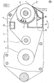
- the rubber cylinder of an offset printing machine is indicated at 1, of a type known per se, to which a washing device, designated as a whole by 2, is assigned.
- This has a frame which is delimited by lateral end shields 3 and is pivotably suspended in the printing press frame.
- the washing device 2 works with a washing cloth 4, which can be gradually wound up from a storage drum 5 and onto a take-up drum 6.
- the washing cloth 4 is guided via a blanket cylinder 1 opposite, here made as a brush roller platen roller 7, the can be adjusted to the rubber cylinder 1 by pivoting the frame delimited by the end shields 3.
- the brush roller 7 abuts a trough-shaped support plate 9 approximately diametrically opposite the contact zone 8.
- a nozzle bar 11 with spray nozzles 10 is provided, which is expediently arranged within the space delimited by the washing cloth 4 and is thus practically encapsulated by the washing cloth 4 itself, which provides excellent protection of the neighboring machine parts against moistening by the Spray nozzles 10 offers. At the same time, this ensures that the washcloth 4 can simply be inserted in the form of an envelope when changing the washcloth.
- guide cross members 12 and 13 are provided here, which can be connected to the side bearing plates 2 to form a stable frame.
- the guide crossbeam 12 also serves as a receptacle for the nozzle baffle 11 and as a receptacle for washing liquid which may drip off.
- the nozzle bar 11 is provided with a supply connection 14 which, as in the exemplary embodiment shown, can be branched over its entire width to ensure uniform application of the nozzle bar.
- a compressed air line 15 connected to a compressed air source and at least one, in the exemplary embodiment shown, two liquid lines which can be acted upon by an associated pump 16 each open into the supply connection 14 17 a.
- Each strand 17 is assigned to a specific washing liquid component. For example, the strand of water shown on the right in FIG. 2 and the strand shown on the left should carry an additive for detergent.
- the pumps 16 are expediently designed as piston pumps in order to achieve precise meterability of the washing liquid supplied to the nozzle bar 11.
- these are so-called suction and pressure pumps, each of which is connected to the assigned water tank 19 or the assigned detergent additive tank 20 with a suitable suction line 18.
- the check valves of the pumps are indicated at 21.
- the compressed air line 15 is here simply connected to a compressed air network indicated by the ring line 22. In the area of their connection to the supply nozzle 14, the compressed air line 15 and the liquid lines 17 are each secured by a check valve 23, so that any contamination is avoided.
- the supply nozzle 14 and the nozzle bar 11 provided therewith have a certain capacity for washing liquid, for example in the form of the collecting space 24 indicated here in dashed lines, to which all the spray nozzles are connected.
- a predetermined amount of liquid is now introduced into the nozzle bar 11 as a function of the gradual further transport of the washcloth 4 by corresponding actuation of the pumps 16.
- the pumps 16 are each to perform one stroke for this purpose.
- the stroke size of the pumps 16 is expediently adjustable, which is a precise adjustment of the pump stroke to the respective fluid requirements. So that no liquid can escape through the spray nozzles 10 when the nozzle bar 11 is acted upon, the maximum joint stroke volume of all pumps 16 should be less than the capacity of the nozzle bar 11 and of the supply nozzle 14 reaching as far as the check valves.
- the compressed air line 15 is now activated and the reservoir formed by the capacity of the nozzle bar and the supply connection connected therewith is emptied by the inflowing compressed air.
- a valve 25 is provided in the compressed air line 15, which is controlled by means of a control device (not shown here) in such a way that the compressed air line 15 is activated as soon as the pumps 16 have ended their stroke.
- the pumps 16 are pneumatically actuated, control slides 27 being provided in the drive line 26 leading to the ring line 22, which are controlled via the control device (not shown here) in such a way that the pumps 16 and thus the liquid strands 17 run counter to the compressed air line 15 activated or passivated.
- One spray cycle of the type described above is normally sufficient per wash cloth step. If more washing liquid is required, two or more spray cycles can also be provided per step.
- the nozzle bar 11 can only be pressurized with compressed air.
- the pumps 16 are simply shut down and the valve 25 is held in the open position by a suitable control pulse.
Landscapes
- Inking, Control Or Cleaning Of Printing Machines (AREA)
- Treatment Of Fiber Materials (AREA)
Priority Applications (1)
| Application Number | Priority Date | Filing Date | Title |
|---|---|---|---|
| EP79103639A EP0025806B1 (fr) | 1979-09-25 | 1979-09-25 | Dispositif de nettoyage du blanchet |
Applications Claiming Priority (1)
| Application Number | Priority Date | Filing Date | Title |
|---|---|---|---|
| EP79103639A EP0025806B1 (fr) | 1979-09-25 | 1979-09-25 | Dispositif de nettoyage du blanchet |
Publications (2)
| Publication Number | Publication Date |
|---|---|
| EP0025806A1 true EP0025806A1 (fr) | 1981-04-01 |
| EP0025806B1 EP0025806B1 (fr) | 1983-05-25 |
Family
ID=8186200
Family Applications (1)
| Application Number | Title | Priority Date | Filing Date |
|---|---|---|---|
| EP79103639A Expired EP0025806B1 (fr) | 1979-09-25 | 1979-09-25 | Dispositif de nettoyage du blanchet |
Country Status (1)
| Country | Link |
|---|---|
| EP (1) | EP0025806B1 (fr) |
Cited By (5)
| Publication number | Priority date | Publication date | Assignee | Title |
|---|---|---|---|---|
| AU614794B2 (en) * | 1988-09-13 | 1991-09-12 | Nikka Kabushiki Kaisha | Cleaning apparatus and method of cleaning a blanket cylinder of a printing press |
| WO1995007182A1 (fr) * | 1993-09-08 | 1995-03-16 | Jimek International Ab | Tube de pulverisation pour dispositif de lavage de blanchet d'une presse d'impression |
| EP0572391B1 (fr) * | 1990-03-06 | 1995-10-18 | BERNTSSON, Reinhold | Systeme situe au niveau d'une mouilleuse a pulverisation |
| DE10030027A1 (de) * | 2000-06-17 | 2001-12-20 | Baldwin Grafotec Gmbh | Waschvorrichtung für Druckmaschinenzylinder |
| EP1642717A1 (fr) * | 2004-10-01 | 2006-04-05 | Technotrans AG | Dispositif de nettoyage de surfaces de cylindres dans une machine d'impression |
Families Citing this family (4)
| Publication number | Priority date | Publication date | Assignee | Title |
|---|---|---|---|---|
| DE102004011861A1 (de) * | 2004-03-11 | 2005-09-29 | Koenig & Bauer Ag | Reinigungsvorrichtung |
| DE102004011859A1 (de) * | 2004-03-11 | 2005-09-29 | Koenig & Bauer Ag | Reinigungsvorrichtung für einen Zylinder oder eine Walze |
| DE102004011860A1 (de) * | 2004-03-11 | 2005-09-29 | Koenig & Bauer Ag | Reinigungsvorrichtung |
| DE102004018735A1 (de) * | 2004-04-17 | 2005-11-17 | Baldwin Germany Gmbh | Fluid-Sprühvorrichtung |
Citations (2)
| Publication number | Priority date | Publication date | Assignee | Title |
|---|---|---|---|---|
| US3508711A (en) * | 1967-12-29 | 1970-04-28 | Ryco Graphic Mfg | Fluid dispensing system |
| FR2260394A1 (fr) * | 1974-02-11 | 1975-09-05 | Baldwin Gegenheimer Corp |
-
1979
- 1979-09-25 EP EP79103639A patent/EP0025806B1/fr not_active Expired
Patent Citations (2)
| Publication number | Priority date | Publication date | Assignee | Title |
|---|---|---|---|---|
| US3508711A (en) * | 1967-12-29 | 1970-04-28 | Ryco Graphic Mfg | Fluid dispensing system |
| FR2260394A1 (fr) * | 1974-02-11 | 1975-09-05 | Baldwin Gegenheimer Corp |
Cited By (6)
| Publication number | Priority date | Publication date | Assignee | Title |
|---|---|---|---|---|
| AU614794B2 (en) * | 1988-09-13 | 1991-09-12 | Nikka Kabushiki Kaisha | Cleaning apparatus and method of cleaning a blanket cylinder of a printing press |
| EP0572391B1 (fr) * | 1990-03-06 | 1995-10-18 | BERNTSSON, Reinhold | Systeme situe au niveau d'une mouilleuse a pulverisation |
| WO1995007182A1 (fr) * | 1993-09-08 | 1995-03-16 | Jimek International Ab | Tube de pulverisation pour dispositif de lavage de blanchet d'une presse d'impression |
| DE10030027A1 (de) * | 2000-06-17 | 2001-12-20 | Baldwin Grafotec Gmbh | Waschvorrichtung für Druckmaschinenzylinder |
| DE10030027B4 (de) * | 2000-06-17 | 2008-12-11 | Baldwin Germany Gmbh | Waschvorrichtung für Druckmaschinenzylinder |
| EP1642717A1 (fr) * | 2004-10-01 | 2006-04-05 | Technotrans AG | Dispositif de nettoyage de surfaces de cylindres dans une machine d'impression |
Also Published As
| Publication number | Publication date |
|---|---|
| EP0025806B1 (fr) | 1983-05-25 |
Similar Documents
| Publication | Publication Date | Title |
|---|---|---|
| DE2826135C2 (de) | Gummituch-Waschvorrichtung | |
| DE3034804C2 (de) | Vorrichtung zum Auftragen eines Mediums auf eine Siebschablone, insbesondere zum Drucken oder Färben | |
| AT393246B (de) | Auftragsvorrichtung zum aufbringen fliessfaehiger medien auf ebene flaechen, bahnen, walzen od. dgl. | |
| DE2300289C2 (de) | Vorrichtung zum Auftragen flüssiger oder pastöser Farbe für Siebdruckmaschinen | |
| EP0082465A1 (fr) | Appareil pour fournir un agent en mousse à un dispositif d'enduction | |
| DE2739556A1 (de) | Einrichtung zur kontinuierlichen reinigung eines wischzylinders bei einer stahlstichdruckmaschine | |
| EP0025806B1 (fr) | Dispositif de nettoyage du blanchet | |
| DE19705006C2 (de) | Vorrichtung zum Zuführen und Absaugen von Farbe in Druckmaschinen | |
| DE3509730C2 (fr) | ||
| DE3128928A1 (de) | Vorrichtung zum reinigen von farbfuehrenden walzen eines walzenfarbwerkes fuer druckmaschinen | |
| DE2415148A1 (de) | Vorrichtung zum bedrucken, beschichten oder faerben von warenbahnen | |
| EP0570727A1 (fr) | Dispositif de lavage pour machines à imprimer | |
| EP0570763B1 (fr) | Dispositif de lavage pour machine à imprimer | |
| DE2804801A1 (de) | Gummituchwaschvorrichtung | |
| DE2458234C3 (de) | Verfahren zum Reinigen einer Farbdüse einer Vorrichtung zum Spritzbedrucken eines porösen Stoffes sowie Vorrichtung zum Durchführen des Verfahrens | |
| DE4208079C2 (de) | Vorrichtung zum Waschen eines Zylinders einer Druckmaschine | |
| DE3736397A1 (de) | Gummituchwaschvorrichtung | |
| DE3802256C2 (fr) | ||
| WO1981000828A1 (fr) | Dispositif de lavage de blanchet | |
| EP0730527B1 (fr) | Dispositif d'alimentation du mecanisme d'encrage d'imprimantes en encre d'impression | |
| DE3536094A1 (de) | Vorrichtung zum aufbringen von fluessigkeiten auf sich bewegendes textiles material oder dergleichen | |
| EP1621257A1 (fr) | Dispositif pour appliquer des segments d'un liquide sur une bande en mouvement | |
| DE29908005U1 (de) | Sprühvorrichtung, insbesondere für eine Druckmaschine | |
| EP0743904B1 (fr) | Procede et dispositif de nettoyage d'applicateurs | |
| DE10001393A1 (de) | Auftragsvorrichtung Dosier/Egalisier-Vorrichtung |
Legal Events
| Date | Code | Title | Description |
|---|---|---|---|
| PUAI | Public reference made under article 153(3) epc to a published international application that has entered the european phase |
Free format text: ORIGINAL CODE: 0009012 |
|
| AK | Designated contracting states |
Designated state(s): CH FR GB IT SE |
|
| 17P | Request for examination filed |
Effective date: 19810921 |
|
| ITF | It: translation for a ep patent filed | ||
| GRAA | (expected) grant |
Free format text: ORIGINAL CODE: 0009210 |
|
| AK | Designated contracting states |
Designated state(s): CH FR GB IT SE |
|
| ET | Fr: translation filed | ||
| PLBE | No opposition filed within time limit |
Free format text: ORIGINAL CODE: 0009261 |
|
| STAA | Information on the status of an ep patent application or granted ep patent |
Free format text: STATUS: NO OPPOSITION FILED WITHIN TIME LIMIT |
|
| 26N | No opposition filed | ||
| ITTA | It: last paid annual fee | ||
| PGFP | Annual fee paid to national office [announced via postgrant information from national office to epo] |
Ref country code: CH Payment date: 19941223 Year of fee payment: 16 |
|
| EAL | Se: european patent in force in sweden |
Ref document number: 79103639.5 |
|
| PG25 | Lapsed in a contracting state [announced via postgrant information from national office to epo] |
Ref country code: CH Effective date: 19950930 |
|
| REG | Reference to a national code |
Ref country code: CH Ref legal event code: PL |
|
| PGFP | Annual fee paid to national office [announced via postgrant information from national office to epo] |
Ref country code: GB Payment date: 19980907 Year of fee payment: 20 |
|
| PGFP | Annual fee paid to national office [announced via postgrant information from national office to epo] |
Ref country code: FR Payment date: 19980917 Year of fee payment: 20 |
|
| PGFP | Annual fee paid to national office [announced via postgrant information from national office to epo] |
Ref country code: SE Payment date: 19980922 Year of fee payment: 20 |
|
| PG25 | Lapsed in a contracting state [announced via postgrant information from national office to epo] |
Ref country code: GB Free format text: LAPSE BECAUSE OF EXPIRATION OF PROTECTION Effective date: 19990924 |
|
| PG25 | Lapsed in a contracting state [announced via postgrant information from national office to epo] |
Ref country code: SE Free format text: LAPSE BECAUSE OF NON-PAYMENT OF DUE FEES Effective date: 19990926 |
|
| REG | Reference to a national code |
Ref country code: GB Ref legal event code: PE20 Effective date: 19990924 |
|
| EUG | Se: european patent has lapsed |
Ref document number: 79103639.5 |
|
| EUG | Se: european patent has lapsed |
Ref document number: 79103639.5 |