EP0025810A1 - Am Rad angebrachte Auswuchtvorrichtung - Google Patents
Am Rad angebrachte Auswuchtvorrichtung Download PDFInfo
- Publication number
- EP0025810A1 EP0025810A1 EP79301955A EP79301955A EP0025810A1 EP 0025810 A1 EP0025810 A1 EP 0025810A1 EP 79301955 A EP79301955 A EP 79301955A EP 79301955 A EP79301955 A EP 79301955A EP 0025810 A1 EP0025810 A1 EP 0025810A1
- Authority
- EP
- European Patent Office
- Prior art keywords
- wheel
- hub
- support structure
- rim
- retainer
- Prior art date
- Legal status (The legal status is an assumption and is not a legal conclusion. Google has not performed a legal analysis and makes no representation as to the accuracy of the status listed.)
- Granted
Links
- 241000239290 Araneae Species 0.000 claims description 3
- 238000000926 separation method Methods 0.000 claims description 3
- 230000000712 assembly Effects 0.000 description 3
- 238000000429 assembly Methods 0.000 description 3
- 230000014759 maintenance of location Effects 0.000 description 3
- 239000002184 metal Substances 0.000 description 3
- 229910000831 Steel Inorganic materials 0.000 description 2
- 238000010276 construction Methods 0.000 description 2
- 238000009434 installation Methods 0.000 description 2
- 230000003068 static effect Effects 0.000 description 2
- 239000010959 steel Substances 0.000 description 2
- 239000000725 suspension Substances 0.000 description 2
- 239000011324 bead Substances 0.000 description 1
- 238000001816 cooling Methods 0.000 description 1
- 230000001186 cumulative effect Effects 0.000 description 1
- 238000006073 displacement reaction Methods 0.000 description 1
- 230000000694 effects Effects 0.000 description 1
- 238000000034 method Methods 0.000 description 1
- 230000035772 mutation Effects 0.000 description 1
- 230000000737 periodic effect Effects 0.000 description 1
- 230000002093 peripheral effect Effects 0.000 description 1
- 230000002028 premature Effects 0.000 description 1
- 230000011514 reflex Effects 0.000 description 1
- 230000000717 retained effect Effects 0.000 description 1
- 238000005096 rolling process Methods 0.000 description 1
- 125000006850 spacer group Chemical group 0.000 description 1
- 239000013598 vector Substances 0.000 description 1
- 230000000007 visual effect Effects 0.000 description 1
Images

Classifications
-
- B—PERFORMING OPERATIONS; TRANSPORTING
- B60—VEHICLES IN GENERAL
- B60B—VEHICLE WHEELS; CASTORS; AXLES FOR WHEELS OR CASTORS; INCREASING WHEEL ADHESION
- B60B7/00—Wheel cover discs, rings, or the like, for ornamenting, protecting, venting, or obscuring, wholly or in part, the wheel body, rim, hub, or tyre sidewall, e.g. wheel cover discs, wheel cover discs with cooling fins
-
- F—MECHANICAL ENGINEERING; LIGHTING; HEATING; WEAPONS; BLASTING
- F16—ENGINEERING ELEMENTS AND UNITS; GENERAL MEASURES FOR PRODUCING AND MAINTAINING EFFECTIVE FUNCTIONING OF MACHINES OR INSTALLATIONS; THERMAL INSULATION IN GENERAL
- F16F—SPRINGS; SHOCK-ABSORBERS; MEANS FOR DAMPING VIBRATION
- F16F15/00—Suppression of vibrations in systems; Means or arrangements for avoiding or reducing out-of-balance forces, e.g. due to motion
- F16F15/32—Correcting- or balancing-weights or equivalent means for balancing rotating bodies, e.g. vehicle wheels
- F16F15/36—Correcting- or balancing-weights or equivalent means for balancing rotating bodies, e.g. vehicle wheels operating automatically, i.e. where, for a given amount of imbalance, there is movement of masses until balance is achieved
Definitions
- the present invention concerns a wheel balancing device for permanent attachment to an automotive wheel.
- a substantial amount of wear imparted to the tires, suspension components and steering linkage of a vehicle is attributable to a wheel or wheels being out of balance. While improvements in wheel balancing equipment and technique have contributed to the solving of vibration problems, a substantial amount of vibration may in fact occur in an apparently balanced wheel without being discernible by the operator. The cumulative effect of such vibration over the many miles driven can be premature wear resulting in costly repair and replacement of same and may result in an unsafe condition of the auto until remedied. Loss of a wheel weight affixed to the wheel rim in the customary manner can result in severe wear unless detected by the operator and the wheel and tire re-balanced.
- the present invention is embodied within a device having certain dynamic characteristics which are imparted to a rotating wheel to inhibit vibratory motion of same.
- the present device may generally resemble a wheel cover and may likewise contibute to the appearance of a wheel assembly but is primarily intended to remedy undesired vibratory motion of a rotating wheel assembly consisting of the tire and metal wheel.
- a wheel cover hub of the present device is disposed coaxial with the wheel assembly axis by means of a disc, or sectors in a modified form of the invention, such being of a flexible nature permitting dynamic displacement of the hub and disc toward and away from the wheel assembly.
- the disc mounts at its outer periphery, a rim adapted with gripper teeth for retentive engagement with the outermost shoulder of a wheel.
- said rim flexes radially into biasing contact with the wheel to impart a uniform, radially directed centrifugal load thereagainst.
- the rim while in such biased contact with the wheel, serves to dampen or terminate vibratory motion imparted to the wheel assembly by reason of same or the tire being thereon being or having an inherent unbalanced condition.
- Inward movement of the hub of the device imparts. likewise movement in the flexible disc or spokes by reason of centrifugal force being translated into hub movement.
- the weight of the present device acts in a gyroscopic manner to stabilize an automobile wheel assembly.
- Important objectives of the present invention include the provision of a balancing device for automotive wheels and the like said.device having a hub portion displaceable inwardly along the wheel axis during wheel rotation to uniformly load the wheel about its outer peripheral shoulder to counteract asymmetrical loads imparted to the wheel by reason of an out of balance wheel condition; the provision of a device including flexible disc or spoke components disposed intermediate a hub and a rim which are displaced inwardly during wheel rotation to bias the automobile wheel periphery with the flexible disc or spoke components terminating outwardly in securement with an expansible wheel cover rim the latter centrifugally loading the wheel assembly at virtually all rotational speeds; the provision of a device serving to impart a.balanced condition to an automobile wheel and tire thereon thereby dispensing with periodic balance of automobile tires and wheels at considerable savings to the automobile owner; the provision of a balancing device which functions to dampen out virtually all vibratory motion of an automobile wheel assembly to substantially reduce tire wear and tear on suspension and steering components; the provision of a balancing
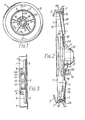
- the reference numeral 1 indicates generally a wheel assembly consisting of a metal wheel 2 and tire 3. While the present invention is described in conjunction with a vehicle wheel such is not to be construed as a limitation since the present balancing device is also advantageously used on other wheel assemblies.
- the automotive type wheel is indicated at 2 and is typically shouldered at 2A for tire bead retention.
- a metal disc 5 generally conical in shape and having a perimetrical flange 6. Said flange is enlarged at spaced intervals as at 6A (Fig.3) and thereat in securement with a rim 7 as by spot welds at 8.
- Corresponding openings 10 and 11 in flange portions 6A and the rim serve to admit gripper teeth 12 which may be interconnected by a flexible intermediate segment 13 secured in place by a rivet 14.
- the gripper teeth 12 may reflex inwardly as their pointed ends come into biased engagement with wheel shoulder 2A during mounting of the device.
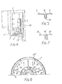
- disc 5 With attention again to disc 5, the same is configured so as to define radiating grooves 14 closed by webs 15 (Fig. 5).
- An annular recessed area of the disc is indicated at 16 with other such areas (not shown) provided primarily for aesthetic purposes.
- Webs 15 of disc 5 are flexible by reason of a reduced wall thickness which may be approximately .032 thousandths of an inch.
- the disc is of steel apporoximately .048 thousandsths of an inch with apertures formed adjacent the disc's inner periphery 17 for the reception of fastener assemblies 18.
- Non-metallic spacers at 20 isolate the metallic disc from the outer surface of a skirt portion 23 of a hub 21.
- Disc 5 defines openings intermediate pairs of grooves 14 for valve stem access and brake cooling purposes.
- Hub 21 includes a central portion, the conical skirt 23 integral therewith and an annular wall 24.
- Conical skirt 23 has an outer or disc facing surface in the shape of a truncated cone with a taper of approximately six degrees relative a plane normal to the wheel assembly axis.
- the skirt is apertured to receive the bolts of fastener assemblies 18 which attach disc 5 which also is of like conical shape.
- the mass of the balancing device is offset outwardly, or to the right in Figure 2, from a circular line of contact between the disc flange'6 and rim 7.
- the hub 21 and rim ? are formed from steel having a thickness of .048.
- the rim 7 is of a size to fit within that area proximate shoulder 2A of automotive wheel 2 with a clearance of about . 250 or less.
- FIG. 6 a modified wheel cover is illustrated wherein the unitary disc 5 has been dispensed with and instead, a series of sectors 26 support a hub 21'.
- the web at 15 in the first described form of the invention is dispensed with as indicated by a comparison of Figure 5 with Figure ?.
- the remaining details of the modified wheel cover remain as earlier described with like parts being indicated by prime reference numerals.
- a retainer assembly In some uses of the present balancing attachment where the wheel to which the attachment is applied is subject to severe impacts and strains it may be desired to employ a retainer assembly. Such assembly also enables installation of the present device on wheels not of ordinary or “stock” configuration such as those termed “deep dish” wheels and characterized by having a wheel hub portion axially offset an extreme distance from the wheel vertical centerline.
- the retainer assembly is of spider configuration having angular legs at 31 for securement at their turned outer ends to wheel lugs 32 by means of lug nuts 33. Said legs converge outwardly along the wheel axis and are formed with a lip 31A for attachment to a plate 34. Said plate is apertured at 34A-34B to permit alternate attachment of a leg 31 to permit installation of the retainer assembly on five bolt wheels wherein the wheel lugs are not diametric.
- a fastener at 35 connects each leg to plate 34.
- a hub retainer 36 Carried by plate 34 in an adjustable and lockable manner is a hub retainer 36 in the form of a headed fastener having an enlarged head 36A and a threaded shank in locked threaded engagement with a plate 34 which includes a threaded fastener element 38.
- the hub 21 is centrally apertured to receive retainer 36 with hub axial movement, as later explained, permitted intermediate the retainer extremities.
- a nut 39 limits hub outward movement in case of separation of the device from a wheel.
- the expansible means disclosed as a continuous rim when static, is disposed adjacent a circular outer portion of the wheel. Wheel rotation during vehicle travel results in the present device being subjected to centrifugal force acting along vectors perpendicular to the wheel axis.
- Conical disc 5, or the inclined flexible sectors in the modified form of the invention tend to move toward a plane normal to the wheel axis. Radially exerted loading of rim ? by said disc (or sectors) results in said rim uniformly expanding according to its modulus of elasticity and loading the circular wheel area to oppose vibratory motion of the wheel assembly otherwise occurring from the unbalanced condition of the wheel.
- disc 5 is separated into a plurality of radial sectors by the radiating grooves 14.
- the reduced thickness of web 15 allows for relative flexure of the sectors while in the second embodiment the sectors 26 are separated by the radial slots 14' ( Figure 7) and are therefore free to flex independent and/or relative to each other.
- a weak spring or no spring at all is used to join the sectors.
- the sectors appear to behave, therefore, as dynamically independent structural members tied at the center to the hub 21 and retained at the outer periphery by the cantilevered enlargements 6A of the flange 6.
- Each of the sectors being substantially triangular will have its center of mass radially outward of its half-way point of the sector radius. Furthermore, the sector center of mass is axially outboard off the plane extending through the attachments thereof to the rim 7 and with centrifugal loading outward collapse of the cantilevered flange enlargements 6A cumulates with the elastic hoop expansion of the rim to collapse the cone of the disc 5 even after full expansion of the rim.
- the cone angle of the disc 5 (or of sectors 26) is about 6 degrees.
- the ratio of inward collapse with radial expansion is therefore substantially equal to the ratio of the cosine of 6° to the sine of 6°.
- only small radial changes are necessary to axially collapse the cone.
Landscapes
- Engineering & Computer Science (AREA)
- Mechanical Engineering (AREA)
- General Engineering & Computer Science (AREA)
- Physics & Mathematics (AREA)
- Acoustics & Sound (AREA)
- Aviation & Aerospace Engineering (AREA)
- Testing Of Balance (AREA)
Priority Applications (4)
| Application Number | Priority Date | Filing Date | Title |
|---|---|---|---|
| US05/935,885 US4178041A (en) | 1979-09-20 | 1978-08-23 | Wheel attached balancing device |
| DE7979301955T DE2966892D1 (en) | 1979-09-20 | 1979-09-20 | Wheel attached balancing device |
| EP79301955A EP0025810B1 (de) | 1979-09-20 | 1979-09-20 | Am Rad angebrachte Auswuchtvorrichtung |
| AU51056/79A AU524595B2 (en) | 1979-09-20 | 1979-09-21 | Wheel attached balancing device |
Applications Claiming Priority (1)
| Application Number | Priority Date | Filing Date | Title |
|---|---|---|---|
| EP79301955A EP0025810B1 (de) | 1979-09-20 | 1979-09-20 | Am Rad angebrachte Auswuchtvorrichtung |
Publications (2)
| Publication Number | Publication Date |
|---|---|
| EP0025810A1 true EP0025810A1 (de) | 1981-04-01 |
| EP0025810B1 EP0025810B1 (de) | 1984-04-11 |
Family
ID=8186433
Family Applications (1)
| Application Number | Title | Priority Date | Filing Date |
|---|---|---|---|
| EP79301955A Expired EP0025810B1 (de) | 1979-09-20 | 1979-09-20 | Am Rad angebrachte Auswuchtvorrichtung |
Country Status (4)
| Country | Link |
|---|---|
| US (1) | US4178041A (de) |
| EP (1) | EP0025810B1 (de) |
| AU (1) | AU524595B2 (de) |
| DE (1) | DE2966892D1 (de) |
Cited By (1)
| Publication number | Priority date | Publication date | Assignee | Title |
|---|---|---|---|---|
| EP0041867A1 (de) * | 1980-06-09 | 1981-12-16 | Rush, Ellen As Administrator Of The Kim Rush Patent Trust | Wuchtungsausgleichzubehör an einem Fahrzeugrad |
Families Citing this family (8)
| Publication number | Priority date | Publication date | Assignee | Title |
|---|---|---|---|---|
| US4591210A (en) * | 1980-12-08 | 1986-05-27 | Nickoladze Leo G | Wheel balancing wheel cover |
| US4400037A (en) * | 1981-07-09 | 1983-08-23 | Gentry Herbert H | Wheel stabilizing device |
| FR2699453B1 (fr) * | 1992-12-21 | 1995-03-31 | Peugeot | Enjoliveur de roue pour véhicule automobile. |
| US5775176A (en) * | 1996-05-14 | 1998-07-07 | The Regents Of The University Of California | Separators for flywheel rotors |
| US6805413B2 (en) * | 2002-11-04 | 2004-10-19 | Kmc Wheel Company | E.X.O. rimwear |
| US7712840B2 (en) * | 2003-07-18 | 2010-05-11 | Fogal Sr Robert D | Uniformity and stabilizing system for a tire/wheel assembly |
| US8585155B2 (en) | 2010-04-16 | 2013-11-19 | Edison2 Llc | Method and system for forming a wheel structure |
| CN105363611B (zh) * | 2015-12-29 | 2017-12-19 | 中信戴卡股份有限公司 | 一种通用型车轮喷涂防护装置 |
Citations (6)
| Publication number | Priority date | Publication date | Assignee | Title |
|---|---|---|---|---|
| US2719756A (en) * | 1954-12-20 | 1955-10-04 | Jr John W Duke | Automatic wheel balancer |
| US2853344A (en) * | 1956-07-09 | 1958-09-23 | Vincent H Stout | Wheel balancing hub cap |
| US3048445A (en) * | 1958-03-24 | 1962-08-07 | Lyon Inc | Wheel cover |
| US3376075A (en) * | 1966-08-19 | 1968-04-02 | Awb Mfg Co | Dynamic wheel balancer |
| US3585962A (en) * | 1969-07-11 | 1971-06-22 | Karl O Vartia | Wheel balance indicator |
| US3662705A (en) * | 1971-04-23 | 1972-05-16 | Karl O Vartia | Speed controlled wheel balance indicator |
Family Cites Families (3)
| Publication number | Priority date | Publication date | Assignee | Title |
|---|---|---|---|---|
| US2895766A (en) * | 1956-03-06 | 1959-07-21 | Mechanical Controls Inc | Balancing device |
| DE2543203C3 (de) * | 1975-09-27 | 1980-03-13 | J.M. Voith Gmbh, 7920 Heidenheim | Walze für Papiermaschinen |
| GB1513468A (en) * | 1975-10-07 | 1978-06-07 | Chrysler Uk | Rotor balancing devices |
-
1978
- 1978-08-23 US US05/935,885 patent/US4178041A/en not_active Expired - Lifetime
-
1979
- 1979-09-20 EP EP79301955A patent/EP0025810B1/de not_active Expired
- 1979-09-20 DE DE7979301955T patent/DE2966892D1/de not_active Expired
- 1979-09-21 AU AU51056/79A patent/AU524595B2/en not_active Ceased
Patent Citations (6)
| Publication number | Priority date | Publication date | Assignee | Title |
|---|---|---|---|---|
| US2719756A (en) * | 1954-12-20 | 1955-10-04 | Jr John W Duke | Automatic wheel balancer |
| US2853344A (en) * | 1956-07-09 | 1958-09-23 | Vincent H Stout | Wheel balancing hub cap |
| US3048445A (en) * | 1958-03-24 | 1962-08-07 | Lyon Inc | Wheel cover |
| US3376075A (en) * | 1966-08-19 | 1968-04-02 | Awb Mfg Co | Dynamic wheel balancer |
| US3585962A (en) * | 1969-07-11 | 1971-06-22 | Karl O Vartia | Wheel balance indicator |
| US3662705A (en) * | 1971-04-23 | 1972-05-16 | Karl O Vartia | Speed controlled wheel balance indicator |
Cited By (1)
| Publication number | Priority date | Publication date | Assignee | Title |
|---|---|---|---|---|
| EP0041867A1 (de) * | 1980-06-09 | 1981-12-16 | Rush, Ellen As Administrator Of The Kim Rush Patent Trust | Wuchtungsausgleichzubehör an einem Fahrzeugrad |
Also Published As
| Publication number | Publication date |
|---|---|
| AU5105679A (en) | 1981-03-26 |
| AU524595B2 (en) | 1982-09-23 |
| DE2966892D1 (en) | 1984-05-17 |
| US4178041A (en) | 1979-12-11 |
| EP0025810B1 (de) | 1984-04-11 |
Similar Documents
| Publication | Publication Date | Title |
|---|---|---|
| US3799619A (en) | Vibration dampening assembly | |
| US3990491A (en) | Safety support device and rim for pneumatic tires | |
| US4817984A (en) | Vehicle suspension system | |
| US4699431A (en) | Piloted wheel assembly | |
| US4269451A (en) | Wheel and tire balancing system | |
| US5503464A (en) | Self-balancing wheel for motorized vehicles | |
| JPH0217363B2 (de) | ||
| US4178041A (en) | Wheel attached balancing device | |
| US4770220A (en) | High strength three-piece wheel | |
| US4755006A (en) | Dynamic wheel balancing device | |
| US2336920A (en) | Wheel balancing ring | |
| US3724904A (en) | Wheel balancing device | |
| US4268090A (en) | Imbalance compensating vehicle wheel attachment | |
| US6238006B1 (en) | Vehicle wheel having a balance weight retention shoulder | |
| CN205631990U (zh) | 具有增强防磨功能的轮毂以及汽车车轮 | |
| US6626580B2 (en) | Wheel bearing assembly | |
| US3047339A (en) | Wheel balancer | |
| US3017224A (en) | Wheel-balancing assembly for truck wheels and the like | |
| KR940008160B1 (ko) | 비공압식 회선 원추형 경량 차륜 | |
| US5772805A (en) | Wheel safety rim | |
| US6983998B2 (en) | Wheel cover for covering the rim of a vehicle wheel | |
| US6676224B2 (en) | Wheel balancing device for a tire-wheel assembly | |
| CA1122242A (en) | Wheel attached balancing device | |
| US3046058A (en) | Gyrostatic wheel stabilizing apparatus | |
| JPH05338401A (ja) | ディスクホイール |
Legal Events
| Date | Code | Title | Description |
|---|---|---|---|
| PUAI | Public reference made under article 153(3) epc to a published international application that has entered the european phase |
Free format text: ORIGINAL CODE: 0009012 |
|
| AK | Designated contracting states |
Designated state(s): BE DE FR GB IT NL SE |
|
| 17P | Request for examination filed |
Effective date: 19810929 |
|
| GRAA | (expected) grant |
Free format text: ORIGINAL CODE: 0009210 |
|
| RAP1 | Party data changed (applicant data changed or rights of an application transferred) |
Owner name: GYROSCOPIC WHEEL COVER TRUST |
|
| AK | Designated contracting states |
Designated state(s): BE DE FR GB IT NL SE |
|
| PG25 | Lapsed in a contracting state [announced via postgrant information from national office to epo] |
Ref country code: IT Free format text: LAPSE BECAUSE OF FAILURE TO SUBMIT A TRANSLATION OF THE DESCRIPTION OR TO PAY THE FEE WITHIN THE PRESCRIBED TIME-LIMIT;WARNING: LAPSES OF ITALIAN PATENTS WITH EFFECTIVE DATE BEFORE 2007 MAY HAVE OCCURRED AT ANY TIME BEFORE 2007. THE CORRECT EFFECTIVE DATE MAY BE DIFFERENT FROM THE ONE RECORDED. Effective date: 19840411 |
|
| REF | Corresponds to: |
Ref document number: 2966892 Country of ref document: DE Date of ref document: 19840517 |
|
| ET | Fr: translation filed | ||
| PGFP | Annual fee paid to national office [announced via postgrant information from national office to epo] |
Ref country code: FR Payment date: 19840928 Year of fee payment: 6 |
|
| PGFP | Annual fee paid to national office [announced via postgrant information from national office to epo] |
Ref country code: SE Payment date: 19840930 Year of fee payment: 6 Ref country code: BE Payment date: 19840930 Year of fee payment: 6 |
|
| PGFP | Annual fee paid to national office [announced via postgrant information from national office to epo] |
Ref country code: DE Payment date: 19841124 Year of fee payment: 6 |
|
| PLBE | No opposition filed within time limit |
Free format text: ORIGINAL CODE: 0009261 |
|
| STAA | Information on the status of an ep patent application or granted ep patent |
Free format text: STATUS: NO OPPOSITION FILED WITHIN TIME LIMIT |
|
| 26N | No opposition filed | ||
| PGFP | Annual fee paid to national office [announced via postgrant information from national office to epo] |
Ref country code: NL Payment date: 19850930 Year of fee payment: 7 |
|
| PG25 | Lapsed in a contracting state [announced via postgrant information from national office to epo] |
Ref country code: SE Effective date: 19860921 |
|
| PG25 | Lapsed in a contracting state [announced via postgrant information from national office to epo] |
Ref country code: BE Effective date: 19860930 |
|
| BERE | Be: lapsed |
Owner name: GYROSCOPIC WHEEL COVER TRUST Effective date: 19860930 |
|
| PG25 | Lapsed in a contracting state [announced via postgrant information from national office to epo] |
Ref country code: NL Effective date: 19870401 |
|
| NLV4 | Nl: lapsed or anulled due to non-payment of the annual fee | ||
| PG25 | Lapsed in a contracting state [announced via postgrant information from national office to epo] |
Ref country code: FR Free format text: LAPSE BECAUSE OF NON-PAYMENT OF DUE FEES Effective date: 19870527 |
|
| PG25 | Lapsed in a contracting state [announced via postgrant information from national office to epo] |
Ref country code: DE Effective date: 19870602 |
|
| GBPC | Gb: european patent ceased through non-payment of renewal fee | ||
| REG | Reference to a national code |
Ref country code: FR Ref legal event code: ST |
|
| PG25 | Lapsed in a contracting state [announced via postgrant information from national office to epo] |
Ref country code: GB Effective date: 19881118 |
|
| EUG | Se: european patent has lapsed |
Ref document number: 79301955.5 Effective date: 19870812 |