EP0026128A1 - Dispositif d'enregistrement holographique et système optique de traitement d'information comportant un tel dispositif - Google Patents
Dispositif d'enregistrement holographique et système optique de traitement d'information comportant un tel dispositif Download PDFInfo
- Publication number
- EP0026128A1 EP0026128A1 EP80401283A EP80401283A EP0026128A1 EP 0026128 A1 EP0026128 A1 EP 0026128A1 EP 80401283 A EP80401283 A EP 80401283A EP 80401283 A EP80401283 A EP 80401283A EP 0026128 A1 EP0026128 A1 EP 0026128A1
- Authority
- EP
- European Patent Office
- Prior art keywords
- wave
- sigma
- object wave
- holographic
- amplified
- Prior art date
- Legal status (The legal status is an assumption and is not a legal conclusion. Google has not performed a legal analysis and makes no representation as to the accuracy of the status listed.)
- Granted
Links
Images
Classifications
-
- G—PHYSICS
- G03—PHOTOGRAPHY; CINEMATOGRAPHY; ANALOGOUS TECHNIQUES USING WAVES OTHER THAN OPTICAL WAVES; ELECTROGRAPHY; HOLOGRAPHY
- G03H—HOLOGRAPHIC PROCESSES OR APPARATUS
- G03H1/00—Holographic processes or apparatus using light, infrared or ultraviolet waves for obtaining holograms or for obtaining an image from them; Details peculiar thereto
-
- G—PHYSICS
- G02—OPTICS
- G02F—OPTICAL DEVICES OR ARRANGEMENTS FOR THE CONTROL OF LIGHT BY MODIFICATION OF THE OPTICAL PROPERTIES OF THE MEDIA OF THE ELEMENTS INVOLVED THEREIN; NON-LINEAR OPTICS; FREQUENCY-CHANGING OF LIGHT; OPTICAL LOGIC ELEMENTS; OPTICAL ANALOGUE/DIGITAL CONVERTERS
- G02F1/00—Devices or arrangements for the control of the intensity, colour, phase, polarisation or direction of light arriving from an independent light source, e.g. switching, gating or modulating; Non-linear optics
- G02F1/35—Non-linear optics
- G02F1/353—Frequency conversion, i.e. wherein a light beam is generated with frequency components different from those of the incident light beams
- G02F1/3536—Four-wave interaction
- G02F1/3538—Four-wave interaction for optical phase conjugation
Definitions
- the invention relates to the field of holographic recording and more particularly relates to a holographic recording device with amplification of the object wave and an information processing system comprising such a device.
- the hologram of an object is recorded from the object wave diffracted by the object whose hologram is to be recorded and from a corresponding reference wave.
- the contrast of the fringes recorded being such that the reproduction of an image of the object by means of a restitution wavefront is carried out in good conditions, it is necessary to use an object wavefront which before lighting the object is sufficiently energetic for the diffracted object wavefront to interfere with the reference wavefront in the support d holographic recording in good conditions.
- a compromise must be found between the energy transported by the object beam and the qualities of the recording medium in order to obtain a good quality image.
- Conventional photosensitive media capable of being used as holographic recording media can reach large areas, but in this case they have only average optical qualities and require a large energy to obtain a correct image. registration.
- the source used must have a sufficient coherence length so that the recording of the fringes, obtained by superposition in the material of the object and reference wave fronts, is carried out under conditions optimum in terms of their contrast.
- the subject of the invention is a holographic recording device making it possible to record holograms of objects of very large area using photosensitive supports of medium quality but available in large dimensions, this device requiring only one source having a reduced coherence length.
- the holographic recording device comprising a light source, an optical device forming from the light wave emitted by the source an object wave and a reference wave, and a holographic recording medium
- a holographic recording medium is mainly characterized in that it further comprises an amplification device receiving the object wave diffracted by the object to be analyzed and two contra-progressive pumping waves in the amplification device of the same frequency as the object wave to generate an amplified wave conjugate of the object wave, the recording device further comprising optical means directing the amplified wave and the wave reference to the holographic medium for recording.
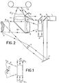
- FIG. 1 schematically represents an amplification cell usable in the recording device according to the invention
- FIG. 2 schematically represents the holographic recording device according to the invention.
- the first problem to be solved is the illumination of the object; in fact, for the wave diffracted by the object to be able to be used to interfere with the reference wave in the recording medium, the energy transported by this wave and picked up by the optical system must be sufficient, which can only be achieved with an incident object beam of very high energy when the wave surface is very large. In fact, only a very small part of the radiation is captured, of the order of 10 -3 to 10 -4 times the incident energy.
- the device according to the invention comprises a device for amplifying the wavefront diffracted by the object, the amplified wavefront only being then directed towards the holographic recording medium to interfere with the reference wavefront.
- the incident beam on the object can transport only a rather weak energy, and however the holographic recording is obtained in very good conditions on a conventional holographic support.
- the wave ⁇ 4 is amplified with respect to the incident wave ⁇ o , this amplification being effected by energy transfer from the pump waves towards the conjugate wave of the incident object wave.
- the two pumping waves E 2 and ⁇ 3 are sufficiently energetic, so that the dielectric polarization of the material induced by these high intensity electric fields allows non-linear mixing to transfer energy to the front. conjugate wave.
- the non-linear interaction medium can be a sodium vapor or carbon sulfide CS2 cell for example.
- the medium behaves like a multimodal image amplifier in which phase adaptation is always carried out.
- Such a nonlinear amplification cell has no remanence effect, the reproduction of a conjugate wavefront of the incident wavefront can therefore be obtained continuously for an unlimited period.
- Such a property is particularly advantageous when it is desired to carry out a succession of holographic recordings corresponding to images of a moving object, the wave front diffracted by the object varying continuously and the wave front conjugate amplified by the non-linear amplification cell then following the same variations.
- the holographic recording device shown in FIG. 2 includes such an amplification device.
- This recording device comprises a laser source 1 from which all the useful beams are formed, ie the beam incident on the object, the "pump" beams, for the non-linear amplification device, and the reference beam directed towards the holographic recording medium.
- the optical device making it possible to form these different beams is described below without limitation. It includes a beam splitter making it possible to form the incident beam on the object by reflection; this beam is directed towards the object 5 by means of a mirror 3 and the necessary opening is given to it by a lens 4.
- the beam diffracted by the object 5, whose wave surface is L, is directed towards the non-linear amplification cell through a converging lens 6.
- the amplification cell 7 also receives the pump beams obtained by reflection on the beam splitter 8 of the beam transmitted by the beam splitter 2.
- the device comprises a deflection mirror 9 returning to the non-linear interaction medium the beam which has passed through this same medium.
- the wavefront resulting from the nonlinear interaction is, as explained above above, a wavefront conjugate of the wavefront incident on the amplification cell, that is to say propagating in an opposite direction but having the same shape, amplifies with respect to the object wavefront.
- the corresponding beam passes through the lens 6, is reflected by a beam splitter 10 and directed towards a holographic recording medium 12 through an optical system shown in the figure in the form of a converging lens 11.
- This recording device is such that the coherence length of the laser source 1 can be reduced compared to a conventional device; in fact, this coherence length is to be assessed by the differences in propagation length between the reference beam and the amplified beam at the time of the holographic inscription.
- the photosensitive support 12 used can be a conventional support of photographic emulsion type; in this case, a development phase must be planned, before the recorded object wavefront can be restored by exposure to restoring radiation.
- Such a recording device can be used in a system for displaying deformations of structures in motion by holographic interferometry, for the non-destructive control of these structures.
- a hologram of an object is recorded at a given instant, and a holographic image is restored from the hologram at another moment; interference is created by interferometry between the restored wave front and a comparison wave front corresponding for example to the image of the non-deformed object, these interferences representing the deformations undergone by the structure between the two states corresponding to two wave fronts.
- interferometry can be "in real time", that is to say that a restored holographic image forming a reference wave surface is superimposed on the object itself.
- interferometry can also be by "double exposure", the interference fringes corresponding to the deformation being obtained by superposition at a given instant of two holographic images restored simultaneously corresponding to holograms recorded at different times.
- the holographic recording device can also be used for example in optical information processing systems such as optical correlators.
- the invention is not limited to the embodiment precisely described.
- the light source used can be a pulsed or continuous laser, the amplification cell operating with two types of source.
- the optical device shown to form the different useful beams is only one possible embodiment.
- the amplification cell may comprise another material having a suitable non-linear susceptibility coefficient, for example carbon sulfide or germanium.
Landscapes
- Physics & Mathematics (AREA)
- Nonlinear Science (AREA)
- General Physics & Mathematics (AREA)
- Optics & Photonics (AREA)
- Holo Graphy (AREA)
- Lasers (AREA)
Abstract
Description
- L'invention se rapporte au domaine de l'enregistrement holographique et a plus particulièrement pour objet un dispositif d'enregistrement holographique avec amplification de l'onde objet et un système de traitement d'information comportant un tel dispositif.
- Dans les dispositifs d'enregistrement holographiques connus, l'hologramme d'un objet est enregistré à partir de l'onde objet diffractée par l'objet dont on souhaite enregistrer l'hologramme et d'une onde de référence correspondante. D'une manière générale, pour que l'hologramme ainsi enregistré soit de bonne qualité, le contraste des franges enregistrées étant tel que la restitution d'une image de l'objet au moyen d'un front d'onde de restitution soit effectuée dans de bonnes conditions, il est nécessaire d'utiliser un front d'onde objet qui avant éclairement de l'objet soit suffi- sament énergétique pour que le front d'onde objet diffracté interfère avec le front d'onde de référence dans le support d'enregistrement holographique dans de bonnes conditions. En général un compromis doit être trouvé entre l'énergie transportée par le faisceau objet et les qualités du support d'enregistrement pour obtenir une image de bonne qualité.
- Les supports photosensibles conventionnele susceptibles d'être utilisés comme supports d'enregistrement holographique peuvent atteindre de grandes surfaces mais ils n'ont dans ce cas, que des qualités optiques moyennes et nécessitent pour l'obtention d'une image correcte une grande énergie d'inscription.
- Des supports beaucoup plus performants, présentant une très haute résolution et ne nécessitant qu'une énergie d'inscription assez faible, ont été mis au point par exemple les cristaux électro-optiques et photoconducteurs type BSO, mais ils ne sont obtenus qu'en petites surfaces et ne peuvent donc permettre l'enregistrement tridimensionnel d'objets de très grandes surfaces.
- De plus, dans les dispositifs d'enregistrement holographique usuels, la source utilisée doit avoir une longueur de cohérence suffisante pour que l'enregistrement des franges, obtenues par superposition dans le matériau des fronts d'onde objet et référence, soit effectué dans des conditions optimum quant à leur contraste.
- L'invention a pour objet un dispositif d'enregistrement holographique permettant d'effectuer l'enregistrement d'hologrammes d'objets de très grande surface en utilisant des supports photosensibles de qualité moyenne mais disponibles en grandes dimensions, ce dispositif ne nécessitant qu'une source ayant une longueur de cohérence réduite.
- Suivant l'invention, le dispositif d'enregistrement holographique comportant une source lumineuse, un dispositif optique formant à partir de l'onde lumineuse émise par la source une onde objet et une onde de référence,et un support d'enregistrement holographique, est principalement caractérisé en ce qu'il comporte en outre un dispositif d'amplification recevant l'onde objet diffractée par l'objet à analyser et deux ondes de pompage contra-progressives dans le dispositif d'amplification de même fréquence que l'onde objet pour générer une onde amplifiée conjuguée de l'onde objet, le dispositif d'enregistrement comportant de plus des moyens optiques dirigeant l'onde amplifiée et l'onde de référence vers le support holographique pour l'enregistrement.
- L'invention sera mieux comprise et d'autres caractéristiques apparaîtront à l'aide de la description qui suit en référence aux figures annexées.
- La figure 1 représente schématiquement une cellule d'amplification utilisable dans le dispositif d'enregistrement selon l'invention ;
- La figure 2 représente schématiquement le dispositif d'enregistrement holographique selon l'invention.
- Pour l'enregistrement d'hologrammes d'objets de grande surface, le premier problème à résoudre est l'éclairement de l'objet ; en effet, pour que l'onde diffractée par l'objet puisse être utilisée pour interférer avec l'onde de référence dans le support d'enregistrement, il faut que l'énergie transportée par cette onde et captée par le système optique soit suffisante, ce qui ne peut être réalisé qu'avec un faisceau objet incident de très grande énergie lorsque la surface d'onde est très étendue. En effet, seule une très faible partie du rayonnement est captée,de l'ordre de 10-3 à 10-4 fois l'énergie incidente.
- Pour éviter ce problème, le dispositif selon l'invention comporte un dispositif d'amplification du front d'onde diffracté par l'objet, le front d'onde amplifié étant seulement alors dirigé vers le support d'enregistrement holographique pour y interférer avec le front d'onde de référence.
- Du fait de cette amplification, le faisceau incident sur l'objet peut ne transporter qu'une énergie assez faible, et cependant l'enregistrement holographique est obtenu dans de très bonnes conditions sur un support holographique conventionnel.
- Le dispositif d'amplification représenté schématiquement sur la figure 1, comporte un milieu d'intéraction non linéaire tel qu'une onde objet incidente Σo de vecteur d'onde
K 1 et deux ondes de "pompe" planes Σ2 et Σ3 de même longueur d'onde que l'onde objet de vecteurs d'ondeK 2 etK 3 tels queK 2 +K 3 = 0 (se propageant donc dans des directions opposées), interagissent dans le milieu non linéaire pour générer une onde Σ4 de vecteur d'ondeK 4 conjuguée de l'onde objet incidente Σo. Lorsque le coefficient de couplage du milieu d'interaction et la longueur d'interaction sont convenablement choisis, l'onde Σ4 est amplifiée par rapport à l'onde incidente Σo, cette amplification s'effectuant par transfert d'énergie des ondes pompes vers l'onde conjuguée de l'onde objet incidente. Pour cela, il est nécessaire que les deux ondes de pompage E 2 et Σ3 soient suffisamment énergétiques, de façon que la polarisation diélectrique du matériau induite par ces champs électriques de grandes intensités permette par mélange non linéaire le transfert d'énergie vers le front d'onde conjugué. - Le milieu d'interaction non linéaire peut être une cellule à vapeur de sodium ou à sulfure de carbone CS2 par exemple. Dans un tel milieu, avec des ondes de longueur d'onde X= 5890 A, lorsque la longueur d'interaction est L = 5 cm et que les faisceaux pompe ont une intensité de l'ordre de 40 KW/cm2, la source étant un laser pulsé dont les impulsions lumineuses durent 6 ns, le coefficient d'amplification de l'onde conjuguée par rapport à l'onde incidente peut être de l'ordre de 100.
- Toutes les ondes ayant la même longueur d'onde, le milieu se comporte comme un amplificateur d'image mul- timode dans lequel l'adaptation de phase est toujours réalisée.
- Une telle cellule d'amplification non linéaire ne possède aucun effet de rémanence, la restitution d'un front d'onde conjugué du front d'onde incident peut donc être obtenue en continu pendant une durée non limitée. Une telle propriété est particulièrement intéressante lorsque l'on souhaite effectuer une succession d'enre- gistrementsholographiques correspondant à des images d'un objet en mouvement, le front d'onde diffracté par l'objet variant de manière continue et le front d'onde conjugué amplifié par la cellule d'amplification non linéaire suivant alors les mêmes variations.
- Le dispositif d'enregistrement holographique représenté sur la figure 2 comporte un tel dispositif d'amplification.
- Ce dispositif d'enregistrement comporte une source laser 1 à partir de laquelle sont formés tous les faisceaux utiles, c'est à dire le faisceau incident sur l'objet, les faisceaux "pompes", pour le dispositif d'amplification non linéaire, et le faisceau de référence dirigé vers le support d'enregistrement holographique. Le dispositif optique permettant de former ces différents faisceaux est décrit ci-après de manière non limitative. Il comporte un séparateur de faisceau permettant de former par réflexion le faisceau incident sur l'objet ; ce faisceau est dirigé vers l'otjet 5 au moyen d'un miroir 3 et l'ouverture nécessaire lui est donnée par une lentille 4. Le faisceau diffracté par l'objet 5, dont la surface d'onde est L, est dirigé vers la cellule d'amplification non linéaire à travers une lentille convergente 6. La cellule d'amplification 7 reçoit également les faisceaux pompes obtenus par réflexion sur le séparateur de faisceau 8 du faisceau transmis par le séparateur de faisceau 2. Pour obtenir deux faisceaux pompes dont les vecteurs d'onde soient opposés, le dispositif comporte un miroir de renvoi 9 renvoyant vers le milieu d'interaction non linéaire le faisceau qui a traversé ce même milieu. Le front d'onde résultant de l'interaction non linéaire est, comme expliqué ci-dessus, un front d'onde conjugué du front d'onde incident sur la cellule d'amplification, c'est-à-dire se propageant dans une direction opposée mais ayant la même forme, amplifie par rapport au front d'onde objet.
- Le faisceau correspondant traverse la lentille 6, est réfléchi par un séparateur de faisceau 10 et dirigé vers un support d'enregistrement holographique 12 à travers un système optique représenté sur la figure sous la forme d'une lentille convergente 11. Le front d'onde Σ'oincident sur le support holographique et comportant toutes les informations relatives à l'objet, y interfère avec un faisceau de référence dont la surface ER d'onde est plane ; ce faisceau de référence est le faisceau transmis par le séparateur de faisceau 8 et réfléchi par un miroir plan 13. Ce dispositif d'enregistrement est tel que la longueur de cohérence de la source laser 1 peut être réduite par rapport a un dispositif conventionnel ; en effet, cette longueur de cohérence est à apprécier par les différences de longueur de propagation entre le faisceau de référence et le faisceau amplifié au moment de l'inscription holographique. Le support photosensible 12 utilisé peut être un support classique type émulsion photographique ; dans ce cas, une phase de développement doit être prévue, avant que le front d'onde objet enregistrée puisse être restitué par exposition à un rayonnement de restitution.
- Un tel dispositif d'enregistrement peut être utilisé dans un système de visualisation de déformations de structures en mouvement par interférométrie holographique, pour le contrôle non destructif de ces structures.
- En effet, dans de tels systèmes, un hologramme d'un objet est enregistré à un instant donné, et une image holographique est restituée à partir de l'hologramme à un autre instant ; des interférences sont crées par interférométrie entre le front d'onde restitué et un front d'onde de comparaison correspondant par exemple à l'image de l'objet non déformé, ces interférences représentant les déformations subies par la structure entre les deux états correspondant aux deux fronts d'onde. Ces systèmes-de visualisation peuvent mettre en oeuvre différentes méthodes : l'interférométrie peut être "en temps réel", c'est-à-dire qu'une image holographique restituée formant surface d'onde de référence est superposée à l'objet lui-même, les franges crées par cette superposition étant caractéristiques de la déformation du front d'onde et les variations de ces franges dans le temps observables en temps réel suivant les déformations de la structure ; l'interférométrie peut également être par "double exposition", les franges d'interférence correspondant à la déformation étant obtenues par superposition à un instant donné de deux images holographiques restituées simultanément correspondant à des hologrammes enregistrés à des instants différents.
- Compte tenu de l'amplification de l'onde objet, des hologrammes d'objets de grandes dimensions peuvent être obtenus et toutes les opérations d'optique cohérente utilisant des fronts d'onde restitués à partir d'hologrammes deviennent possibles pour de tels objets.
- Le dispositif d'enregistrement holographique peut également être utilisé par exemple dans les systèmes optiques de traitement d'information type corrélateurs optiques.
- L'invention n'est pas limitée au mode de réalisation précisément décrit. En particulier, la source de lumière utilisée peut être un laser pulsé ou continu, la cellule d'amplification fonctionnant avec des deux types de source. De plus, comme indiqué ci-dessus, le dispositif optique représenté pour former les différents faisceaux utiles n'est qu'un mode de réalisation possible.
- Enfin la cellule d'amplification peut comporter un autre matériau ayant un coefficient de susceptibilité non linéaire convenable, par exemple du sulfure de carbone ou du germanium.
Claims (5)
Applications Claiming Priority (2)
| Application Number | Priority Date | Filing Date | Title |
|---|---|---|---|
| FR7923597 | 1979-09-21 | ||
| FR7923597A FR2466042A1 (fr) | 1979-09-21 | 1979-09-21 | Dispositif d'enregistrement holographique et systeme optique de traitement d'information comportant un tel dispositif |
Publications (2)
| Publication Number | Publication Date |
|---|---|
| EP0026128A1 true EP0026128A1 (fr) | 1981-04-01 |
| EP0026128B1 EP0026128B1 (fr) | 1983-12-14 |
Family
ID=9229904
Family Applications (1)
| Application Number | Title | Priority Date | Filing Date |
|---|---|---|---|
| EP80401283A Expired EP0026128B1 (fr) | 1979-09-21 | 1980-09-09 | Dispositif d'enregistrement holographique et système optique de traitement d'information comportant un tel dispositif |
Country Status (4)
| Country | Link |
|---|---|
| EP (1) | EP0026128B1 (fr) |
| JP (1) | JPS5655980A (fr) |
| DE (1) | DE3065893D1 (fr) |
| FR (1) | FR2466042A1 (fr) |
Cited By (4)
| Publication number | Priority date | Publication date | Assignee | Title |
|---|---|---|---|---|
| FR2503862A1 (fr) * | 1981-04-08 | 1982-10-15 | Centre Nat Rech Scient | Dispositif optique interferometrique avec miroir(s) a conjugaison de phase, en particulier pour gyrometre laser |
| FR2516232A1 (fr) * | 1981-11-09 | 1983-05-13 | Thomson Csf | Interferometre de type michelson a miroir photorefractif |
| FR2520521A1 (fr) * | 1982-01-26 | 1983-07-29 | Thomson Csf | Dispositif de cinema par holographie |
| EP0271339A3 (en) * | 1986-12-11 | 1989-06-07 | Hamamatsu Photonics K.K. | An apparatus for optically analyzing an object using four-wave mixing technique |
Families Citing this family (1)
| Publication number | Priority date | Publication date | Assignee | Title |
|---|---|---|---|---|
| US4674824A (en) * | 1985-06-14 | 1987-06-23 | Stanford University | System for enhancement of optical features |
Citations (2)
| Publication number | Priority date | Publication date | Assignee | Title |
|---|---|---|---|---|
| US3542452A (en) * | 1967-03-20 | 1970-11-24 | Rca Corp | Transitory hologram apparatus |
| US3604604A (en) * | 1970-02-24 | 1971-09-14 | Albert D Ahn | Invalid{3 s sock-holding appliance |
-
1979
- 1979-09-21 FR FR7923597A patent/FR2466042A1/fr active Granted
-
1980
- 1980-09-09 DE DE8080401283T patent/DE3065893D1/de not_active Expired
- 1980-09-09 EP EP80401283A patent/EP0026128B1/fr not_active Expired
- 1980-09-22 JP JP13084880A patent/JPS5655980A/ja active Pending
Patent Citations (2)
| Publication number | Priority date | Publication date | Assignee | Title |
|---|---|---|---|---|
| US3542452A (en) * | 1967-03-20 | 1970-11-24 | Rca Corp | Transitory hologram apparatus |
| US3604604A (en) * | 1970-02-24 | 1971-09-14 | Albert D Ahn | Invalid{3 s sock-holding appliance |
Non-Patent Citations (6)
| Title |
|---|
| APPLIED PHYSICS LETTERS, vol. 31, no. 9, 1er novembre 1977, New York US, D. BLOOM ET AL.: "Conjugate wave front generation and image reconstruction by four wave mixing" pages 592-594 * |
| APPLIED PHYSICS LETTERS, vol. 32, no. 12, 15 juin 1978, New York US, P. LIAO et al.: "CW optical wave front conjugation by saturated absorption atomic sodium vapor" pages 813-815 * |
| IEEE JOURNAL OF QUANTUM ELECTRONICS, vol. QE-14, no. 9, septembre 1978 New York US, A. YARIV: "Phase conjugate optics and real time holography", pages 650-660 * |
| OPTICS LETTERS, vol. 2, no. 3, mars 1978, New York US, D. Bloom et al.: "Observation of amplified reflection by degenerate four wave mixing in atomic sodium vapor", pages 58-60 * |
| OPTICS LETTERS, vol. 4, no. 1, janvier 1979 New York US, J. HUIGNARD et al.: "Phase conjugate wavefront generation via real time holography in Bi12SiO20 crystals", pages 21-23 * |
| PROCEEDINGS OF THE 1978 INTERNATIONAL OPTICAL COMPUTING CONFERENCE, septembre 5-7, 1978, London GB, 1979 IEEE New York US, J. HUIGNARD et al.: "Bismuth Silicon Oxyde crystals and applications Real time holographic recordings", pages 21-24 * |
Cited By (9)
| Publication number | Priority date | Publication date | Assignee | Title |
|---|---|---|---|---|
| FR2503862A1 (fr) * | 1981-04-08 | 1982-10-15 | Centre Nat Rech Scient | Dispositif optique interferometrique avec miroir(s) a conjugaison de phase, en particulier pour gyrometre laser |
| EP0063977A1 (fr) * | 1981-04-08 | 1982-11-03 | Etablissement Public dit: CENTRE NATIONAL DE LA RECHERCHE SCIENTIFIQUE (CNRS) | Dispositif optique interférométrique avec miroir(s) à conjugaison de phase, en particulier pour gyromètre laser |
| US4575245A (en) * | 1981-04-08 | 1986-03-11 | Centre National De La Recherche Scientifique (C.N.R.S.) | Interferometric optical devices with phase conjugating mirrors in particular for laser gyrometers |
| FR2516232A1 (fr) * | 1981-11-09 | 1983-05-13 | Thomson Csf | Interferometre de type michelson a miroir photorefractif |
| EP0079268A1 (fr) * | 1981-11-09 | 1983-05-18 | Thomson-Csf | Interferomètre de type Michelson à miroir photoréfractif |
| US4571080A (en) * | 1981-11-09 | 1986-02-18 | Thomson-Csf | Michelson interferometer with a photorefractive mirror |
| FR2520521A1 (fr) * | 1982-01-26 | 1983-07-29 | Thomson Csf | Dispositif de cinema par holographie |
| EP0084996A3 (fr) * | 1982-01-26 | 1983-08-17 | Thomson-Csf | Dispositif de cinéma par holographie |
| EP0271339A3 (en) * | 1986-12-11 | 1989-06-07 | Hamamatsu Photonics K.K. | An apparatus for optically analyzing an object using four-wave mixing technique |
Also Published As
| Publication number | Publication date |
|---|---|
| FR2466042B1 (fr) | 1981-09-11 |
| DE3065893D1 (en) | 1984-01-19 |
| EP0026128B1 (fr) | 1983-12-14 |
| FR2466042A1 (fr) | 1981-03-27 |
| JPS5655980A (en) | 1981-05-16 |
Similar Documents
| Publication | Publication Date | Title |
|---|---|---|
| EP0040114B1 (fr) | Système optique d'observation en temps réél à balayage | |
| EP0067082B1 (fr) | Source cohérente de rayonnement générant un faisceau de direction de propagation réglable | |
| US5148323A (en) | Local reference beam generator | |
| EP0138668B1 (fr) | Dispositif d'enregistrement d'une image cohérente dans une cavité optique multimode | |
| EP0120737A1 (fr) | Hydrophone à fibre optique | |
| WO2016110581A1 (fr) | Capteur a fibre optique | |
| EP0028548A1 (fr) | Système de correlation optique en temps réel | |
| EP0053052B1 (fr) | Dispositif d'interférométrie pour la visualisation en temps réel des déformations de structures vibrantes | |
| EP0058592B1 (fr) | Dispositif optique transformateur de Fourier, et corrélateur optique mettant en oeuvre ce dispositif optique transformateur de Fourier | |
| FR2688899A1 (fr) | Procede de mesure du temps pour former un reseau d'indices de refraction d'un milieu photo-non lineaire. | |
| EP0095960A1 (fr) | Dispositif de mise en mémoire d'une image cohérente dans une cavité optique multimode | |
| US5018852A (en) | Motion detection, novelty filtering, and target tracking using an interferometric technique with GaAs phase conjugate mirror | |
| EP0559878B1 (fr) | Laser de puissance a deflexion | |
| EP0069652B1 (fr) | Procédé holographique d'enregistrement-lecture | |
| CN108957999B (zh) | 基于相位型涡旋透镜的相移全息装置及成像方法 | |
| EP0026128B1 (fr) | Dispositif d'enregistrement holographique et système optique de traitement d'information comportant un tel dispositif | |
| FR2460523A1 (fr) | Tete de lecture optique a source laser a semi-conducteur et dispositif de lecture par reflexion d'un support d'information comportant une telle tete optique | |
| EP0084996A2 (fr) | Dispositif de cinéma par holographie | |
| EP0069627B1 (fr) | Dispositif d'éclairage évolutif d'un objet | |
| EP0708509A1 (fr) | Dispositif d'émission mono-longueur d'onde | |
| EP0040116B1 (fr) | Dispositif de prise de vue à champ étendu | |
| US5233554A (en) | Programmable optical correlator | |
| EP0098185A1 (fr) | Dispositif d'éclairement d'un milieu électro-optique pour enregistrer des hologrammes en temps réel | |
| JP3066457B2 (ja) | 光学的パターン認識装置 | |
| Goodman | Digital image formation from holograms: Early motivation modern capabilities |
Legal Events
| Date | Code | Title | Description |
|---|---|---|---|
| PUAI | Public reference made under article 153(3) epc to a published international application that has entered the european phase |
Free format text: ORIGINAL CODE: 0009012 |
|
| AK | Designated contracting states |
Designated state(s): DE GB NL |
|
| 17P | Request for examination filed |
Effective date: 19810415 |
|
| GRAA | (expected) grant |
Free format text: ORIGINAL CODE: 0009210 |
|
| AK | Designated contracting states |
Designated state(s): DE GB NL |
|
| REF | Corresponds to: |
Ref document number: 3065893 Country of ref document: DE Date of ref document: 19840119 |
|
| PGFP | Annual fee paid to national office [announced via postgrant information from national office to epo] |
Ref country code: DE Payment date: 19840723 Year of fee payment: 5 |
|
| PLBE | No opposition filed within time limit |
Free format text: ORIGINAL CODE: 0009261 |
|
| STAA | Information on the status of an ep patent application or granted ep patent |
Free format text: STATUS: NO OPPOSITION FILED WITHIN TIME LIMIT |
|
| 26N | No opposition filed | ||
| PGFP | Annual fee paid to national office [announced via postgrant information from national office to epo] |
Ref country code: NL Payment date: 19850930 Year of fee payment: 6 |
|
| PG25 | Lapsed in a contracting state [announced via postgrant information from national office to epo] |
Ref country code: NL Effective date: 19870401 |
|
| NLV4 | Nl: lapsed or anulled due to non-payment of the annual fee | ||
| PG25 | Lapsed in a contracting state [announced via postgrant information from national office to epo] |
Ref country code: DE Effective date: 19870602 |
|
| GBPC | Gb: european patent ceased through non-payment of renewal fee | ||
| PG25 | Lapsed in a contracting state [announced via postgrant information from national office to epo] |
Ref country code: GB Effective date: 19881118 |