EP0026149B1 - Maschine zur Herstellung selbstgezwirnter Garne - Google Patents
Maschine zur Herstellung selbstgezwirnter Garne Download PDFInfo
- Publication number
- EP0026149B1 EP0026149B1 EP80420104A EP80420104A EP0026149B1 EP 0026149 B1 EP0026149 B1 EP 0026149B1 EP 80420104 A EP80420104 A EP 80420104A EP 80420104 A EP80420104 A EP 80420104A EP 0026149 B1 EP0026149 B1 EP 0026149B1
- Authority
- EP
- European Patent Office
- Prior art keywords
- self
- fact
- machine according
- yarns
- twisting
- Prior art date
- Legal status (The legal status is an assumption and is not a legal conclusion. Google has not performed a legal analysis and makes no representation as to the accuracy of the status listed.)
- Expired
Links
- 238000011282 treatment Methods 0.000 claims description 16
- 238000004804 winding Methods 0.000 claims description 7
- 230000000295 complement effect Effects 0.000 claims description 5
- 238000010438 heat treatment Methods 0.000 claims description 4
- 238000012545 processing Methods 0.000 description 13
- 239000000463 material Substances 0.000 description 10
- 238000000034 method Methods 0.000 description 10
- 239000000835 fiber Substances 0.000 description 6
- 238000009434 installation Methods 0.000 description 4
- 238000004519 manufacturing process Methods 0.000 description 3
- 238000011144 upstream manufacturing Methods 0.000 description 3
- 230000006978 adaptation Effects 0.000 description 2
- 238000010622 cold drawing Methods 0.000 description 2
- 238000001816 cooling Methods 0.000 description 2
- 238000013461 design Methods 0.000 description 2
- 239000004753 textile Substances 0.000 description 2
- 238000007664 blowing Methods 0.000 description 1
- 239000000470 constituent Substances 0.000 description 1
- 238000011161 development Methods 0.000 description 1
- 238000010586 diagram Methods 0.000 description 1
- 238000010348 incorporation Methods 0.000 description 1
- 239000002994 raw material Substances 0.000 description 1
- 239000000126 substance Substances 0.000 description 1
- 238000005491 wire drawing Methods 0.000 description 1
Images


Classifications
-
- D—TEXTILES; PAPER
- D02—YARNS; MECHANICAL FINISHING OF YARNS OR ROPES; WARPING OR BEAMING
- D02G—CRIMPING OR CURLING FIBRES, FILAMENTS, THREADS, OR YARNS; YARNS OR THREADS
- D02G3/00—Yarns or threads, e.g. fancy yarns; Processes or apparatus for the production thereof, not otherwise provided for
- D02G3/22—Yarns or threads characterised by constructional features, e.g. blending, filament/fibre
- D02G3/26—Yarns or threads characterised by constructional features, e.g. blending, filament/fibre with characteristics dependent on the amount or direction of twist
- D02G3/28—Doubled, plied, or cabled threads
- D02G3/286—Doubled, plied, or cabled threads with alternatively "S" and "Z" direction of twist, e.g. Self-twist process
Definitions
- the present invention relates to an improved machine making it possible to produce wires according to the technique known as “self-twisting”.
- the technique which consists in making self-twisted yarns has been known for a long time and generally consists in bringing together at least two threads, at least one of which has an alternating twist along its length so that, when they are put side by side, they wrap around each other.
- the two wires are with alternating torsion, the torsion zones of the same direction being either in phase, or slightly out of phase, with respect to each other.
- a device for calling the self-twisted thread is disposed between the winding means and the zone where the self-twisting of the two threads is carried out on one another.
- the positive deliverer of the wire delivering the material is located near this creel.
- the deliverer spaced from the processing means will be designated by the expression “supply deliverer” and that disposed upstream of the means making it possible to communicate the alternating twist by the expression “Self-twisting provider”.
- the self-twisting deliverer consists by the last pair of cylinders of a drawing system of a wick, this drawing train being preferably arranged vertically above the processing members, but possibly also having another orientation.
- the wicks are supplied from coils held in the upper part of the frame.
- Figs 1 and 2 respectively illustrate, end view and front view, a working position of a machine according to the invention.
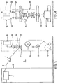
- Figs 3 and 4 also illustrate, end view. and front view, a working position of a machine according to the invention making it possible to produce self-twisted core wires.
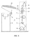
- Fig. 5 illustrates a variant making it possible to carry out an additional heat treatment of the material before the self-twisting operation.
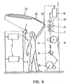
- Fig. 6 illustrates a variant making it possible to carry out a texturing treatment of the material.
- Fig. 7 illustrates another embodiment combining such a texturing process with the self-twisting operation.
- the machine according to the invention comprises a plurality of identical working positions arranged side by side on a support frame.
- the wire feeders 1 are separated from the wire processing means proper so as to form a passage area 3 for the operator.
- the wire 2 comes from coils stored on a conventional creel 5 disposed at the same level and spaced from the processing means.
- the creel 5 could be located on a platform so as to free up the space on the ground.
- the wire processing means are grouped on a common frame 6, shown in dotted lines on lafig. 1. These processing means are constituted from top to bottom by a self-twisting deliverer 7 making it possible to deliver two wires 2 in parallel.
- conventional means 8 are arranged below this deliverer 7 and communicate an alternating twist to the two treated wires 2.
- this deliverer 7 communicates an alternating twist to the two treated wires 2.
- a second deliverer 9 allows the self-twisted yarn produced to be called up, which is then returned conventionally at 10.
- a deliverer formed by a continuous shaft 11 extending over the entire width of the machine will be used, for example, on which rollers 12, 13 support the wires 2 individually.
- the means 8 making it possible to communicate an alternating twist to the wire consist, in the present case, of an assembly comprising a false twist member 14, formed for example of crossed belts simultaneously treating the two wires 2.
- the alternating twist is obtained by varying the length of the twist rise between the spindle 14 and the self-twisting deliverer 7, for example by means of a conventional intermittent deliverer 15.
- the two elementary wires 2 having received an alternating twist are assembled by simple self-twisting in downstream of spindle 14, their junction being obtained by means of a guide 16.
- the caller 9 for the formed wire can also consist of a continuous shaft 17, on which support individual conventional sleeves 18.
- the winding 10 is carried out in a conventional manner, for example by tangential drive. It is obvious that one could also carry out a winding by means of a pin with ring and cursor, if for example one wishes to twist the wire formed.
- Such an installation makes it possible to easily treat any type of yarn, whether it is based on continuous filaments or yarns of fibers.
- cold drawing can be carried out by adjusting the respective speeds of the feeder 1 and the self-twist 7.
- the two wires 2 which must be self-twisted are brought in parallel but nevertheless undergo a slight change of direction at the exit of the self-twisting deliverer 11, for example by means of guides 30, 31 making it possible to reduce their spacing, it could of course be envisaged to keep the spacing between these wires constant throughout the treatment, as shown in dashed lines in FIG. 2.
- the guides 30, 31 could possibly be deleted.
- the deliverer 1 could be arranged directly above and in the same vertical plane as the self-twisting deliverer 7 and that the means 8 making it possible to communicate the alternating torsion to the wires.
- Figs 3, 4, 5, 6 and 7 illustrate the adaptations which can be carried out in a simple manner on such a type of machine.
- Figs 3 and 4 show the adaptation of this machine for the production of self-twisted core wires.
- the frame 6 there is at the upper part of the frame 6 a supply 19 of wicks of fibers 20.
- the self-twisting deliverer 7 is constituted by the last pair of cylinders of a conventional stretching system such as for example a double sleeve system 21.
- the core wires are constituted by the wires 2 coming from the creel 5, these wires being incorporated in the wick 20 immediately upstream of the stretching deliverer 7, a condenser 22 can be provided in this area to facilitate the introduction of the core into the wick.
- guides 30, 31 may be provided at the outlet of the self-twisting deliverer 7 to reduce the spacing between the wires in the area where they are subjected to the operation allowing to give them an alternate twist. As before, it could be envisaged to keep the distance between the wires constant over the entire length of the treatment.
- Fig. 5 illustrates a variant in which a heat treatment member 23, such as an oven, is arranged in the upper part of the machine.
- This oven 23 which can be an open oven or a closed oven, is preferably arranged horizontally or slightly at an angle in the upper part of the machine.
- a complementary deliverer 24 shown in dotted lines in this FIG. 5 is provided at the outlet of the oven 23 and makes it possible to carry out a hot drawing, in cooperation with the feeder 1.
- This type of material can also be equipped with a wick feed system 20.
- the inclination of the oven 23 is such that the wire 2 is brought obliquely upstream of the last pair of rollers of the train. stretch forming the self-twisting deliverer 7.
- Fig. 6 illustrates a variant in which a false-twist texturing operation is carried out between the feeder 1 and the self-twister 7.
- this texturing operation can be combined with a simultaneous drawing of the wire 2.
- a plate cooling 25 can be provided between the spindle 26 and the furnace 23.
- the processing members are mounted symmetrically on a common frame.
- Fig. illustrates a variant of a machine in which the feeder 1, which in accordance with the invention is separated from the processing members, is arranged at a lower level so as to be able to adapt, between this delivering device and the processing members, a texturing installation, for example by false twisting, also comprising an oven 23, a cooling path 25 and a spindle 26.
- the passage zone 3 for the operator is located between the texturing zone and the treatment area to obtain the self-twisted yarn.
- a system for feeding a wick of fibers can be provided in the upper part of the machine.
- the machine includes breakage and stop detector means for each position, and can be equipped with any conventional means making it possible to correctly treat the wire, by example of voltage regulators, suction systems allowing correct launches to be made and / or eliminating the down that might escape during the treatment.
Landscapes
- Engineering & Computer Science (AREA)
- Mechanical Engineering (AREA)
- Textile Engineering (AREA)
- Yarns And Mechanical Finishing Of Yarns Or Ropes (AREA)
- Spinning Or Twisting Of Yarns (AREA)
Claims (11)
Applications Claiming Priority (2)
| Application Number | Priority Date | Filing Date | Title |
|---|---|---|---|
| FR7923871 | 1979-09-20 | ||
| FR7923871A FR2465805A1 (fr) | 1979-09-20 | 1979-09-20 | Machine pour l'obtention de fils autotordus |
Publications (2)
| Publication Number | Publication Date |
|---|---|
| EP0026149A1 EP0026149A1 (de) | 1981-04-01 |
| EP0026149B1 true EP0026149B1 (de) | 1983-11-23 |
Family
ID=9230000
Family Applications (1)
| Application Number | Title | Priority Date | Filing Date |
|---|---|---|---|
| EP80420104A Expired EP0026149B1 (de) | 1979-09-20 | 1980-09-17 | Maschine zur Herstellung selbstgezwirnter Garne |
Country Status (6)
| Country | Link |
|---|---|
| US (1) | US4364225A (de) |
| EP (1) | EP0026149B1 (de) |
| JP (1) | JPS5649027A (de) |
| AU (1) | AU6235080A (de) |
| DE (1) | DE3065695D1 (de) |
| FR (1) | FR2465805A1 (de) |
Families Citing this family (12)
| Publication number | Priority date | Publication date | Assignee | Title |
|---|---|---|---|---|
| FR2507634B1 (fr) * | 1981-06-12 | 1986-06-06 | Baulip Fil Sarl | Procede et appareil pour le filage de fils a ame |
| JPS60121302A (ja) * | 1983-11-30 | 1985-06-28 | Shoketsu Kinzoku Kogyo Co Ltd | アクチュエータの制御装置 |
| FR2583783A1 (fr) * | 1985-06-25 | 1986-12-26 | Asa Sa | Dispositif pour etirer, condenser et transporter une meche de fibres lors d'une operation de filature. |
| JPH0665884B2 (ja) * | 1990-08-31 | 1994-08-24 | エスエムシー株式会社 | アクチュエータの制御装置 |
| JPH0665885B2 (ja) * | 1990-08-31 | 1994-08-24 | エスエムシー株式会社 | アクチュエータの制御装置 |
| JPH03163201A (ja) * | 1990-08-31 | 1991-07-15 | Smc Corp | アクチュエータの制御方法および装置 |
| JPH04114287A (ja) * | 1990-09-05 | 1992-04-15 | Nec Off Syst Ltd | 演算器 |
| JPH03249403A (ja) * | 1990-11-30 | 1991-11-07 | Smc Corp | 弁機構 |
| JPH03249409A (ja) * | 1990-11-30 | 1991-11-07 | Smc Corp | ネットワーク制御装置 |
| JP4060508B2 (ja) * | 2000-02-16 | 2008-03-12 | Tmtマシナリー株式会社 | 延伸仮撚加工機 |
| FR2865220B1 (fr) * | 2004-01-16 | 2006-06-02 | Rieter Textile Machinery Fr | Unite de transformation de fils textiles |
| CH710527A1 (de) * | 2014-12-16 | 2016-06-30 | Rieter Ag Maschf | Spinnmaschine. |
Citations (5)
| Publication number | Priority date | Publication date | Assignee | Title |
|---|---|---|---|---|
| FR1405219A (fr) * | 1962-10-19 | 1965-07-09 | Commw Scient Ind Res Org | Procédé et dispositif pour former des fils torsadés |
| US4033102A (en) * | 1975-03-21 | 1977-07-05 | Centre Technique Industriel Dit: Institut Textile De France | Method and apparatus for twisting core strands |
| FR2381845A2 (fr) * | 1977-02-25 | 1978-09-22 | Asa Sa | Machine perfectionnee pour la fabrication de fils textures par fausse torsion |
| FR2410065A1 (fr) * | 1977-11-23 | 1979-06-22 | Zinser Textilmaschinen Gmbh | Machine d'etirage-texturation a fausse torsion |
| US4164839A (en) * | 1978-01-30 | 1979-08-21 | Akzona Incorporated | Yarn process |
Family Cites Families (7)
| Publication number | Priority date | Publication date | Assignee | Title |
|---|---|---|---|---|
| US3225533A (en) * | 1961-10-19 | 1965-12-28 | Commw Scient Ind Res Org | Apparatus and process for forming yarns and other twisted assemblies |
| US3468120A (en) * | 1968-07-30 | 1969-09-23 | Du Pont | Method of producing alternate twist yarn |
| AU8001475A (en) * | 1974-04-19 | 1976-10-14 | Commonwealth Scientific And Industrial Research Organization | Method of and apparatus for forming a multiply yarn |
| USRE30159E (en) | 1975-07-05 | 1979-11-27 | Barmag Barmer Maschinenfabrik Aktiengesellschaft | False twist-crimping machine |
| GB1537543A (en) * | 1976-03-23 | 1978-12-29 | Scragg & Sons | Yarn texturing machine |
| US4084400A (en) * | 1976-08-17 | 1978-04-18 | Pavel Mikhailovich Movshovich | Method of making self-twisted fibrous product from at least two strands |
| US4215642A (en) * | 1977-10-25 | 1980-08-05 | Wwg Industries Inc. | Variable twist self-twist yarn |
-
1979
- 1979-09-20 FR FR7923871A patent/FR2465805A1/fr active Granted
-
1980
- 1980-09-05 US US06/184,277 patent/US4364225A/en not_active Expired - Lifetime
- 1980-09-12 AU AU62350/80A patent/AU6235080A/en not_active Abandoned
- 1980-09-12 JP JP12703880A patent/JPS5649027A/ja active Pending
- 1980-09-17 EP EP80420104A patent/EP0026149B1/de not_active Expired
- 1980-09-17 DE DE8080420104T patent/DE3065695D1/de not_active Expired
Patent Citations (5)
| Publication number | Priority date | Publication date | Assignee | Title |
|---|---|---|---|---|
| FR1405219A (fr) * | 1962-10-19 | 1965-07-09 | Commw Scient Ind Res Org | Procédé et dispositif pour former des fils torsadés |
| US4033102A (en) * | 1975-03-21 | 1977-07-05 | Centre Technique Industriel Dit: Institut Textile De France | Method and apparatus for twisting core strands |
| FR2381845A2 (fr) * | 1977-02-25 | 1978-09-22 | Asa Sa | Machine perfectionnee pour la fabrication de fils textures par fausse torsion |
| FR2410065A1 (fr) * | 1977-11-23 | 1979-06-22 | Zinser Textilmaschinen Gmbh | Machine d'etirage-texturation a fausse torsion |
| US4164839A (en) * | 1978-01-30 | 1979-08-21 | Akzona Incorporated | Yarn process |
Also Published As
| Publication number | Publication date |
|---|---|
| FR2465805A1 (fr) | 1981-03-27 |
| FR2465805B1 (de) | 1982-10-01 |
| AU6235080A (en) | 1981-03-26 |
| DE3065695D1 (en) | 1983-12-29 |
| US4364225A (en) | 1982-12-21 |
| EP0026149A1 (de) | 1981-04-01 |
| JPS5649027A (en) | 1981-05-02 |
Similar Documents
| Publication | Publication Date | Title |
|---|---|---|
| EP0085634B1 (de) | Verfahren und Einrichtung zur Herstellung eines Garns | |
| EP0022421B1 (de) | Verfahren und Vorrichtung zum Herstellen eines Zwirnes mit über seine Länge abwechselnder S- und Z-Drehung | |
| EP0085635B1 (de) | Verfahren und Vorrichtung zum Herstellen von Coregarn | |
| EP0026149A1 (de) | Maschine zur Herstellung selbstgezwirnter Garne | |
| EP0882146B1 (de) | Vorrichtung zur herstellung eines mischgarnes durch zusammenkuppeln von zwei falschdralltexturierten garnen | |
| FR2690694A1 (fr) | Procédé pour le traitement de fils chimiques, notamment lors d'une opération de texturation, et installation textile mettant en Óoeuvre ce procédé. | |
| US6076345A (en) | Method and apparatus for generating a yarn composed of at least two yarn components | |
| FR2560230A1 (fr) | Procede pour l'obtention d'un file de fibres | |
| EP0815303B1 (de) | Maschine zum kontinuierlichen zwirnen oder kablieren von fäden und anschliessend ergänzender wärmebehandlung | |
| GB1187532A (en) | Yarn Texturing apparatus and method | |
| EP0098230B1 (de) | Verfahren und Vorrichtung zum Herstellen von Coregarn aus Fasern | |
| EP0206956A2 (de) | Spinnvorrichtung zur Herstellung von überzogenen Garnen | |
| EP0939153B1 (de) | Vorrichtung zum Falschdrall-Spinnen | |
| FR2736937A1 (fr) | Machine d'etirage-texturation par fausse torsion | |
| EP0155892A1 (de) | Verfahren zur Herstellung von Spinngarn | |
| FR2667618A1 (fr) | Procede pour l'obtention d'un file de fibres et dispositif pour sa mise en óoeuvre. | |
| EP0533596B1 (de) | Verbesserte Vorrichtung zum kontinuierlichen Drallen und eine zusätzliche Texturierbehandlung eines synthetischen Garnes | |
| FR2520391A1 (en) | Prodn. of fibres-coated, multifilament thread for weaving etc. - contacts thread with fibres in circumferential channel of rotating guide wheel | |
| CH572113A5 (en) | Spirally sheathed yarn of stable fibres without twist - core not fully covered, enclosed by uniformly spaced spirals(BR-23.12.75) | |
| FR2560228A1 (fr) | Dispositif pour l'obtention d'un file de fibres | |
| FR2533236A1 (fr) | Procede et dispositif pour l'obtention d'un file de fibres comportant une ame interne et nouveaux types de files ainsi realises | |
| FR2533593A1 (fr) | Produit textile type file de fibres, procede et dispositif pour sa fabrication | |
| FR2490686A1 (fr) | Machine pour la texturation de fils par fausse torsion | |
| EP0137088A1 (de) | Verfahren und Vorrichtung zur Garntexturierung, insbesondere durch Falschdrehen | |
| BE660308A (de) |
Legal Events
| Date | Code | Title | Description |
|---|---|---|---|
| PUAI | Public reference made under article 153(3) epc to a published international application that has entered the european phase |
Free format text: ORIGINAL CODE: 0009012 |
|
| AK | Designated contracting states |
Designated state(s): CH DE GB IT |
|
| 17P | Request for examination filed |
Effective date: 19810521 |
|
| GRAA | (expected) grant |
Free format text: ORIGINAL CODE: 0009210 |
|
| AK | Designated contracting states |
Designated state(s): CH DE GB IT LI |
|
| PG25 | Lapsed in a contracting state [announced via postgrant information from national office to epo] |
Ref country code: IT Free format text: LAPSE BECAUSE OF FAILURE TO SUBMIT A TRANSLATION OF THE DESCRIPTION OR TO PAY THE FEE WITHIN THE PRESCRIBED TIME-LIMIT;WARNING: LAPSES OF ITALIAN PATENTS WITH EFFECTIVE DATE BEFORE 2007 MAY HAVE OCCURRED AT ANY TIME BEFORE 2007. THE CORRECT EFFECTIVE DATE MAY BE DIFFERENT FROM THE ONE RECORDED. Effective date: 19831123 |
|
| REF | Corresponds to: |
Ref document number: 3065695 Country of ref document: DE Date of ref document: 19831229 |
|
| PGFP | Annual fee paid to national office [announced via postgrant information from national office to epo] |
Ref country code: CH Payment date: 19840815 Year of fee payment: 5 |
|
| PGFP | Annual fee paid to national office [announced via postgrant information from national office to epo] |
Ref country code: DE Payment date: 19840818 Year of fee payment: 5 |
|
| PLBE | No opposition filed within time limit |
Free format text: ORIGINAL CODE: 0009261 |
|
| STAA | Information on the status of an ep patent application or granted ep patent |
Free format text: STATUS: NO OPPOSITION FILED WITHIN TIME LIMIT |
|
| 26N | No opposition filed | ||
| PG25 | Lapsed in a contracting state [announced via postgrant information from national office to epo] |
Ref country code: LI Effective date: 19860930 Ref country code: CH Effective date: 19860930 |
|
| REG | Reference to a national code |
Ref country code: CH Ref legal event code: PL |
|
| PG25 | Lapsed in a contracting state [announced via postgrant information from national office to epo] |
Ref country code: DE Effective date: 19870602 |
|
| GBPC | Gb: european patent ceased through non-payment of renewal fee | ||
| PG25 | Lapsed in a contracting state [announced via postgrant information from national office to epo] |
Ref country code: GB Effective date: 19881118 |