EP0026324A1 - Appareil électromédical à courant de stimulation - Google Patents
Appareil électromédical à courant de stimulation Download PDFInfo
- Publication number
- EP0026324A1 EP0026324A1 EP80105041A EP80105041A EP0026324A1 EP 0026324 A1 EP0026324 A1 EP 0026324A1 EP 80105041 A EP80105041 A EP 80105041A EP 80105041 A EP80105041 A EP 80105041A EP 0026324 A1 EP0026324 A1 EP 0026324A1
- Authority
- EP
- European Patent Office
- Prior art keywords
- patient
- current
- transistor
- operating voltage
- voltage
- Prior art date
- Legal status (The legal status is an assumption and is not a legal conclusion. Google has not performed a legal analysis and makes no representation as to the accuracy of the status listed.)
- Granted
Links
- 230000000638 stimulation Effects 0.000 claims abstract description 14
- 230000001681 protective effect Effects 0.000 claims abstract description 13
- 239000003990 capacitor Substances 0.000 claims description 4
- 238000011144 upstream manufacturing Methods 0.000 claims 1
- 230000000903 blocking effect Effects 0.000 description 2
- 230000004913 activation Effects 0.000 description 1
- 238000010586 diagram Methods 0.000 description 1
- 230000000694 effects Effects 0.000 description 1
- 230000007794 irritation Effects 0.000 description 1
- 230000007257 malfunction Effects 0.000 description 1
- 230000010363 phase shift Effects 0.000 description 1
- 238000002560 therapeutic procedure Methods 0.000 description 1
Images
Classifications
-
- H—ELECTRICITY
- H02—GENERATION; CONVERSION OR DISTRIBUTION OF ELECTRIC POWER
- H02H—EMERGENCY PROTECTIVE CIRCUIT ARRANGEMENTS
- H02H3/00—Emergency protective circuit arrangements for automatic disconnection directly responsive to an undesired change from normal electric working condition with or without subsequent reconnection ; integrated protection
- H02H3/08—Emergency protective circuit arrangements for automatic disconnection directly responsive to an undesired change from normal electric working condition with or without subsequent reconnection ; integrated protection responsive to excess current
- H02H3/10—Emergency protective circuit arrangements for automatic disconnection directly responsive to an undesired change from normal electric working condition with or without subsequent reconnection ; integrated protection responsive to excess current additionally responsive to some other abnormal electrical conditions
-
- Y—GENERAL TAGGING OF NEW TECHNOLOGICAL DEVELOPMENTS; GENERAL TAGGING OF CROSS-SECTIONAL TECHNOLOGIES SPANNING OVER SEVERAL SECTIONS OF THE IPC; TECHNICAL SUBJECTS COVERED BY FORMER USPC CROSS-REFERENCE ART COLLECTIONS [XRACs] AND DIGESTS
- Y10—TECHNICAL SUBJECTS COVERED BY FORMER USPC
- Y10S—TECHNICAL SUBJECTS COVERED BY FORMER USPC CROSS-REFERENCE ART COLLECTIONS [XRACs] AND DIGESTS
- Y10S128/00—Surgery
- Y10S128/908—Patient protection from electric shock
Definitions
- the invention relates to an electromedical device, in particular a stimulation current device, with an output stage as a current shape generator for current-constant stimulation current and a protective device assigned to the output stage, which switches off the patient output from the operating voltage when a predeterminable maximum value of the patient current is exceeded.
- Known stimulation current devices have output stages for current-constant patient current, which operate with a relatively high operating voltage (up to a few 100 volts). This is to ensure that even with extremely high patient resistances, the currents required for therapy or diagnostics can still be applied with a correspondingly high operating voltage requirement.
- an stimulation current device is also known, in which the protective device is specially designed so that the operating voltage regulator of the device is reduced accordingly in the event of increases in the patient current caused by rapid changes in resistance.
- This protective device offers protection in particular for such an accident in which the current supply electrodes detach from the application site, the current transfer area being reduced, so that the current density on the skin at the application site takes on very high values and can therefore lead to unpleasant irritations.
- This protective device also works against rapid changes in intensity on the intensity setting element. In contrast, this known circuit does not intervene if the actually flowing patient current or the like due to device errors. takes too high a value.
- stimulation current devices of the prior art have, in the patient circuit as a protective device, for example so-called quick-acting fuses which are destroyed by correspondingly high currents and thus interrupt the current flow. Such fuses are known to be imprecise and also unsafe. Electromagnetic switching devices (relays) do not make any fundamental improvements here either. Although they switch faster (in the millisecond range), they can only provide protection against a given overcurrent.
- the object of the invention is therefore to provide an improved protective device for electromedical devices.
- a safety circuit for switching off the patient output from the operating voltage also responds as a protective device if the patient current deviates from the value set on an intensity setting element, for which purpose the output stage is connected to the safety circuit.
- the safety circuit preferably contains a bistable switching stage, for example composed of two transistors in a push-pull circuit, which switches the patient output on to the operating voltage in one state and switches off the operating voltage in the other state.
- the switching stage is not only controlled by an overcurrent signal, but also by a signal obtained by comparing the setpoint value of the patient current with the actually flowing current.
- the deviation of the patient flow from the preselected setpoint also causes the safety device to be switched off.
- Such a deviation which can also be an undercurrent, is an indication of a device fault, so that the operating voltage is interrupted even if the maximum patient current for switching off has not yet been reached.
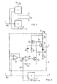
- 1 means the connection of the control voltage of an electrical stimulation device and 2 the connection to an operating voltage source.
- the operating voltage U B is, for example, +200 V.
- a control voltage proportional to the desired patient current is fed in from an intensity setting element (not shown) via control input 1.
- Patient flows of any curve shape can be preselected.
- a safety circuit 3 is now switched on, on the one hand, as a protective device and, on the other hand, an output stage 5 as a current waveform generator.
- Corresponding currents are generated from the control voltages by the output stage 5; the Power stage 5 is connected to ground potential via a defined resistor 6.
- the current flowing through the resistor 6 corresponds to the patient current IPat.
- Fig. 1 it can be seen that the device is designed such that the safety circuit is on the one hand in the operating voltage-carrying branch, but on the other hand it is also controlled by the output stage as an output stage for the preselected patient current.
- the detailed function of this safety circuit according to the invention can be seen in detail in FIG. 2.
- a first transistor 31 is arranged in an emitter circuit, the collector path of which is located at output 4.
- a second transistor 32 is connected in parallel in an emitter circuit, the voltage drop across a resistor 33 in the emitter path of the first transistor 31 being connected to the base of the second transistor 32 as a control signal via a resistor 34.
- the second transistor 32 is in turn connected on the collector side as a control line to the base of the first transistor 31.
- a bistable multivibrator is therefore formed by the transistors 31, 32 in push-pull circuit.
- This flip-flop switches the patient output in the one state to the operating voltage U B and in the other state of the operating voltage U B from the fourth
- the control signal for the switching stage formed in this way is derived on the one hand from the value of the patient current itself and on the other hand from a comparison value of the set patient current with the actually flowing current.
- the second transistor 32 has an RC element with a resistor 35 and a capacitor 38 connected in parallel on the collector side, while the collector side of the first transistor 31 is connected via a blocking diode and a voltage divider with resistors 36 and 37 is fed back to the emitter path of the first transistor.
- the control line for the second transistor 32 is connected to the output of a comparator 41 via a third switching transistor 40.
- the control voltage U St set on the intensity setting element and, on the other hand, a voltage corresponding to the actually flowing patient current I Pat are given to the inputs of the comparator 41.
- the control voltage is connected from control input 1 via a feedback operational amplifier 42 to the inverting input of comparator 41 with a low resistance.
- the voltage drop across the defined resistor 6, which is proportional to the patient current, is connected to the other input. Via a voltage divider with resistors 43 and 44, this voltage is reduced by a predeterminable value, for example 20%.
- Both input lines of the comparator 41 are coupled via a capacitor 45.
- control voltage is initially coupled through the capacitor 45 to the second line. This has the effect that the actually existing current intensities are actually compared at the comparator 41 and an output signal is not only generated due to phase shifts in the case of changing current forms.
- the first transistor 31 When the stimulation current device is operated with the safety circuit described, the first transistor 31 is normally conductive, so that the operating voltage is above the emitter-collector path at the patient output 4. The preselected current is generated via the output stage 5 and connected to the other patient exit 7. If the current now rises above the safety-related limit value of 80 mA, the voltage drop across the resistor 33 increases accordingly. If this voltage drop is greater than the base-emitter voltage of the transistor 32, the transistor 32 switches to the conductive state, whereby from the collector path the base of the first transistor 31 is driven. This blocks transistor 31; the fuse has blown.
- the bistable switching stage formed by the transistors and the first transistor 31 are turned over very quickly. Values ⁇ 10 ⁇ s are achieved.
- the blocking of transistor 31 is maintained as long as the operating voltage U B is present.
- the collector path of the transistor 32 is discharged via the RC element 35, 38.
- the switching stage is then always in the state in which the first transistor 31 is turned on, ie the fuse is conductive.
- the comparator 41 With the comparator 41, the voltage drop across the resistor 6, which is reduced by a preselected amount, is constantly compared with the control voltage U st during the operation of the electromedical device. Thus, if the patient current exceeds the value preselected on the intensity setting element, for example by 20%, the comparator 41 tilts and the output signal of the comparator 41 is added to the control signal for the second transistor 32. In this way, the second transistor 32 is also switched through and consequently the first transistor 31 is again blocked.
- an operational amplifier as a comparator 41 is specifically connected such that only patient current values that are greater than the selected target value lead to the additional activation of the safety circuit.
- the fuse formed by the circuit described therefore also operates in any case if the patient current is still below the permissible maximum current, but deviates from the value preselected on the intensity setting element. This creates a particularly effective protection of the patient against disturbances of the stimulation current device.
Landscapes
- Electrotherapy Devices (AREA)
Priority Applications (1)
| Application Number | Priority Date | Filing Date | Title |
|---|---|---|---|
| AT80105041T ATE3753T1 (de) | 1979-08-31 | 1980-08-25 | Elektromedizinisches reizstromgeraet. |
Applications Claiming Priority (2)
| Application Number | Priority Date | Filing Date | Title |
|---|---|---|---|
| DE2935309A DE2935309C2 (de) | 1979-08-31 | 1979-08-31 | Elektromedizinisches Gerät. |
| DE2935309 | 1979-08-31 |
Publications (3)
| Publication Number | Publication Date |
|---|---|
| EP0026324A1 true EP0026324A1 (fr) | 1981-04-08 |
| EP0026324B1 EP0026324B1 (fr) | 1983-06-15 |
| EP0026324B2 EP0026324B2 (fr) | 1986-07-02 |
Family
ID=6079777
Family Applications (1)
| Application Number | Title | Priority Date | Filing Date |
|---|---|---|---|
| EP80105041A Expired EP0026324B2 (fr) | 1979-08-31 | 1980-08-25 | Appareil électromédical à courant de stimulation |
Country Status (4)
| Country | Link |
|---|---|
| US (1) | US4363324A (fr) |
| EP (1) | EP0026324B2 (fr) |
| AT (1) | ATE3753T1 (fr) |
| DE (1) | DE2935309C2 (fr) |
Cited By (11)
| Publication number | Priority date | Publication date | Assignee | Title |
|---|---|---|---|---|
| EP0054654A1 (fr) * | 1980-12-18 | 1982-06-30 | Siemens Aktiengesellschaft | Appareil électro-médical |
| FR2507900A1 (fr) * | 1981-06-17 | 1982-12-24 | Faiveley Sa | Dispositif de securite pour appareil electrologique et procede s'y rapportant |
| EP0087617A1 (fr) * | 1982-02-26 | 1983-09-07 | Siemens Aktiengesellschaft | Appareil médical de thérapie physique, en particulier appareil de stimulation électro-médical |
| GB2135840A (en) * | 1983-02-28 | 1984-09-05 | Westinghouse Electric Corp | Electronic circuit breaker |
| EP0170365A3 (fr) * | 1984-06-05 | 1986-02-26 | CODMAN & SHURTLEFF INC. | Dispositif pour la stimulation transcutanée des nerfs avec surveillance |
| EP0335266A1 (fr) * | 1988-03-31 | 1989-10-04 | HENNEBERG & BRUNNER | Appareil de stimulation |
| EP0367338A1 (fr) * | 1988-10-31 | 1990-05-09 | Ingenieursburo Uniphy B.V. | Appareil d'électrothérapie |
| EP0569616A1 (fr) * | 1992-05-12 | 1993-11-18 | Pacesetter AB | Appareil pour la délivrance de impulsions électriques à un tissu vivant |
| US5350403A (en) * | 1992-06-17 | 1994-09-27 | Siemens Aktiengesellschaft | Apparatus for charging living tissue with electrical pulses |
| EP0854741A4 (fr) * | 1994-12-13 | 2000-05-03 | Conrad M Swartz | Circuit de controle de securite d'un dispositif a electrochoc |
| WO2014139486A1 (fr) * | 2013-03-09 | 2014-09-18 | Kares Jiri | Dispositif de régulation empêchant les chocs électriques dans les dispositifs utilisant l'électrothérapie en vue d'un traitement et procédé de prévention contre les chocs électriques |
Families Citing this family (40)
| Publication number | Priority date | Publication date | Assignee | Title |
|---|---|---|---|---|
| DE3127231C2 (de) * | 1981-07-10 | 1983-10-27 | COSMODERM Medizinische und kosmetische Geräte GmbH, 7512 Rheinstetten | Gerät zur galvanischen Reizstrombehandlung |
| DE3216911A1 (de) * | 1982-05-06 | 1983-11-10 | Datron-Electronic Pichl & Schulte KG, 6109 Mühltal | Heimgeraet zur elektrotherapeutischen behandlung |
| DE3232517A1 (de) * | 1982-09-01 | 1984-03-01 | Siemens AG, 1000 Berlin und 8000 München | Elektromedizinisches geraet |
| DE3346673A1 (de) * | 1983-12-23 | 1984-05-03 | Wolfgang 8201 Neubeuern Preywisch | Reizstromtherapiegeraet fuer die medizinisch therapeutische und/oder diagnostische anwendung |
| US4686991A (en) * | 1985-06-17 | 1987-08-18 | Minnesota Mining And Manufacturing Company | Electrical stimulator for biological tissue utilizing linear current output circuit |
| US4722343A (en) * | 1985-12-16 | 1988-02-02 | Nicolet Instrument Corporation | Method and apparatus for applying electrical stimulus pulses to a subject |
| US5376103A (en) * | 1992-03-19 | 1994-12-27 | Angeion Corporation | Electrode system for implantable defibrillator |
| FR2728799B1 (fr) * | 1994-12-30 | 1997-03-28 | Ela Medical Sa | Dispositif implantable actif, notamment stimulateur ou defibrillateur cardiaque, comportant des moyens de protection contre les perturbations electromagnetiques d'origine externe |
| US7270661B2 (en) | 1995-11-22 | 2007-09-18 | Arthocare Corporation | Electrosurgical apparatus and methods for treatment and removal of tissue |
| CA2190901A1 (fr) * | 1995-11-24 | 1997-05-25 | John B. Shaw | Systeme pour electrochocs avec dispositifs de securite ameliores |
| US6505079B1 (en) * | 2000-09-13 | 2003-01-07 | Foster Bio Technology Corp. | Electrical stimulation of tissue for therapeutic and diagnostic purposes |
| US6650936B2 (en) | 2001-04-23 | 2003-11-18 | Medtronic Physio-Control Manufacturing Corporation. | Method and apparatus for delivering electrotherapy having an equivalent probability of success for different patients |
| US6892086B2 (en) | 2001-07-11 | 2005-05-10 | Michael J. Russell | Medical electrode for preventing the passage of harmful current to a patient |
| US7499746B2 (en) | 2004-01-30 | 2009-03-03 | Encore Medical Asset Corporation | Automated adaptive muscle stimulation method and apparatus |
| US8140165B2 (en) | 2005-01-28 | 2012-03-20 | Encore Medical Asset Corporation | Independent protection system for an electrical muscle stimulation apparatus and method of using same |
| WO2006113801A2 (fr) | 2005-04-19 | 2006-10-26 | Compex Technologies, Inc. | Dispositif de stimulation electrique et procede pour le traitement therapeutique et le soulagement de la douleur |
| US7632267B2 (en) * | 2005-07-06 | 2009-12-15 | Arthrocare Corporation | Fuse-electrode electrosurgical apparatus |
| US7691101B2 (en) | 2006-01-06 | 2010-04-06 | Arthrocare Corporation | Electrosurgical method and system for treating foot ulcer |
| US8876746B2 (en) | 2006-01-06 | 2014-11-04 | Arthrocare Corporation | Electrosurgical system and method for treating chronic wound tissue |
| WO2007143445A2 (fr) | 2006-05-30 | 2007-12-13 | Arthrocare Corporation | Système d'ablation de tissus durs |
| GB2452103B (en) | 2007-01-05 | 2011-08-31 | Arthrocare Corp | Electrosurgical system with suction control apparatus and system |
| US8620438B1 (en) | 2007-02-13 | 2013-12-31 | Encore Medical Asset Corporation | Method and apparatus for applying neuromuscular electrical stimulation |
| US7862560B2 (en) | 2007-03-23 | 2011-01-04 | Arthrocare Corporation | Ablation apparatus having reduced nerve stimulation and related methods |
| EP2011433A1 (fr) * | 2007-07-05 | 2009-01-07 | INTERUNIVERSITAIR MICROELEKTRONICA CENTRUM vzw (IMEC) | Système sans fil autonome pour des mesures de potentiel évoquées |
| US9358063B2 (en) | 2008-02-14 | 2016-06-07 | Arthrocare Corporation | Ablation performance indicator for electrosurgical devices |
| US8574187B2 (en) | 2009-03-09 | 2013-11-05 | Arthrocare Corporation | System and method of an electrosurgical controller with output RF energy control |
| US8257350B2 (en) | 2009-06-17 | 2012-09-04 | Arthrocare Corporation | Method and system of an electrosurgical controller with wave-shaping |
| AU2010306068B2 (en) * | 2009-10-12 | 2016-03-10 | Newsouth Innovations Pty Limited | Method of power and data transfer in implantable electronic devices |
| US8372067B2 (en) | 2009-12-09 | 2013-02-12 | Arthrocare Corporation | Electrosurgery irrigation primer systems and methods |
| US8747399B2 (en) | 2010-04-06 | 2014-06-10 | Arthrocare Corporation | Method and system of reduction of low frequency muscle stimulation during electrosurgical procedures |
| US8685018B2 (en) | 2010-10-15 | 2014-04-01 | Arthrocare Corporation | Electrosurgical wand and related method and system |
| USD658760S1 (en) | 2010-10-15 | 2012-05-01 | Arthrocare Corporation | Wound care electrosurgical wand |
| US9079032B2 (en) | 2010-11-10 | 2015-07-14 | Cardiac Pacemakers, Inc. | Power supply management for implantable neurostimulation devices |
| US8792992B2 (en) * | 2010-11-10 | 2014-07-29 | Cardiac Pacemakers, Inc. | Low-power system and methods for neuromodulation |
| US9131597B2 (en) | 2011-02-02 | 2015-09-08 | Arthrocare Corporation | Electrosurgical system and method for treating hard body tissue |
| US8731657B1 (en) * | 2011-07-05 | 2014-05-20 | TAMA Research Corp. | Multi-mode microcurrent stimulus system with safety circuitry and related methods |
| US9693818B2 (en) | 2013-03-07 | 2017-07-04 | Arthrocare Corporation | Methods and systems related to electrosurgical wands |
| US9713489B2 (en) | 2013-03-07 | 2017-07-25 | Arthrocare Corporation | Electrosurgical methods and systems |
| US9801678B2 (en) | 2013-03-13 | 2017-10-31 | Arthrocare Corporation | Method and system of controlling conductive fluid flow during an electrosurgical procedure |
| EP3500335A4 (fr) * | 2016-08-17 | 2020-06-10 | Tam, Pui Ling | Dispositif non invasif et procédé de stimulation de tissus vulvaires et de muscles du plancher pelvien pour traiter et améliorer un dysfonctionnement ou des troubles et unité de sonde utilisée à cet effet |
Citations (11)
| Publication number | Priority date | Publication date | Assignee | Title |
|---|---|---|---|---|
| DD112037A1 (fr) * | 1974-07-08 | 1975-03-12 | ||
| DE2558525A1 (de) * | 1975-02-10 | 1976-08-19 | Sybron Corp | Schaltung zur abgabe eines gleichstromes geringer intensitaet |
| US4021703A (en) * | 1975-06-02 | 1977-05-03 | Westinghouse Electric Corporation | Phase imbalance detection circuit |
| FR2332034A1 (fr) * | 1975-11-24 | 1977-06-17 | Stimulation Tech | Circuit protecteur pour stimulateur medical |
| DE2721757A1 (de) * | 1976-05-19 | 1977-11-24 | Nippon Coinco Co Ltd | Medizinisches niederfrequenz-behandlungsgeraet |
| DE2658096A1 (de) * | 1976-05-19 | 1977-12-08 | Herwig Dipl Ing Dr Thoma | Elektromedizinischer reizstromapparat zur anwendung hoher stroeme |
| DD129400A1 (de) * | 1977-02-17 | 1978-01-18 | Beate Neudert | Schutzschaltung fuer ein elektromedizinisches reizstromgeraet |
| DD135265A1 (de) * | 1974-07-08 | 1979-04-18 | Roland Moeckel | Ueberstromschutzschaltung fuer elektronisch stabilisierte spannungsquellen |
| DE2749792A1 (de) * | 1977-11-07 | 1979-05-10 | Siemens Ag | Elektromedizinisches geraet |
| FR2420980A1 (fr) * | 1978-03-30 | 1979-10-26 | Winkler U | Dispositif a commande automatique servant a eviter les douleurs a l'accouchement |
| US4175255A (en) * | 1977-09-06 | 1979-11-20 | Branderud Nils P | Device to protect against flow of current |
Family Cites Families (7)
| Publication number | Priority date | Publication date | Assignee | Title |
|---|---|---|---|---|
| DE1206958B (de) * | 1964-11-28 | 1965-12-16 | Philips Patentverwaltung | Bistabile Kippschaltung mit einstellbarer Verzoegerung des Umschaltvorganges |
| US3321645A (en) * | 1965-02-25 | 1967-05-23 | James E Webb | Switching circuit employing regeneratively connected complementary transistors |
| US3587563A (en) * | 1969-01-08 | 1971-06-28 | Us Army | Heartbeat monitor |
| US3709212A (en) * | 1970-08-05 | 1973-01-09 | Gould Inc | Multichannel electrocardiograph having one less input amplifiers than the number of signals to be measured |
| DE2340123A1 (de) * | 1973-08-08 | 1975-02-20 | Schwarzer Gmbh Fritz | Ueberstrom-schutzschaltung |
| GB1480736A (en) * | 1973-08-23 | 1977-07-20 | Matburn Ltd | Electrodiathermy apparatus |
| US4088141A (en) * | 1976-04-27 | 1978-05-09 | Stimulation Technology, Inc. | Fault circuit for stimulator |
-
1979
- 1979-08-31 DE DE2935309A patent/DE2935309C2/de not_active Expired
-
1980
- 1980-08-25 AT AT80105041T patent/ATE3753T1/de not_active IP Right Cessation
- 1980-08-25 US US06/181,097 patent/US4363324A/en not_active Expired - Lifetime
- 1980-08-25 EP EP80105041A patent/EP0026324B2/fr not_active Expired
Patent Citations (11)
| Publication number | Priority date | Publication date | Assignee | Title |
|---|---|---|---|---|
| DD112037A1 (fr) * | 1974-07-08 | 1975-03-12 | ||
| DD135265A1 (de) * | 1974-07-08 | 1979-04-18 | Roland Moeckel | Ueberstromschutzschaltung fuer elektronisch stabilisierte spannungsquellen |
| DE2558525A1 (de) * | 1975-02-10 | 1976-08-19 | Sybron Corp | Schaltung zur abgabe eines gleichstromes geringer intensitaet |
| US4021703A (en) * | 1975-06-02 | 1977-05-03 | Westinghouse Electric Corporation | Phase imbalance detection circuit |
| FR2332034A1 (fr) * | 1975-11-24 | 1977-06-17 | Stimulation Tech | Circuit protecteur pour stimulateur medical |
| DE2721757A1 (de) * | 1976-05-19 | 1977-11-24 | Nippon Coinco Co Ltd | Medizinisches niederfrequenz-behandlungsgeraet |
| DE2658096A1 (de) * | 1976-05-19 | 1977-12-08 | Herwig Dipl Ing Dr Thoma | Elektromedizinischer reizstromapparat zur anwendung hoher stroeme |
| DD129400A1 (de) * | 1977-02-17 | 1978-01-18 | Beate Neudert | Schutzschaltung fuer ein elektromedizinisches reizstromgeraet |
| US4175255A (en) * | 1977-09-06 | 1979-11-20 | Branderud Nils P | Device to protect against flow of current |
| DE2749792A1 (de) * | 1977-11-07 | 1979-05-10 | Siemens Ag | Elektromedizinisches geraet |
| FR2420980A1 (fr) * | 1978-03-30 | 1979-10-26 | Winkler U | Dispositif a commande automatique servant a eviter les douleurs a l'accouchement |
Cited By (12)
| Publication number | Priority date | Publication date | Assignee | Title |
|---|---|---|---|---|
| EP0054654A1 (fr) * | 1980-12-18 | 1982-06-30 | Siemens Aktiengesellschaft | Appareil électro-médical |
| FR2507900A1 (fr) * | 1981-06-17 | 1982-12-24 | Faiveley Sa | Dispositif de securite pour appareil electrologique et procede s'y rapportant |
| EP0087617A1 (fr) * | 1982-02-26 | 1983-09-07 | Siemens Aktiengesellschaft | Appareil médical de thérapie physique, en particulier appareil de stimulation électro-médical |
| GB2135840A (en) * | 1983-02-28 | 1984-09-05 | Westinghouse Electric Corp | Electronic circuit breaker |
| EP0170365A3 (fr) * | 1984-06-05 | 1986-02-26 | CODMAN & SHURTLEFF INC. | Dispositif pour la stimulation transcutanée des nerfs avec surveillance |
| EP0335266A1 (fr) * | 1988-03-31 | 1989-10-04 | HENNEBERG & BRUNNER | Appareil de stimulation |
| EP0367338A1 (fr) * | 1988-10-31 | 1990-05-09 | Ingenieursburo Uniphy B.V. | Appareil d'électrothérapie |
| EP0569616A1 (fr) * | 1992-05-12 | 1993-11-18 | Pacesetter AB | Appareil pour la délivrance de impulsions électriques à un tissu vivant |
| US5350403A (en) * | 1992-06-17 | 1994-09-27 | Siemens Aktiengesellschaft | Apparatus for charging living tissue with electrical pulses |
| EP0854741A4 (fr) * | 1994-12-13 | 2000-05-03 | Conrad M Swartz | Circuit de controle de securite d'un dispositif a electrochoc |
| WO2014139486A1 (fr) * | 2013-03-09 | 2014-09-18 | Kares Jiri | Dispositif de régulation empêchant les chocs électriques dans les dispositifs utilisant l'électrothérapie en vue d'un traitement et procédé de prévention contre les chocs électriques |
| GB2530421A (en) * | 2013-03-09 | 2016-03-23 | Jiri Kares | Regulation device preventing electrical shock in devices using electrotherapy for treatment and the method of prevention of electric shock |
Also Published As
| Publication number | Publication date |
|---|---|
| US4363324A (en) | 1982-12-14 |
| EP0026324B2 (fr) | 1986-07-02 |
| EP0026324B1 (fr) | 1983-06-15 |
| DE2935309C2 (de) | 1981-11-26 |
| DE2935309A1 (de) | 1981-03-12 |
| ATE3753T1 (de) | 1983-06-15 |
Similar Documents
| Publication | Publication Date | Title |
|---|---|---|
| EP0026324B1 (fr) | Appareil électromédical à courant de stimulation | |
| DE60017203T2 (de) | Laststeuersystem zum Zuführen eines Stroms von einer AC-Quelle zu einer Last | |
| DE2439587A1 (de) | Elektrochirurgische vorrichtung | |
| DE102006054354B4 (de) | Selbstschützende Crowbar | |
| DE2614491C3 (de) | Schaltungsanordnung zum Überwachen der Funktionsbereitschaft der Auslöseorgane einer Sicherheitseinrichtung für Fahrzeuge | |
| DE112013007534T5 (de) | Schutzschaltung für eine Robotersteuerung | |
| EP0072523A2 (fr) | Circuit de protection pour un transistor à effet de champ dans un circuit de charge | |
| DE102013219173B4 (de) | Spannungsversorgung für elektrische Fokussierung von Elektronenstrahlen | |
| EP0001806B1 (fr) | Appareil d'excitation électromédical | |
| EP0698794A1 (fr) | Circuit de détection de tension trop basse | |
| EP0098460B1 (fr) | Dispositif de régulation pour organe électrique de manoeuvre | |
| EP0203419B1 (fr) | Alimentation de puissance à découpage sur le circuit primaire | |
| DE68908342T2 (de) | Elektrotherapie-Gerät. | |
| DE3240280C2 (fr) | ||
| DE3047861A1 (de) | Elektromedizinisches geraet | |
| DE3519791C2 (fr) | ||
| DE2100929A1 (de) | Steuerschaltung zur Versorgung eines induktiven Verbrauchers | |
| DE1119986B (de) | UEberwachungseinrichtung fuer elektronische Anlagen | |
| DE2009039A1 (de) | Schaltung mit Überstromschutz | |
| DE2544482C3 (de) | Aus einer Strom- und Spannungsbegrenzungsschaltung bestehende Zenerbarriere | |
| DE3424040C2 (fr) | ||
| DE2454196B2 (de) | Brandmelder | |
| DE3246944A1 (de) | Schaltungsanordnung zur ueberwachung einer elektrischen spannung | |
| DE1925688C3 (de) | Einrichtung zur gleichmäßigen Strombelastung von parallelgeschalteten Gleichrichtern | |
| EP0303939A1 (fr) | Dispositif à courant de stimulation fonctionnant à tension constante |
Legal Events
| Date | Code | Title | Description |
|---|---|---|---|
| PUAI | Public reference made under article 153(3) epc to a published international application that has entered the european phase |
Free format text: ORIGINAL CODE: 0009012 |
|
| AK | Designated contracting states |
Designated state(s): AT BE CH FR GB IT NL SE |
|
| 17P | Request for examination filed |
Effective date: 19811002 |
|
| ITF | It: translation for a ep patent filed | ||
| GRAA | (expected) grant |
Free format text: ORIGINAL CODE: 0009210 |
|
| AK | Designated contracting states |
Designated state(s): AT BE CH FR GB IT LI NL SE |
|
| REF | Corresponds to: |
Ref document number: 3753 Country of ref document: AT Date of ref document: 19830615 Kind code of ref document: T |
|
| ET | Fr: translation filed | ||
| PLBI | Opposition filed |
Free format text: ORIGINAL CODE: 0009260 |
|
| 26 | Opposition filed |
Opponent name: ROBERT BOSCH GMBH Effective date: 19840314 |
|
| PGFP | Annual fee paid to national office [announced via postgrant information from national office to epo] |
Ref country code: FR Payment date: 19840822 Year of fee payment: 5 |
|
| PGFP | Annual fee paid to national office [announced via postgrant information from national office to epo] |
Ref country code: SE Payment date: 19840930 Year of fee payment: 5 Ref country code: BE Payment date: 19840930 Year of fee payment: 5 |
|
| PLAB | Opposition data, opponent's data or that of the opponent's representative modified |
Free format text: ORIGINAL CODE: 0009299OPPO |
|
| ITF | It: translation for a ep patent filed | ||
| R26 | Opposition filed (corrected) |
Opponent name: ROBERT BOSCH GMBH, STUTTGART Effective date: 19840314 |
|
| PUAH | Patent maintained in amended form |
Free format text: ORIGINAL CODE: 0009272 |
|
| STAA | Information on the status of an ep patent application or granted ep patent |
Free format text: STATUS: PATENT MAINTAINED AS AMENDED |
|
| 27A | Patent maintained in amended form |
Effective date: 19860702 |
|
| AK | Designated contracting states |
Kind code of ref document: B2 Designated state(s): AT BE CH FR GB IT LI NL SE |
|
| PG25 | Lapsed in a contracting state [announced via postgrant information from national office to epo] |
Ref country code: SE Effective date: 19860702 |
|
| NLR2 | Nl: decision of opposition | ||
| ET3 | Fr: translation filed ** decision concerning opposition | ||
| NLR3 | Nl: receipt of modified translations in the netherlands language after an opposition procedure | ||
| BERE | Be: lapsed |
Owner name: SIEMENS A.G. BERLIN UND MUNCHEN Effective date: 19860831 |
|
| PGFP | Annual fee paid to national office [announced via postgrant information from national office to epo] |
Ref country code: NL Payment date: 19870831 Year of fee payment: 8 |
|
| PG25 | Lapsed in a contracting state [announced via postgrant information from national office to epo] |
Ref country code: GB Free format text: LAPSE BECAUSE OF NON-PAYMENT OF DUE FEES Effective date: 19880825 |
|
| PG25 | Lapsed in a contracting state [announced via postgrant information from national office to epo] |
Ref country code: FR Free format text: LAPSE BECAUSE OF NON-PAYMENT OF DUE FEES Effective date: 19890428 |
|
| GBPC | Gb: european patent ceased through non-payment of renewal fee | ||
| REG | Reference to a national code |
Ref country code: FR Ref legal event code: ST |
|
| PG25 | Lapsed in a contracting state [announced via postgrant information from national office to epo] |
Ref country code: BE Effective date: 19890831 |
|
| PG25 | Lapsed in a contracting state [announced via postgrant information from national office to epo] |
Ref country code: NL Effective date: 19900301 |
|
| NLV4 | Nl: lapsed or anulled due to non-payment of the annual fee | ||
| PGFP | Annual fee paid to national office [announced via postgrant information from national office to epo] |
Ref country code: CH Payment date: 19901123 Year of fee payment: 11 |
|
| PG25 | Lapsed in a contracting state [announced via postgrant information from national office to epo] |
Ref country code: LI Effective date: 19910831 Ref country code: CH Effective date: 19910831 |
|
| REG | Reference to a national code |
Ref country code: CH Ref legal event code: PL |
|
| PGFP | Annual fee paid to national office [announced via postgrant information from national office to epo] |
Ref country code: AT Payment date: 19920722 Year of fee payment: 13 |
|
| PG25 | Lapsed in a contracting state [announced via postgrant information from national office to epo] |
Ref country code: AT Effective date: 19930825 |
|
| EUG | Se: european patent has lapsed |
Ref document number: 80105041.0 Effective date: 19870126 |