EP0026340A2 - Bobine et support de bobine pour un cadre de mèche - Google Patents
Bobine et support de bobine pour un cadre de mèche Download PDFInfo
- Publication number
- EP0026340A2 EP0026340A2 EP80105188A EP80105188A EP0026340A2 EP 0026340 A2 EP0026340 A2 EP 0026340A2 EP 80105188 A EP80105188 A EP 80105188A EP 80105188 A EP80105188 A EP 80105188A EP 0026340 A2 EP0026340 A2 EP 0026340A2
- Authority
- EP
- European Patent Office
- Prior art keywords
- bobbin
- shoulder
- spindle
- roving
- support
- Prior art date
- Legal status (The legal status is an assumption and is not a legal conclusion. Google has not performed a legal analysis and makes no representation as to the accuracy of the status listed.)
- Granted
Links
Images
Classifications
-
- B—PERFORMING OPERATIONS; TRANSPORTING
- B65—CONVEYING; PACKING; STORING; HANDLING THIN OR FILAMENTARY MATERIAL
- B65H—HANDLING THIN OR FILAMENTARY MATERIAL, e.g. SHEETS, WEBS, CABLES
- B65H75/00—Storing webs, tapes, or filamentary material, e.g. on reels
- B65H75/02—Cores, formers, supports, or holders for coiled, wound, or folded material, e.g. reels, spindles, bobbins, cop tubes, cans, mandrels or chucks
- B65H75/18—Constructional details
- B65H75/28—Arrangements for positively securing ends of material
-
- B—PERFORMING OPERATIONS; TRANSPORTING
- B65—CONVEYING; PACKING; STORING; HANDLING THIN OR FILAMENTARY MATERIAL
- B65H—HANDLING THIN OR FILAMENTARY MATERIAL, e.g. SHEETS, WEBS, CABLES
- B65H75/00—Storing webs, tapes, or filamentary material, e.g. on reels
- B65H75/02—Cores, formers, supports, or holders for coiled, wound, or folded material, e.g. reels, spindles, bobbins, cop tubes, cans, mandrels or chucks
- B65H75/18—Constructional details
- B65H75/30—Arrangements to facilitate driving or braking
-
- B—PERFORMING OPERATIONS; TRANSPORTING
- B65—CONVEYING; PACKING; STORING; HANDLING THIN OR FILAMENTARY MATERIAL
- B65H—HANDLING THIN OR FILAMENTARY MATERIAL, e.g. SHEETS, WEBS, CABLES
- B65H2701/00—Handled material; Storage means
- B65H2701/30—Handled filamentary material
- B65H2701/31—Textiles threads or artificial strands of filaments
Definitions
- the invention relates to bobbins for receiving a package of roving in a roving frame, and to the bobbin support structure for receiving and rotating such bobbins in a frame.
- the invention is intended particularly, but not exclusively, for use in a roving frame with an automatic doffer as described in our Swiss Patent Application No. 6420/79.
- a roving frame with a bobbin support structure in the form of a spindle mounted upright in a spindle bolster and provided at or near the bolster with a pedestal fitted with a drive dog or detent mechanism to engage and drive a bobbin mounted over the spindle and supported by the pedestal - see for example Swiss Patent No. 236 212 and Japanese Published Patent Application No. 53/41414.
- the invention provides a bobbin for use on a roving frame, comprising a tubular body having an internal shoulder for engagement with an upwardly facing bobbin support surface on a bobbin support structure in the roving frame.
- the bobbin may have a head portion located above said shoulder and a depending portion located below said shoulder in use.
- the head portion may be provided with means co-operable with a doffing element of an automatic doffing system on the roving frame; for example, the head portion may have an internal abutment, preferably another shoulder, engageable by fingers on a doffer element capable of extending into the head portion.
- the mouth of the bore of the bobbin head portion may be frusto-conical to facilitate insertion of the doffer element.
- the depending portion may be provided with means for facilitating clamping of a tail of roving to the bobbin at the start of winding thereon; for example, the end of the bobbin on the depending portion thereof may have an array of teeth.
- the bobbin support shoulder can be provided at almost any location along the length of the bobbin; however, it is preferably adjacent the head portion of the bobbin since this enables use of the upper end of the support structure to provide the supporting surface.
- the internal shoulder is not necessarily at right angles to the bobbin axis; preferably it is frusto-conical, converging towards the head portion.
- the support surface on the support structure should be correspondingly formed.
- the internal bore of the depending portion may be designed to co-operate with the support structure below the shoulder to align the bobbin vertically in use.
- connection means may be provided at any position along the length of the bobbin, but preferably it is provided adjacent the support shoulder therein.
- the connection means may canprise one or more generally circumferentially facing surfaces e.g. on an internal projection, co-operable with a drive transmitting projection on the bobbin support structure.
- the bobbin may be made in a plurality of parts secured together to give the required construction.
- a synthetic plastics material will generally be suitable.
- the invention further provides a spindle for use in a bobbin support structure for a roving frame, the spindle being adapted to be mounted in an upright disposition in the frame and having a bobbin support surface adapted to engage an internal shoulder in a hollow bobbin mounted over the spindle.
- the bobbin support surface may be provided by an end surface of the spindle which is uppermost when the spindle is mounted in the roving frame. In any event, the bobbin surface may be frusto-conical.
- the spindle may also have means for establishing a releasable rotary drive connection with the interior of the bobbin.
- This means may canprise an element projecting radially outwardly fran the spindle to make a positive drive connection with a generally circumferentially facing surface in the interior of the bobbin.
- the element may be resilient, and/or resiliently mounted, and biased radially outwardly fran the spindle.
- the element may be located adjacent the upper end of the spindle.
- the invention further provides a bobbin support structure for a roving frame comprising bobbin engaging means for (a) engaging an internal shoulder in a tubular bobbin to locate the bobbin against axial movement and (b) engaging the bore of the bobbin to locate its axis in a desired disposition, said structure further comprising means co-operable in use with the external surface of a portion of the bobbin below said shoulder to clamp a tail of roving presented thereto.
- the clamping means may comprise a resilient element which preferably encircles said portion of the bobbin in use, and a holder for the resilient element.
- the latter may be a ring-like element which may be slightly expanded by the bobbin on mounting of the bobbin on the structure.
- the holder may be an annular, trough-shaped member adapted to receive said portion of the bobbin in use, the resilient element being carried by the outer wall of the holder.
- the bobbin engaging means preferably comprises a spindle as described above, and the clamping means is preferably secured to the spindle for rotation therewith.
- the bobbin and the bobbin support structure are preferably so formed in relation to each other that the end of the bobbin below the shoulder in use does not engage any surface on the support structure.
- the bolster is mounted in known fashion in a spindle carrying beam of a spinning preparatory machine for preparing textile fibre for a spinning frame, e.g. a roving frame.
- a spinning frame e.g. a roving frame.
- Suitable roving frames are described in our Swiss Patent Application No. 6420/79. However, the present invention is not limited to use with such frames.
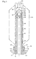
- Spindle 10 is mounted with its axis 16 upright and it receives in use over its upper end a hollow bobbin 18.
- the bobbin is passed down over the spindle until a frusto-conical shoulder 20 on the bobbin engages a frusto-conical end surface 22 on the upper end of the spindle.
- the bobbin rests on the surface 22 alone.
- Surface 22 is formed on an endcap 24 having a shank 26 screw-threaded into the open upper end of the spindle.
- the material of this endcap may be different from that of the remainder of the spindle, being suitably hardened if requred to form an accurate resting surface for the bobbin.
- the spindle has two diametrically opposite grooves 28 passing completely through its wall. Secured to the shank 26 are two leaf springs 30 projecting through respective grooves 28 so that portions of the springs extend radially outwardly beyond the external surface of the spindle.
- the outwardly extending portions of the springs pass into grooves formed between longitudinal, internal ribs 32 in the interior of the bobbin and form a positive driving connection with the bobbin - as seen on the left hand side of Fig. 1. Should the springs be initially aligned with ribs instead of grooves, they will be pressed inwardly against their own resilience (as seen on the right hand side of Fig.
- the internal diameter of the bobbin is larger than the external diameter of the spindle, and a centralising ring 34 is provided on the spindle below the centre of gravity of the bobbin.
- the spindle has an annular member 36 of trough section secured thereto, the open side of the trough facing upwardly and receiving the lower end of the bobbin.
- the inner wall 38 of the trough both secures it to the spindle and acts as a centering ring for the bobbin.
- the outer wall 40 of the trough has an inwardly projecting lip provided by a resilient ring 42 secured to wall 40 in any convenient manner.
- the ring presents a resilient socket to receive the lower end of the bobbin.
- a roving tail suitably presented to the bobbin and support structure can be clamped between the outer cylindrical surface of the bobbin and the resilient lip 42 and is thereby secured to the bobbin for winding of a package 44 thereon.
- a suitable flyer for presenting the tail to the spindle/bobbin is described in-our Swiss Patent Applications No. 6377/79 and 12089/79.
- Waste material can collect in the trough, which thereby protects the bearings in the bolster 12.
- the lower end face, that is the axially facing surface, 46 of the bobbin does not contact the bottan wall 48 of the trough so that the portion of the bobbin below shoulder 20 is dependent fran the shoulder and does not provide support for the weight of the bobbin or package.
- accumulated waste in the trough does not adversely affect the disposition of the bobbin.
- the lower end of the bobbin is provided by an array of teeth 50 which are evenly distributed around the full periphery of the bobbin.
- the roving tail passes into one of the gaps between the teeth when the bobbin first engages the ring 42, and the roving tail is thereby gathered together and supported and held in good condition for clamping. It will be noted that since clamping occurs between the lip 42 and an outwardly facing surface on the bobbin, i.e. a surface which does not produce any substantial force component support the bobbin, there is again no risk of disturbance of the disposition of the bobbin due to accumulated waste on the clamping surfaces.
- the head portion of the bobbin projects above the spindle and comprises a chamber 52 between the shoulder 20 and a second internal shoulder 54 which also faces the dependent end of the bobbin.
- the mouth of the bobbin bore at the head thereof is formed with an inwardly convergent frusto-conical surface 56.
- the head thus formed facilitates automatic doffing of the bobbin with a canpleted package, since a doffer element with spring or gravity loaded, radially outwardly projecting fingers can push into the bobbin head so that the fingers can engage under the shoulder 54 and lift the bobbin off the spindle.
- a so-called Casablanca connector is suitable for this purpose.
- the bobbin is made of synthetic plastics material.
- the outer wall of the bobbin is made as a generally uniform section tube (but formed with the ribs 32) and the shoulders at the head are provided by an additional part inserted into the outer wall and welded thereto.
- the bobbin support surface in the support structure may be on an element separate from the spindle which is required to hold the bobbin upright. However, it is clearly simpler to integrate the support and alignment functions in the one element.
- the internal shoulder which rests on the spindle is not necessarily continuous around the inner periphery of the bobbin. It could, for example, be provided by an array of sub-shoulders formed on the individual ribs 32, which can extend further upwards into the chamber 52.
- the position of the shoulder along the length of the bobbin can be varied, but preferably it is such as to enable use of the upper end of the spindle as the bobbin supporting surface thereon.
- the holder for the lip 42 is not necessarily formed as a trough, but it preferably has an undersurface protecting the bolster bearings. This can provide a labyrinth seal as seen at 58 in Figure 1.
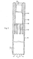
- Figure 2 illustrates the preferred form of the teeth 50, although this form is also not essential.
- the teeth have flanks disposed at an angle ⁇ , preferably about 60 degrees although 50 to 70 degrees is acceptable.
- Each tooth is short - about 3 mm is preferred, but 2 to 5 mm is acceptable.
- the spacing of the teeth at the lower edge of the bobbin may be about 5mm, although 4 to 7 nm is acceptable.
- the outside of each tooth is preferably chamfered, as indicated at B in Figure 2, to facilitate insertion into the lip clamp.
- a chamfer angle B of about 6 degrees is preferred although 4 to 8 degrees is acceptable.
- the overall dimensions of the bobbin will depend upon the size of package to be produced, the dimensions of the roving machine, the design of automatic doffer and a variety of other factors.
- An important feature is the selection of the length of the dependent portion of the bobbin, i.e. the distance between the shoulder 20 and the end surface 46 of the teeth 50, so that this portion will hang from the endcap 24 and will not rest on the base of the trough 36.
Landscapes
- Spinning Or Twisting Of Yarns (AREA)
- Winding Filamentary Materials (AREA)
- Braiding, Manufacturing Of Bobbin-Net Or Lace, And Manufacturing Of Nets By Knotting (AREA)
- Reciprocating, Oscillating Or Vibrating Motors (AREA)
- Moving Of Heads (AREA)
- Storage Of Web-Like Or Filamentary Materials (AREA)
Priority Applications (1)
| Application Number | Priority Date | Filing Date | Title |
|---|---|---|---|
| AT80105188T ATE11666T1 (de) | 1979-09-28 | 1980-09-01 | Spule und spulentraeger fuer einen vorgarnrahmen. |
Applications Claiming Priority (2)
| Application Number | Priority Date | Filing Date | Title |
|---|---|---|---|
| GB7933786 | 1979-09-28 | ||
| GB7933786A GB2059386B (en) | 1979-09-28 | 1979-09-28 | Bobbin and bobbin support for a roving frame |
Publications (3)
| Publication Number | Publication Date |
|---|---|
| EP0026340A2 true EP0026340A2 (fr) | 1981-04-08 |
| EP0026340A3 EP0026340A3 (en) | 1982-06-30 |
| EP0026340B1 EP0026340B1 (fr) | 1985-02-06 |
Family
ID=10508162
Family Applications (1)
| Application Number | Title | Priority Date | Filing Date |
|---|---|---|---|
| EP80105188A Expired EP0026340B1 (fr) | 1979-09-28 | 1980-09-01 | Bobine et support de bobine pour un cadre de mèche |
Country Status (9)
| Country | Link |
|---|---|
| EP (1) | EP0026340B1 (fr) |
| JP (1) | JPS5675351A (fr) |
| AT (1) | ATE11666T1 (fr) |
| AU (1) | AU544884B2 (fr) |
| BR (1) | BR8006187A (fr) |
| DE (2) | DE3070108D1 (fr) |
| ES (1) | ES8203113A1 (fr) |
| GB (1) | GB2059386B (fr) |
| IN (1) | IN157378B (fr) |
Cited By (2)
| Publication number | Priority date | Publication date | Assignee | Title |
|---|---|---|---|---|
| EP1595839A1 (fr) * | 2004-05-13 | 2005-11-16 | Novibra GmbH | L'embrayage entre un porte-fils et une partie supérieure d'une broche de filature ou à retordre |
| CN113968522A (zh) * | 2020-07-23 | 2022-01-25 | Ykk株式会社 | 线状体尾线保持夹具 |
Families Citing this family (2)
| Publication number | Priority date | Publication date | Assignee | Title |
|---|---|---|---|---|
| DE29712308U1 (de) * | 1997-07-15 | 1997-09-18 | CSM-Sächsische Spinnereimaschinen GmbH, 09120 Chemnitz | Wickeldorn für Faserbandwickel mit Wickelhülse |
| CN100347361C (zh) * | 2004-08-17 | 2007-11-07 | 江苏宏源纺机股份有限公司 | 筒管轴与筒管的连接方法 |
Family Cites Families (8)
| Publication number | Priority date | Publication date | Assignee | Title |
|---|---|---|---|---|
| BE533343A (fr) * | ||||
| CH236212A (de) * | 1939-04-24 | 1945-01-31 | Staufert Carl | Einrichtung zum Halten von Hülsen auf Spinnspindeln. |
| US2689692A (en) * | 1951-10-09 | 1954-09-21 | West Point Mfg Co | Bobbin |
| US2783954A (en) * | 1952-02-22 | 1957-03-05 | Courtaulds Ltd | Bobbin with tail-tie |
| CH545246A (de) * | 1971-10-22 | 1973-12-15 | Rieter Ag Maschf | Spanndorn für eine Hülse als Spulenträger |
| JPS4935089A (fr) * | 1972-08-03 | 1974-04-01 | ||
| JPS5237449B2 (fr) * | 1973-06-23 | 1977-09-22 | ||
| GB1474673A (en) * | 1975-01-29 | 1977-05-25 | Gutermann Co Ag | Spool for thread |
-
1979
- 1979-09-28 GB GB7933786A patent/GB2059386B/en not_active Expired
-
1980
- 1980-09-01 DE DE8080105188T patent/DE3070108D1/de not_active Expired
- 1980-09-01 AT AT80105188T patent/ATE11666T1/de not_active IP Right Cessation
- 1980-09-01 EP EP80105188A patent/EP0026340B1/fr not_active Expired
- 1980-09-26 BR BR8006187A patent/BR8006187A/pt unknown
- 1980-09-26 DE DE19803036349 patent/DE3036349A1/de not_active Withdrawn
- 1980-09-26 ES ES495763A patent/ES8203113A1/es not_active Expired
- 1980-09-26 AU AU62740/80A patent/AU544884B2/en not_active Ceased
- 1980-09-27 JP JP13507580A patent/JPS5675351A/ja active Pending
- 1980-09-27 IN IN1096/CAL/80A patent/IN157378B/en unknown
Cited By (3)
| Publication number | Priority date | Publication date | Assignee | Title |
|---|---|---|---|---|
| EP1595839A1 (fr) * | 2004-05-13 | 2005-11-16 | Novibra GmbH | L'embrayage entre un porte-fils et une partie supérieure d'une broche de filature ou à retordre |
| CN113968522A (zh) * | 2020-07-23 | 2022-01-25 | Ykk株式会社 | 线状体尾线保持夹具 |
| CN113968522B (zh) * | 2020-07-23 | 2024-05-03 | Ykk株式会社 | 线状体尾线保持夹具 |
Also Published As
| Publication number | Publication date |
|---|---|
| AU6274080A (en) | 1981-04-09 |
| EP0026340B1 (fr) | 1985-02-06 |
| BR8006187A (pt) | 1981-04-07 |
| ES495763A0 (es) | 1982-03-01 |
| GB2059386B (en) | 1983-07-06 |
| DE3070108D1 (en) | 1985-03-21 |
| AU544884B2 (en) | 1985-06-20 |
| JPS5675351A (en) | 1981-06-22 |
| DE3036349A1 (de) | 1981-04-16 |
| ES8203113A1 (es) | 1982-03-01 |
| GB2059386A (en) | 1981-04-23 |
| IN157378B (fr) | 1986-03-15 |
| ATE11666T1 (de) | 1985-02-15 |
| EP0026340A3 (en) | 1982-06-30 |
Similar Documents
| Publication | Publication Date | Title |
|---|---|---|
| US4428541A (en) | Bobbin and a bobbin support structure for a roving frame | |
| EP0026340A2 (fr) | Bobine et support de bobine pour un cadre de mèche | |
| US4736579A (en) | Variable length bobbin holder for a textile machine | |
| US3809326A (en) | Bobbin support chuck | |
| US4196575A (en) | Method for transfer of a fiber roving from a completed bobbin package to an empty tube on a spinning preparatory machine | |
| US4336912A (en) | Winding device | |
| US3368767A (en) | Textile pirn | |
| US2417525A (en) | Cop holding spindle for spinning or twisting yarn | |
| EP1213381A2 (fr) | Procédé et dispositif pour couper l'extrémité d'un fil pour des métiers à filer | |
| CN109023611B (zh) | 自由端型纺纱机 | |
| US3625452A (en) | Holders for bobbins in spinning and preparatory machines | |
| US4039159A (en) | Cone holder assembly | |
| US4339912A (en) | Device for gripping yarn supports on revolving-spindle textile machines | |
| CN1131707A (zh) | 纺纱装置 | |
| JP2994787B2 (ja) | 精紡機或いは撚糸機のスピンドル用糸切断装置 | |
| JPH0427152B2 (fr) | ||
| US3993266A (en) | Device for fastening yarn bobbins in looms | |
| EP0872583A2 (fr) | Dispositif pour identifier, saisir, positionner et manipuler des bobines | |
| US4422597A (en) | Carrier device for twister or bobbin tubes | |
| EP0417850A2 (fr) | Métier à retordre à double torsion avec une broche de deux arbres creuses et avec un accouplement d'arbres mobile | |
| US5292082A (en) | Device for driving the bobbin of a bank of spindles for long and short fibers | |
| US4399957A (en) | Yarn package holder | |
| US2220006A (en) | Spindle for strand wrapping | |
| EP0547712A2 (fr) | Porte bobine suspendu rotativement avec force de freinage ajustable et arrêtable | |
| CN1061707C (zh) | 在离心纺纱机上用以握持和更换筒管的装置 |
Legal Events
| Date | Code | Title | Description |
|---|---|---|---|
| PUAI | Public reference made under article 153(3) epc to a published international application that has entered the european phase |
Free format text: ORIGINAL CODE: 0009012 |
|
| AK | Designated contracting states |
Designated state(s): AT BE CH DE FR GB IT |
|
| 17P | Request for examination filed |
Effective date: 19811002 |
|
| PUAL | Search report despatched |
Free format text: ORIGINAL CODE: 0009013 |
|
| AK | Designated contracting states |
Designated state(s): AT BE CH DE FR GB IT |
|
| ITF | It: translation for a ep patent filed | ||
| GRAA | (expected) grant |
Free format text: ORIGINAL CODE: 0009210 |
|
| AK | Designated contracting states |
Designated state(s): AT BE CH DE FR GB IT LI |
|
| REF | Corresponds to: |
Ref document number: 11666 Country of ref document: AT Date of ref document: 19850215 Kind code of ref document: T |
|
| REF | Corresponds to: |
Ref document number: 3070108 Country of ref document: DE Date of ref document: 19850321 |
|
| ET | Fr: translation filed | ||
| PLBE | No opposition filed within time limit |
Free format text: ORIGINAL CODE: 0009261 |
|
| STAA | Information on the status of an ep patent application or granted ep patent |
Free format text: STATUS: NO OPPOSITION FILED WITHIN TIME LIMIT |
|
| 26N | No opposition filed | ||
| PGFP | Annual fee paid to national office [announced via postgrant information from national office to epo] |
Ref country code: FR Payment date: 19900816 Year of fee payment: 11 |
|
| PGFP | Annual fee paid to national office [announced via postgrant information from national office to epo] |
Ref country code: DE Payment date: 19900818 Year of fee payment: 11 |
|
| PGFP | Annual fee paid to national office [announced via postgrant information from national office to epo] |
Ref country code: GB Payment date: 19900820 Year of fee payment: 11 Ref country code: CH Payment date: 19900820 Year of fee payment: 11 |
|
| PGFP | Annual fee paid to national office [announced via postgrant information from national office to epo] |
Ref country code: BE Payment date: 19900821 Year of fee payment: 11 |
|
| PGFP | Annual fee paid to national office [announced via postgrant information from national office to epo] |
Ref country code: AT Payment date: 19900828 Year of fee payment: 11 |
|
| ITTA | It: last paid annual fee | ||
| PG25 | Lapsed in a contracting state [announced via postgrant information from national office to epo] |
Ref country code: GB Effective date: 19910901 Ref country code: AT Effective date: 19910901 |
|
| PG25 | Lapsed in a contracting state [announced via postgrant information from national office to epo] |
Ref country code: LI Effective date: 19910930 Ref country code: CH Effective date: 19910930 Ref country code: BE Effective date: 19910930 |
|
| BERE | Be: lapsed |
Owner name: MASCHINENFABRIK RIETER A.G. Effective date: 19910930 |
|
| GBPC | Gb: european patent ceased through non-payment of renewal fee | ||
| PG25 | Lapsed in a contracting state [announced via postgrant information from national office to epo] |
Ref country code: FR Effective date: 19920529 |
|
| REG | Reference to a national code |
Ref country code: CH Ref legal event code: PL |
|
| PG25 | Lapsed in a contracting state [announced via postgrant information from national office to epo] |
Ref country code: DE Effective date: 19920602 |
|
| REG | Reference to a national code |
Ref country code: FR Ref legal event code: ST |