EP0026439A2 - Haveuse pour une machine de creusement à attaque ponctuelle - Google Patents
Haveuse pour une machine de creusement à attaque ponctuelle Download PDFInfo
- Publication number
- EP0026439A2 EP0026439A2 EP80105723A EP80105723A EP0026439A2 EP 0026439 A2 EP0026439 A2 EP 0026439A2 EP 80105723 A EP80105723 A EP 80105723A EP 80105723 A EP80105723 A EP 80105723A EP 0026439 A2 EP0026439 A2 EP 0026439A2
- Authority
- EP
- European Patent Office
- Prior art keywords
- roller
- cutting machine
- partial
- chisels
- partial cutting
- Prior art date
- Legal status (The legal status is an assumption and is not a legal conclusion. Google has not performed a legal analysis and makes no representation as to the accuracy of the status listed.)
- Ceased
Links
- 238000005520 cutting process Methods 0.000 claims abstract description 87
- 230000001681 protective effect Effects 0.000 claims description 2
- 239000011435 rock Substances 0.000 description 6
- 239000003245 coal Substances 0.000 description 4
- 238000006073 displacement reaction Methods 0.000 description 3
- 230000005641 tunneling Effects 0.000 description 3
- 238000005299 abrasion Methods 0.000 description 1
- 230000005540 biological transmission Effects 0.000 description 1
- 238000006243 chemical reaction Methods 0.000 description 1
- 239000012530 fluid Substances 0.000 description 1
- 238000000034 method Methods 0.000 description 1
- 238000005065 mining Methods 0.000 description 1
- 239000007787 solid Substances 0.000 description 1
Images

Classifications
-
- E—FIXED CONSTRUCTIONS
- E21—EARTH OR ROCK DRILLING; MINING
- E21C—MINING OR QUARRYING
- E21C27/00—Machines which completely free the mineral from the seam
- E21C27/20—Mineral freed by means not involving slitting
- E21C27/24—Mineral freed by means not involving slitting by milling means acting on the full working face, i.e. the rotary axis of the tool carrier being substantially parallel to the working face
-
- E—FIXED CONSTRUCTIONS
- E21—EARTH OR ROCK DRILLING; MINING
- E21D—SHAFTS; TUNNELS; GALLERIES; LARGE UNDERGROUND CHAMBERS
- E21D9/00—Tunnels or galleries, with or without linings; Methods or apparatus for making thereof; Layout of tunnels or galleries
- E21D9/10—Making by using boring or cutting machines
- E21D9/1006—Making by using boring or cutting machines with rotary cutting tools
- E21D9/1013—Making by using boring or cutting machines with rotary cutting tools on a tool-carrier supported by a movable boom
- E21D9/1033—Making by using boring or cutting machines with rotary cutting tools on a tool-carrier supported by a movable boom by a transversely extending boom being pivotable about a longitudinal axis
Definitions
- the invention relates to a partial cutting machine with a longitudinal cutting head for driving sections of any cross section.
- Partial cutting machines are known for tunneling in hard coal mining, the cutting head of which is arranged at the end of a boom connected to the partial cutting machine, so that the entire surface of the working face can be coated.
- the cutting heads of these known partial cutting machines are equipped with round chisels or pin chisels. These chisels only have an insufficient service life and unsatisfactory cutting performance in solid, abrasive bedrock. In contrast, roller chisels, such as those used in full-cut machines, have significantly longer service lives and cutting performance, but also require correspondingly higher contact forces.
- the known partial cutting machines have a comparatively large overall length of over 10 meters, for which no suitable on-site expansion is available. It is therefore not possible to bring the final removal behind the machine continuously. Instead, the removal is attached to the face immediately after the cutting work, which in each case necessitates an interruption in the work of the partial cutting machine. This results in insufficient utilization of the part-cutting machine and thus an unsatisfactory opening result.
- the object of the present invention is the development of a partial cutting machine which enables high advance rates and allows the removal to be carried out without interrupting the line advance.
- the cutting head consists of an outer and an inner roller, the inner roller being arranged concentrically with the outer roller and being axially displaceable therein, and both the outer roller on its outer surface and the inner roller being equipped with chisels on the front and circumferential sides are, and that the cutting head is both radially displaceable and rotatable about an axis lying parallel to the cutting head axis with the partial cutting machine.
- the partial cutting machine equipped according to the invention enables high advance rates even with firm, abrasive rock in almost continuous operation.
- a pilot bore is first made with the inner roller of the rotating cutting head, preferably in soft rock or in coal, the diameter of which is at least corresponds to the diameter of the outer roller. This is done by extending the inner roller and moving the cutting head in the radial direction while simultaneously rotating about an axis lying parallel to the cutting head axis. Since both axial and vertical cutting forces act on the inner roller when the pilot bore is created, it has proven to be useful to equip it with conventional shank chisels. However, the abrasion of these chisels is limited because, as already mentioned, the pilot hole can be drilled in soft rock or in coal.
- the inner roller is retracted and at the same time the tunneling machine is advanced by the depth of the bore.
- the extension of the pilot bore in the circumferential direction to the desired cross-section of the working face now takes place exclusively via the outer roller of the cutting head, the cutting head now also being extended with simultaneous rotation in the radial direction. Since only vertical cutting forces act on the outer roller, it can be equipped with the more effective and less wear-resistant roller chisels.
- the power transmission poses no difficulties, since no unfavorable leverage arms are used. Rather, the required contact forces can be transmitted directly via corresponding hydraulic cylinders, which at the same time cause the cutting head to be displaced in the radial direction.
- connection between the cutting head and the partial cutting machine consists of a support arm, a profile rail and a carrier disc, the carrier disc being rotatable with the component cutting machine, the profile rail being rigid with the carrier disc, the carrier arm being radially displaceable with the profile rail and the cutting head is rigidly connected to the support arm.
- the partial cutting machine is clamped in the already opened section by hydraulic cylinders to absorb the reaction forces. Since the partial cutting machine according to the invention is very short, this tension and the now very small lever lengths mean that the high contact forces required for the use of roller chisels can be easily applied.
- the part-cutting machine is advanced in a manner known per se by means of hydraulic cylinders which are supported on an additional team and advance the machine body. By pushing these cylinders in the opposite direction, the additional team is pulled in turn.
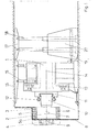
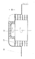
- the figures show a partial cutting machine 1 with a cutting head 2 connected to it in a force-locking manner.
- the cutting head 2 consists of an outer roller 3 equipped with roller chisels 5 and an inner roller 4 which is arranged concentrically with the outer roller and is axially displaceable and which is equipped with end chisels 9 on the face and circumference.
- the axes of rotation 6 of the roller chisels 5 lie parallel to the roller axis 7. Only the axes of the outer roller chisels 5a are slightly inclined in the direction of the face 8 in order to prevent the outer roller 3 from contacting the face 8.
- the axial displacement of the inner roller 3 is advantageously carried out via hydraulic units, not shown here.
- the non-positive connection between the cutting head 2 and the partial cutting machine 1 is made via a support arm 10, a profile rail 11 and a carrier disc 13, the carrier disc 13 being rotatable with the component cutting machine 1, the profile rail 11 rigid with the carrier disc 13, the carrier arm 10 is radially displaceable with the profile rail 11 and the support arm 10 is rigidly connected to the cutting head 2.
- the radial displacement of the support arm 10 and thus also of the cutting head 2 takes place by means of hydraulic cylinders 12, while the carrier disk 13 is generally driven by one or more hydraulic motors, not shown here.
- the cutting head 2 is also driven hydraulically, the hydraulic fluid being supplied to the hydraulic motor located in the support arm 10 via a rotary transducer.
- the cutting head 2 is centered again and after the inner roller 4 has been retracted, the partial cutting machine 1 is moved up a second time until the outer roller 3 engages the full length of the prepared pilot hole. Now, with the inner roller 4 retracted, the entire cross section can be covered, only the outer roller 3 being in engagement with the rock. Since the chisel bits 9 do not have a long service life in hard, abrasive rock, the pilot hole is, as far as possible, made in rock horizons that can be cut easily, for example in coal.
- the partial cutting machine 1 is braced in the course circumference via hydraulic cylinders 15, 18.
- Support plates 16, 17 in the ridge area of the section are advantageously designed as a protective roof for securing the section ridges and the upper section joints.
- the route extension itself can then be introduced in accordance with the advance of the partial cutting machine 1 without interrupting the tunneling work.
- the cylinders 15 are relieved, while the cylinders 18 remain loaded on an additional team 20.
- the partial cutting machine 1 is advanced by extending cylinders 19 which act between the partial cutting machine 1 and the combination 20. After tensioning the cylinders 15 and relieving the pressure on the cylinders 18, the cylinders 19 are acted upon in the opposite direction, the trailer 20 is tightened and then the cylinders 18 are tensioned again.
Landscapes
- Engineering & Computer Science (AREA)
- Mining & Mineral Resources (AREA)
- Life Sciences & Earth Sciences (AREA)
- General Life Sciences & Earth Sciences (AREA)
- Geochemistry & Mineralogy (AREA)
- Geology (AREA)
- Mechanical Engineering (AREA)
- Environmental & Geological Engineering (AREA)
- Road Repair (AREA)
- Turning (AREA)
- Earth Drilling (AREA)
Applications Claiming Priority (2)
| Application Number | Priority Date | Filing Date | Title |
|---|---|---|---|
| DE19792939087 DE2939087C2 (de) | 1979-09-27 | 1979-09-27 | Längsschneidkopf für eine Teilschnittstreckenvortriebsmaschine |
| DE2939087 | 1979-09-27 |
Publications (2)
| Publication Number | Publication Date |
|---|---|
| EP0026439A2 true EP0026439A2 (fr) | 1981-04-08 |
| EP0026439A3 EP0026439A3 (fr) | 1981-05-20 |
Family
ID=6081973
Family Applications (1)
| Application Number | Title | Priority Date | Filing Date |
|---|---|---|---|
| EP80105723A Ceased EP0026439A3 (fr) | 1979-09-27 | 1980-09-24 | Haveuse pour une machine de creusement à attaque ponctuelle |
Country Status (2)
| Country | Link |
|---|---|
| EP (1) | EP0026439A3 (fr) |
| DE (1) | DE2939087C2 (fr) |
Cited By (1)
| Publication number | Priority date | Publication date | Assignee | Title |
|---|---|---|---|---|
| US6569562B1 (en) | 1999-05-05 | 2003-05-27 | Wilson Greatbatch Ltd. | Electrochemical cell with novel header assembly |
Families Citing this family (1)
| Publication number | Priority date | Publication date | Assignee | Title |
|---|---|---|---|---|
| DE3421704C2 (de) * | 1984-06-12 | 1986-05-28 | Wirth Maschinen- und Bohrgeräte-Fabrik GmbH, 5140 Erkelenz | Vorrichtung zum Aufweiten des Querschnittsprofils eines Stollens, Tunnels od.dgl. |
Family Cites Families (12)
| Publication number | Priority date | Publication date | Assignee | Title |
|---|---|---|---|---|
| FR1212888A (fr) * | 1957-10-09 | 1960-03-28 | Steinkohlenbergwerk Hannover H | Machine de percement de galerie par avancement |
| GB913217A (en) * | 1958-08-09 | 1962-12-19 | Eickhoff Geb | Improvements in or relating to coal-getting machincs |
| DE1182618B (de) * | 1960-07-20 | 1964-12-03 | Eickhoff Geb | Vortriebsmaschine |
| FR1383686A (fr) * | 1964-03-06 | 1964-12-24 | Gewerk Eisenhuette Westfalia | Dispositif pour l'extraction automatique du charbon au moyen d'un cylindre équipé de pics de havage notamment sur sa périphérie |
| FR1445627A (fr) * | 1965-06-01 | 1966-07-15 | Charbonnages De France | Machine d'abattage du charbon ou autre |
| DE1277778B (de) * | 1965-07-09 | 1968-09-19 | Greenside Machine Company Ltd | Gewinnungs- oder Streckenvortriebsmaschine |
| DE1277779B (de) * | 1965-11-10 | 1968-09-19 | Aycliffe Ind Estate | Vortriebsmaschine fuer Strecken mit rechteckigem Querschnitt |
| DE1534612A1 (de) * | 1965-12-22 | 1969-08-21 | Demag Ag | Bohrkopf fuer eine Tunnelbohrmaschine |
| US3467436A (en) * | 1966-04-13 | 1969-09-16 | Mining Progress Inc | Tunnelling machine with rotatable cutter carrying arm for 360 cutting |
| GB1297141A (fr) * | 1969-01-04 | 1972-11-22 | ||
| DE2746169C2 (de) * | 1977-10-14 | 1984-05-10 | Gesteins- Und Tiefbau Gmbh, 4350 Recklinghausen | Längsschneidkopf für eine Teilschnittvortriebsmaschine, insbesondere für den Streckenvortrieb im Bergbau |
| PL213888A1 (fr) * | 1979-03-02 | 1980-11-03 | Ct Kt Maszyn Gorniczych Komag |
-
1979
- 1979-09-27 DE DE19792939087 patent/DE2939087C2/de not_active Expired
-
1980
- 1980-09-24 EP EP80105723A patent/EP0026439A3/fr not_active Ceased
Cited By (1)
| Publication number | Priority date | Publication date | Assignee | Title |
|---|---|---|---|---|
| US6569562B1 (en) | 1999-05-05 | 2003-05-27 | Wilson Greatbatch Ltd. | Electrochemical cell with novel header assembly |
Also Published As
| Publication number | Publication date |
|---|---|
| DE2939087C2 (de) | 1982-02-18 |
| DE2939087A1 (de) | 1981-04-02 |
| EP0026439A3 (fr) | 1981-05-20 |
Similar Documents
| Publication | Publication Date | Title |
|---|---|---|
| DE112009000325B4 (de) | Vortriebsmaschine mit Bohrkopf aus Diskenwerkzeugen | |
| DE4480466C2 (de) | Kombination aus einem Meißelhalter und einer austreibbaren Verschleißbüchse für eine Schrämmaschine | |
| DE69102883T2 (de) | Verfahren und maschine zum graben von strecken, tunneln, abbauräumen, kavernen oder dergleichen. | |
| DE2329487B2 (de) | Bohrkopf fuer eine streckenvortriebsmaschine | |
| WO2009100469A1 (fr) | Machine de creusement pourvue d'une tête de forage composée d'outils à disques | |
| DE10296375B4 (de) | Schild-Tunnelvortriebsverfahren und Schild-Tunnelvortriebsmaschine | |
| DE2639591A1 (de) | Schraemmaschine | |
| DE112013002922B4 (de) | Tunnelbau-Hilfsvorrichtung | |
| DE2810905C2 (de) | Streckenvortriebsmaschine | |
| DE112013002578B4 (de) | Tunnelvortriebsverfahren | |
| EP0849403B1 (fr) | Appareil excavateur à roues pour creuser des tranchées | |
| DE2615597A1 (de) | Erdbearbeitungseinrichtung fuer eine tunnelvortriebsmaschine | |
| CH644933A5 (de) | Schraemeinheitanordnung fuer eine vortriebsmaschine fuer strecken im bergbau und fuer tunnels und vortriebsmaschine. | |
| DE2939087C2 (de) | Längsschneidkopf für eine Teilschnittstreckenvortriebsmaschine | |
| DE2533500A1 (de) | Gesteinsbohrmaschine | |
| WO1986002697A1 (fr) | Foreuse a attaque partielle pour realiser des sections longitudinales en forme d'arc et respectant un profil precis | |
| DE3410121A1 (de) | Teilschnittmaschine mit zentral- und aussenwalze | |
| EP0453779B1 (fr) | Procédé et dispositif pour le fraisage de la paroi intérieure d'une canalisation souterraine | |
| EP0155540A1 (fr) | Appareil fonctionnant comme excavateur, pour la pose souterraine de tubes par poussage | |
| DE3140707C3 (de) | Streckenvortriebsmaschine | |
| DE3421704C2 (de) | Vorrichtung zum Aufweiten des Querschnittsprofils eines Stollens, Tunnels od.dgl. | |
| DE2514150C3 (de) | Schildvortriebsmaschine zum Auffahren von Tunneln und Strecken | |
| DE2065716C3 (de) | Verfahren zum Vortreiben eines Tunnels, eines Stollens o.dgl. und Vortriebsmaschine zur Durchführung dieses Verfahrens | |
| AT82656B (de) | Verfahren und Einrichtung zum Bohren von Stollen, Tunnels u. dgl. | |
| CH645696A5 (de) | Gleitbahneinrichtung und vortriebsmaschine, die mit der gleitbahneinrichtung ausgeruestet ist. |
Legal Events
| Date | Code | Title | Description |
|---|---|---|---|
| PUAI | Public reference made under article 153(3) epc to a published international application that has entered the european phase |
Free format text: ORIGINAL CODE: 0009012 |
|
| PUAL | Search report despatched |
Free format text: ORIGINAL CODE: 0009013 |
|
| AK | Designated contracting states |
Designated state(s): BE FR GB |
|
| AK | Designated contracting states |
Designated state(s): BE FR GB |
|
| 17P | Request for examination filed |
Effective date: 19811015 |
|
| STAA | Information on the status of an ep patent application or granted ep patent |
Free format text: STATUS: THE APPLICATION HAS BEEN REFUSED |
|
| 18R | Application refused |
Effective date: 19840714 |
|
| RIN1 | Information on inventor provided before grant (corrected) |
Inventor name: SCHMID, BERNHARD, DIPL.-ING. |