EP0026548A1 - Système pour la commande d'objets - Google Patents
Système pour la commande d'objets Download PDFInfo
- Publication number
- EP0026548A1 EP0026548A1 EP80200912A EP80200912A EP0026548A1 EP 0026548 A1 EP0026548 A1 EP 0026548A1 EP 80200912 A EP80200912 A EP 80200912A EP 80200912 A EP80200912 A EP 80200912A EP 0026548 A1 EP0026548 A1 EP 0026548A1
- Authority
- EP
- European Patent Office
- Prior art keywords
- high frequency
- radiator
- control
- control system
- control unit
- Prior art date
- Legal status (The legal status is an assumption and is not a legal conclusion. Google has not performed a legal analysis and makes no representation as to the accuracy of the status listed.)
- Withdrawn
Links
- 230000005540 biological transmission Effects 0.000 claims abstract description 25
- 238000001514 detection method Methods 0.000 claims abstract description 25
- 230000005855 radiation Effects 0.000 claims abstract description 8
- 230000035945 sensitivity Effects 0.000 claims abstract description 6
- 230000004913 activation Effects 0.000 claims description 30
- 239000003990 capacitor Substances 0.000 claims description 6
- WHXSMMKQMYFTQS-UHFFFAOYSA-N Lithium Chemical compound [Li] WHXSMMKQMYFTQS-UHFFFAOYSA-N 0.000 claims description 5
- 229910052744 lithium Inorganic materials 0.000 claims description 5
- 238000000034 method Methods 0.000 claims description 5
- 241000283690 Bos taurus Species 0.000 claims description 4
- 230000003213 activating effect Effects 0.000 claims description 4
- 238000004519 manufacturing process Methods 0.000 claims description 4
- 229910000859 α-Fe Inorganic materials 0.000 claims description 3
- 230000001276 controlling effect Effects 0.000 claims 2
- 230000001419 dependent effect Effects 0.000 description 3
- 206010012289 Dementia Diseases 0.000 description 2
- 238000010586 diagram Methods 0.000 description 2
- 230000004807 localization Effects 0.000 description 2
- 241000543375 Sideroxylon Species 0.000 description 1
- 239000004020 conductor Substances 0.000 description 1
- 238000010276 construction Methods 0.000 description 1
- 238000013016 damping Methods 0.000 description 1
- 230000000694 effects Effects 0.000 description 1
- 244000144972 livestock Species 0.000 description 1
- 238000004804 winding Methods 0.000 description 1
Images

Classifications
-
- G—PHYSICS
- G08—SIGNALLING
- G08C—TRANSMISSION SYSTEMS FOR MEASURED VALUES, CONTROL OR SIMILAR SIGNALS
- G08C17/00—Arrangements for transmitting signals characterised by the use of a wireless electrical link
- G08C17/02—Arrangements for transmitting signals characterised by the use of a wireless electrical link using a radio link
-
- G—PHYSICS
- G01—MEASURING; TESTING
- G01S—RADIO DIRECTION-FINDING; RADIO NAVIGATION; DETERMINING DISTANCE OR VELOCITY BY USE OF RADIO WAVES; LOCATING OR PRESENCE-DETECTING BY USE OF THE REFLECTION OR RERADIATION OF RADIO WAVES; ANALOGOUS ARRANGEMENTS USING OTHER WAVES
- G01S13/00—Systems using the reflection or reradiation of radio waves, e.g. radar systems; Analogous systems using reflection or reradiation of waves whose nature or wavelength is irrelevant or unspecified
- G01S13/74—Systems using reradiation of radio waves, e.g. secondary radar systems; Analogous systems
- G01S13/76—Systems using reradiation of radio waves, e.g. secondary radar systems; Analogous systems wherein pulse-type signals are transmitted
- G01S13/78—Systems using reradiation of radio waves, e.g. secondary radar systems; Analogous systems wherein pulse-type signals are transmitted discriminating between different kinds of targets, e.g. IFF-radar, i.e. identification of friend or foe
-
- G—PHYSICS
- G08—SIGNALLING
- G08C—TRANSMISSION SYSTEMS FOR MEASURED VALUES, CONTROL OR SIMILAR SIGNALS
- G08C2201/00—Transmission systems of control signals via wireless link
- G08C2201/50—Receiving or transmitting feedback, e.g. replies, status updates, acknowledgements, from the controlled devices
Definitions
- the invention relates to an object control system comprising a central control unit, a high frequency transmission generator, a control switching unit, a plurality of radiators for high frequency radiation, and a plurality of control units at a distance from the radiators, each control unit being associated with an object to be controlled.
- object control systems are known in practice.
- high frequency energy is applied from the high frequency transmission generator to a plurality of radiators via the control switching unit.
- These radiators when being controlled emit high frequency energy to a plurality of control units being at a distance from the radiators.
- the high frequency radiation received by a control unit when exceeding the detection threshold will cause a reaction in the control unit, whereupon this unit will implement its pre-instructed task.
- a selective object control system is used in order to obtain in unambiguous activation and if required to enable an object localisation.
- the maximum available high frequency for a selected radiator' is reduced in the central control switching unit due to cross talk or for another reason so that a portion of the high frequency signal energy lands in other radiators, an activation of a control unit being opposite to a non-selected radiator will take place in dependency of the distance.
- Such a cross talk may be avoided by using a completely unambiguous selecting control switching unit or by observing an unsafe area around each radiator. Said last measure in many cases is not useful especially when the control units are movable.
- the degree of cross talk is dependent on the amount of high frequency energy applied from the high frequency transmission generator via the control switching unit which amount is dependent on the power setting of the high-frequency transmission generator.
- the activation distance that means the distance to the radiator, in which the control unit may be activated by the incoming signal upon exceeding its detection threshold, depends on the power setting of the high frequency transmission generator.
- the cross talk us&y occurs during the switching operation in the control switching unit as it is difficult to switch high-frequency energy. Only with the aid of a complicated and bulky control switching unit a complete decoupling of the selected radiator with respect to the other non-selected radiators may be obtained with the aid for example of coaxial switches.
- the invention aims at providing an object control system which includes a very simple and compact control switching unit by which a complete unambiguous controlling operation and a certain controlling distance is obtained while using the maximum admissable high-frequency energy.
- the high frequency energy being applied by cross talk in the control switching unit to a non-selected radiator therefore is lead away by the choking operation of the associated disconnecting member and will not be emitted.
- each radiator in case it is not selected may be damped or choked.
- each well functioning radiator is tuned to a certain frequency, and said radiator will not function or badly when being detuned.
- control switching unit is a very compact and simple high frequency multiplexer which applies the high frequency signal to the selected radiators, whereby each radiator includes an energy transmission coil and a tuning coil with an adjusting element functioning as the disconnecting member, and whereby each control unit at least includes a receiving coil, a detection circuit being adjusted such that the control unit only within controlling distance to the selected radiator is enabled by its high frequency radiation, and a reaction circuit.
- the adjusting element of the tuning coil may be controlled from the multiplexer by a control voltage which is applied via a separate conductor or which is derived from the high frequency signal.
- the radiatpr for the activation of the adjusting element may have a supply source, like a lithium cell, which is switched by the control voltage.
- the adjusting element may be a voltage controlled capacitor or a capacitor which can be adjusted with the aid of an electronic or mechanical contact.
- each control unit includes also a power supply, such as a lithium cell, which is connected in the control unit such that the d'etection circuit is fed continuously and the reaction circuit is only fed during a reaction period following the exceeding of the detection switching threshold by the high frequency signal.
- the object control system may be used for the control of a production and/or regulation process, in which the objects associated and connected with the control units are implemented as operating and/or controlling members of the process.
- the object control system may also be used as an identification system for the identification of objects, such as living beings or things or articles, whereby the system additionally is provided with a receiving- and decoding circuit, whereby in each control unit the reaction circuit comprises a transmission circuit having a transmission coil and coding element which circuit upon being excited via the detection circuit supplies a code signal and whereby the control of the adjusting element of the tuning coil is such that the selected radiator upon activation by the high frequency signal is choked only after a period which is sufficient for the receipt on of the code signal.
- Such an identification system may be used advantageously for the identification of lifestock, such as cows in a stable, whereby the high frequency transmission generator is embodied and adjusted such that the high frequency power supplied to the radiator equals 200 mW, and that the detection circuit in the control unit with its sensitivety is embodied to a continuous current drain of 1 - 1.5 / uA, such that the activation distance is 1 or 2 meters.
- the -relay associated with the mechanical contact of the adjusting element may be embodied such that it drops off with a delay.
- the central control unit may be embodied as a central processing unit.
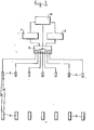
- the object control system comprises a highfrequency transmission generator 1, a receiving and decoding circuit 9, a central control unit 10, a control switching unit 2, a radiator 3 for high frequency radiation, a control or activation unit 4 associated with the object to be controlled and being at some distance with respect to the radiator 3.
- the transmission generator 1 for example includes a 30 MHz oscillator which supplies impulses of 1 - 20 msec.
- control switching unit 2 in which the high frequency power of the transmission generator 1 under control of the central control unit 10 is tranferred via the switch to a selected radiator. Only with the aid of an expensive implementation of the control switching unit, such as for example with the aid of coaxial and also bully switches this may be realized. However when a technically simple and compact control switching unit is applied one will have to accept a certain degree of cross talk in the switch, whereby this high frequency cross talk energy however in no case may initiate a undesired activation of an non-selected control unit. One requires a selective object control system for obtaining an unambiguous activation and if required an object localization.
- a portion of the energy destined for the selected radiator will land i on a non-selected radiator and will be emitted.
- the activation may take place of the control unit being opposite a non-selected radiator.
- Such a undesired activation of a non-selected control unit may be avoided by observing an unsafe zone at each radiator.
- an unsafe zone a and a desired activation distance b is indicated for an arbitrary radiator.
- a control unit being in the unsafe zone may also be activated.
- the magnitude of the unsafe zone dbviously is dependent on the adjustment of the high frequency transmission generator, on the degree of cross talk, and on the detection sensitivety of the control switching unit.
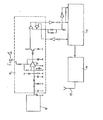
- Fig. 3 shows an example of a radiator according to the invention, which comprises a bar of ferrite on which an energy transmission coil having a supply lead 6 and a tuning coil 7 is mounted.
- the tuning coil 7 is also tuned with the aid of the adjusting element 8 which for example may comprise a variable capacitor.
- a selected radiator may emit the high frequency energy supplied to it in a maximum manner.
- the desadjustment or detuning in case of non-selection may be realized by changing the number of windings of the tuning coil, by changing the location of the tuning coil with respect to the energy trasmisssion coil, or by changes in the adjusting dement by which the tuning coil obtains a choking effect.
- a change in the adjusting element technically is the most simple one.
- the adjusting dement may be implemented as a voltage controlled capacitor, or as an adjustable and/or fixed capacitar, which may be adjusted with the aid of an electronic or mechanical contact of a relay for example.
- the control of the adjusting may be realized for example by a control voltage which is applied via an additional lead or which is derived from the high frequency signal.
- a supply source such as a lit ⁇ hium cell, may be taken up at the radiator, which source during the period of selection of the radiator may be switched by the control voltage of the additional lead or by the control voltage derived from the high frequency signal or by electromagnetic wireless radiation.
- the control units advantageously may be used in a production and/or contrdling process, in which the control units after being activated by their reaction circuit can emit a signal by which information is transmitted.
- the central control unit 10 may be embodied as a processor.
- the control unit also may be used for the control of adjusting members, such as valves, switches, etc.
- the activation distance between radiator and associated control unit(s),within which the emitted high frequency radiation may activate the control unit(s), is of great importance for the several possibilities of the system.Because of this activation distance also the number of control units in a certain space is determined as an unambigeous activation is required at all times.
- a disturbance insensitive object control system may be realized having a activation distance of 1 to 2 meters.
- control unit which is partially passive, which means that the continuous current drain of it is extremely low at a value of for example 1 to 1.5 / uA.
- the control unit consists as indicated of a detection circuit having a receiving coil, and a following reaction circuit.
- a control unit advantageously may have a power supply such as for example 2 lithium cells which feed the detection circuit continuously and feed the reaction circuit only during a certain reaction period following the exceeding of the detection threshold by the incoming signal.
- the reaction circuit therefore is switched in at a sufficiently strong input signal, and the circuit switches itself out after the end of the reaction period.
- Such a supply of these cells for example may function for a period of minimum ten years.
- the detection circuit of the control unit may be embodied'in a more active manner for obtaining a larger activation distance in a disturbance insensitive control system, whereby the current drain of the control unit increases.
- a disturbance insensitive detection circuit at a larger activation distance goes at the expence of the life time of the power supply and therefore of a sealed compact control unit.
- the mutual distance betwee two control units his to be maintained ma better manner in order to avoid that two control units are activated simultaneously. Because the whole system becomes more expensive, more complicated and vulnerable.
- control distance it is of importance to implement the control distance in an adjustable manner by means of the setting of the power of the high frequency transmission generator and/or by adjusting the detection sensitivity in the control unit.
- Each control unit may obtain a certain detection threshold by reason of the adjustability of the detection sensitivity.
- the disadvantage is to some degree that the control units, which some time occur in larger numbers than the radiators, then will differ mutually.
- the activation distance in a normal system embodiment may be made equal for each combination of radiator-control unit by embodying the high frequency transmission generator such that it can be adjusted.
- objects may be identified, such as living beings or articles. These articles for example may be moved in a production process or transportation process in accordance with a certain traject.
- the system advantageously may be also used for the identification of live-stock, such as for example cattle in a stable.
- the control unit 3 which is embodied for identification purposes,includes a detection circuit 11 having a receiving coil 12, and a reaction circuit consisting of a coder 13 and a transmission circuit 14 having an antenna or coil 13.
- a coder 13 a coding associated with the certain object, for example a certain cow, is set. After activation a coded signal may be emitted by this reaction circuit, which coded signal is received by the associated radiator or a central receiving antenna. In this manner information may be exchanged in the system.
- radiators having an adjusting _element it means that the radiator during the period of information exchange has to be tuned and should not be choked.
- control units having passive circuits which means only a continuously switched-in detection circuit and a normally switched-out reaction circuit, whereby a long live time for the internal power supply stays guaranteed, a reasonable high strong frequency signal has to be emitted by the high frequency transmission generator.
- the advantage is also that for activating the control unit by disturbing signals a relatively high disturbance level is required, by which also the activating distance is limited as the activation power is tied to a limit, such as 200 mwatt.
- the activation distance in the control system in most cases is smaller than the distance across which a signal could be received.
- the information emitted by the relative control unit and having the largest signal amplitude will then be recognized as the only true information by the receiving- and decoding circuit 9 of the control system. In this state two or more control units will be activated and controled simultaneously, only one of which is opposite the selected radiator.
- a plurality of control units may/be activated simultaneously, of which control units no one is opposite the selected radiator.
- the receiver then may receive false information from a contol unit which is activated by reason of cross talk.
Landscapes
- Engineering & Computer Science (AREA)
- Radar, Positioning & Navigation (AREA)
- Remote Sensing (AREA)
- Computer Networks & Wireless Communication (AREA)
- Physics & Mathematics (AREA)
- General Physics & Mathematics (AREA)
- Radar Systems Or Details Thereof (AREA)
- Charge And Discharge Circuits For Batteries Or The Like (AREA)
Applications Claiming Priority (2)
| Application Number | Priority Date | Filing Date | Title |
|---|---|---|---|
| NL7907250A NL7907250A (nl) | 1979-09-28 | 1979-09-28 | Objectaanstuurstelsel. |
| NL7907250 | 1979-09-28 |
Publications (1)
| Publication Number | Publication Date |
|---|---|
| EP0026548A1 true EP0026548A1 (fr) | 1981-04-08 |
Family
ID=19833943
Family Applications (1)
| Application Number | Title | Priority Date | Filing Date |
|---|---|---|---|
| EP80200912A Withdrawn EP0026548A1 (fr) | 1979-09-28 | 1980-09-26 | Système pour la commande d'objets |
Country Status (3)
| Country | Link |
|---|---|
| EP (1) | EP0026548A1 (fr) |
| NL (1) | NL7907250A (fr) |
| WO (1) | WO1981000927A1 (fr) |
Cited By (2)
| Publication number | Priority date | Publication date | Assignee | Title |
|---|---|---|---|---|
| RU2115171C1 (ru) * | 1995-08-10 | 1998-07-10 | Мальцев Петр Петрович | Устройство дистанционного динамического кодирования и идентификации различных объектов |
| WO1999066473A1 (fr) * | 1998-06-15 | 1999-12-23 | Siemens Aktiengesellschaft | Systeme d'automatisation avec detecteur radio |
Citations (16)
| Publication number | Priority date | Publication date | Assignee | Title |
|---|---|---|---|---|
| US2478409A (en) * | 1946-11-26 | 1949-08-09 | Hazeltine Research Inc | Time-sharing transpondor system |
| US2686900A (en) * | 1951-08-29 | 1954-08-17 | Westinghouse Electric Corp | Ionic switching tube |
| US3225265A (en) * | 1961-09-08 | 1965-12-21 | K & M Electronics Company | Remote control electrical switch and radio frequency actuating system therefor |
| US3371316A (en) * | 1963-06-21 | 1968-02-27 | Johnson Mcvoy | Radio control system |
| CH453140A (de) * | 1966-03-16 | 1968-05-31 | Willi Dipl Ing Menzel | Einrichtung zur drahtlosen elektrischen Übertragung physikalischer Zustandsgrössen von rotierenden Rädern zu nicht rotierenden Empfangsstellen |
| DE1939876A1 (de) * | 1969-08-06 | 1971-02-18 | Becker Flugfunkwerk Gmbh | Verfahren und Vorrichtung zum drahtlosen Steuern von Bewegungsablaeufen und Gegenstaenden |
| DE2056006A1 (de) * | 1970-11-13 | 1972-05-18 | Sel | Übertragungsverfahren zwischen gleichberechtigten Stationen einer Fernmelde-, insbesondere Funk-Fernsteueranlage |
| US3713163A (en) * | 1971-11-22 | 1973-01-23 | Nasa | Plural beam antenna |
| US3732496A (en) * | 1969-10-03 | 1973-05-08 | Cit Alcatel | Radio transmitter-received including means for automatically adjusting the transmission level |
| US3754250A (en) * | 1970-07-10 | 1973-08-21 | Sangamo Electric Co | Remote meter reading system employing semipassive transponders |
| DE2211313A1 (de) * | 1972-03-09 | 1973-09-13 | Bosch Elektronik Gmbh | Verfahren zum drahtlosen steuern von beweglichen objekten |
| DE2625017A1 (de) * | 1976-06-03 | 1977-12-15 | Walter Holzer | Einrichtung zur sicherung und auffindung von einem oder mehreren objekten |
| DE2748584A1 (de) * | 1976-11-01 | 1978-05-11 | Nedap Nv | Detektierplaettchen fuer ein identifizierungssystem |
| DE2747388A1 (de) * | 1977-10-21 | 1979-04-26 | Siemens Ag | Elektronisches kontrollsystem |
| DE2807887A1 (de) * | 1978-02-20 | 1979-08-30 | Alusuisse | Verfahren zur uebertragung von messdaten, anwendung des verfahrens sowie anordnung zur ausfuehrung des verfahrens |
| GB2019071A (en) * | 1978-04-13 | 1979-10-24 | Voxson Spa | Data Transmission Apparatus |
-
1979
- 1979-09-28 NL NL7907250A patent/NL7907250A/nl not_active Application Discontinuation
-
1980
- 1980-09-26 EP EP80200912A patent/EP0026548A1/fr not_active Withdrawn
- 1980-09-29 WO PCT/NL1980/000031 patent/WO1981000927A1/fr not_active Ceased
Patent Citations (16)
| Publication number | Priority date | Publication date | Assignee | Title |
|---|---|---|---|---|
| US2478409A (en) * | 1946-11-26 | 1949-08-09 | Hazeltine Research Inc | Time-sharing transpondor system |
| US2686900A (en) * | 1951-08-29 | 1954-08-17 | Westinghouse Electric Corp | Ionic switching tube |
| US3225265A (en) * | 1961-09-08 | 1965-12-21 | K & M Electronics Company | Remote control electrical switch and radio frequency actuating system therefor |
| US3371316A (en) * | 1963-06-21 | 1968-02-27 | Johnson Mcvoy | Radio control system |
| CH453140A (de) * | 1966-03-16 | 1968-05-31 | Willi Dipl Ing Menzel | Einrichtung zur drahtlosen elektrischen Übertragung physikalischer Zustandsgrössen von rotierenden Rädern zu nicht rotierenden Empfangsstellen |
| DE1939876A1 (de) * | 1969-08-06 | 1971-02-18 | Becker Flugfunkwerk Gmbh | Verfahren und Vorrichtung zum drahtlosen Steuern von Bewegungsablaeufen und Gegenstaenden |
| US3732496A (en) * | 1969-10-03 | 1973-05-08 | Cit Alcatel | Radio transmitter-received including means for automatically adjusting the transmission level |
| US3754250A (en) * | 1970-07-10 | 1973-08-21 | Sangamo Electric Co | Remote meter reading system employing semipassive transponders |
| DE2056006A1 (de) * | 1970-11-13 | 1972-05-18 | Sel | Übertragungsverfahren zwischen gleichberechtigten Stationen einer Fernmelde-, insbesondere Funk-Fernsteueranlage |
| US3713163A (en) * | 1971-11-22 | 1973-01-23 | Nasa | Plural beam antenna |
| DE2211313A1 (de) * | 1972-03-09 | 1973-09-13 | Bosch Elektronik Gmbh | Verfahren zum drahtlosen steuern von beweglichen objekten |
| DE2625017A1 (de) * | 1976-06-03 | 1977-12-15 | Walter Holzer | Einrichtung zur sicherung und auffindung von einem oder mehreren objekten |
| DE2748584A1 (de) * | 1976-11-01 | 1978-05-11 | Nedap Nv | Detektierplaettchen fuer ein identifizierungssystem |
| DE2747388A1 (de) * | 1977-10-21 | 1979-04-26 | Siemens Ag | Elektronisches kontrollsystem |
| DE2807887A1 (de) * | 1978-02-20 | 1979-08-30 | Alusuisse | Verfahren zur uebertragung von messdaten, anwendung des verfahrens sowie anordnung zur ausfuehrung des verfahrens |
| GB2019071A (en) * | 1978-04-13 | 1979-10-24 | Voxson Spa | Data Transmission Apparatus |
Non-Patent Citations (1)
| Title |
|---|
| FUNKSCHAU, vol. 41, no. 22, November 1969, pages 801-802, München, DE, G.P. VOSS: "Störsichere Funkfernsteuerung für Garagentore" * |
Cited By (2)
| Publication number | Priority date | Publication date | Assignee | Title |
|---|---|---|---|---|
| RU2115171C1 (ru) * | 1995-08-10 | 1998-07-10 | Мальцев Петр Петрович | Устройство дистанционного динамического кодирования и идентификации различных объектов |
| WO1999066473A1 (fr) * | 1998-06-15 | 1999-12-23 | Siemens Aktiengesellschaft | Systeme d'automatisation avec detecteur radio |
Also Published As
| Publication number | Publication date |
|---|---|
| WO1981000927A1 (fr) | 1981-04-02 |
| NL7907250A (nl) | 1981-03-31 |
Similar Documents
| Publication | Publication Date | Title |
|---|---|---|
| EP0878865B1 (fr) | Système d'antenne amélioré et procédé associé | |
| US5729236A (en) | Identification system reader with multiplexed antennas | |
| DE69030184D1 (de) | Steuerungssystem für die bewegungen von tieren | |
| US5923300A (en) | Multi-phase transmitter with single receive antenna for transponder interrogator | |
| US4806938A (en) | Integrated self-adaptive array repeater and electronically steered directional transponder | |
| US4352202A (en) | Combined remote control for wireless communication equipment and associated antenna | |
| DE69219629D1 (de) | Abfragestation zur Identifizierung mit separaten Sende- und Empfangsantennen | |
| ATE305670T1 (de) | Transpondernachrichtenübertragungsgerät | |
| CA2081752A1 (fr) | Transpondeur | |
| GB1423418A (en) | Method and installation for the detection of a source generating electromagnetic oscillations | |
| ES8705663A1 (es) | Un sistema de respondedor. | |
| EP0299557B1 (fr) | Système d'identification pour fermes d'élevage | |
| DE3373232D1 (en) | Detection system | |
| US4943803A (en) | Paging system with paging receivers controlled depending on location | |
| US3715749A (en) | Multi-beam radio frequency system | |
| EP0026548A1 (fr) | Système pour la commande d'objets | |
| GB1196191A (en) | Dual Antenna System for Transponder Beacon Devices | |
| US3042917A (en) | Antenna tracking system | |
| US11929771B2 (en) | Transmission system, antenna, control device, and transmission method | |
| KR920704453A (ko) | 가변 빔 영역을 보유한 신호빔을 가진 위성 신호 표시 시스템 | |
| US4757318A (en) | Phased array antenna feed | |
| EP2171637B1 (fr) | Système d'identification radiofréquence permettant un contrôle d'accès | |
| ATE174741T1 (de) | Verbesserungen in bezug auf satellitenantennen | |
| HU200881B (en) | System for identifying moving objects | |
| JPH0671224B2 (ja) | iDコ−ド収集方式 |
Legal Events
| Date | Code | Title | Description |
|---|---|---|---|
| PUAI | Public reference made under article 153(3) epc to a published international application that has entered the european phase |
Free format text: ORIGINAL CODE: 0009012 |
|
| AK | Designated contracting states |
Designated state(s): AT BE CH DE FR GB IT LU NL SE |
|
| STAA | Information on the status of an ep patent application or granted ep patent |
Free format text: STATUS: THE APPLICATION IS DEEMED TO BE WITHDRAWN |
|
| 18D | Application deemed to be withdrawn |
Effective date: 19820319 |