EP0026562A1 - Apparat zum Stapeln von Blättern und Sortiermaschinen mit einem solchen Apparat - Google Patents
Apparat zum Stapeln von Blättern und Sortiermaschinen mit einem solchen Apparat Download PDFInfo
- Publication number
- EP0026562A1 EP0026562A1 EP80302555A EP80302555A EP0026562A1 EP 0026562 A1 EP0026562 A1 EP 0026562A1 EP 80302555 A EP80302555 A EP 80302555A EP 80302555 A EP80302555 A EP 80302555A EP 0026562 A1 EP0026562 A1 EP 0026562A1
- Authority
- EP
- European Patent Office
- Prior art keywords
- sheet
- sheets
- bin
- tray
- bins
- Prior art date
- Legal status (The legal status is an assumption and is not a legal conclusion. Google has not performed a legal analysis and makes no representation as to the accuracy of the status listed.)
- Granted
Links
- 238000012384 transportation and delivery Methods 0.000 claims abstract description 10
- 230000037431 insertion Effects 0.000 claims 1
- 238000003780 insertion Methods 0.000 claims 1
- 239000011295 pitch Substances 0.000 description 8
- 230000001174 ascending effect Effects 0.000 description 2
- 238000000034 method Methods 0.000 description 2
- 230000003213 activating effect Effects 0.000 description 1
- 238000004140 cleaning Methods 0.000 description 1
- 238000003384 imaging method Methods 0.000 description 1
- 239000000463 material Substances 0.000 description 1
- 238000012986 modification Methods 0.000 description 1
- 230000004048 modification Effects 0.000 description 1
- 230000003287 optical effect Effects 0.000 description 1
- 239000003381 stabilizer Substances 0.000 description 1
- 230000001360 synchronised effect Effects 0.000 description 1
Images



Classifications
-
- B—PERFORMING OPERATIONS; TRANSPORTING
- B65—CONVEYING; PACKING; STORING; HANDLING THIN OR FILAMENTARY MATERIAL
- B65H—HANDLING THIN OR FILAMENTARY MATERIAL, e.g. SHEETS, WEBS, CABLES
- B65H39/00—Associating, collating, or gathering articles or webs
- B65H39/10—Associating articles from a single source, to form, e.g. a writing-pad
- B65H39/11—Associating articles from a single source, to form, e.g. a writing-pad in superposed carriers
-
- B—PERFORMING OPERATIONS; TRANSPORTING
- B65—CONVEYING; PACKING; STORING; HANDLING THIN OR FILAMENTARY MATERIAL
- B65H—HANDLING THIN OR FILAMENTARY MATERIAL, e.g. SHEETS, WEBS, CABLES
- B65H2405/00—Parts for holding the handled material
- B65H2405/10—Cassettes, holders, bins, decks, trays, supports or magazines for sheets stacked substantially horizontally
- B65H2405/11—Parts and details thereof
- B65H2405/111—Bottom
- B65H2405/1114—Bottom with surface portions curved in lengthwise direction
-
- B—PERFORMING OPERATIONS; TRANSPORTING
- B65—CONVEYING; PACKING; STORING; HANDLING THIN OR FILAMENTARY MATERIAL
- B65H—HANDLING THIN OR FILAMENTARY MATERIAL, e.g. SHEETS, WEBS, CABLES
- B65H2408/00—Specific machines
- B65H2408/10—Specific machines for handling sheet(s)
- B65H2408/11—Sorters or machines for sorting articles
- B65H2408/113—Sorters or machines for sorting articles with variable location in space of the bins relative to a stationary in-feed path
Definitions
- This invention relates to apparatus for collecting in a stack sheets delivered serially thereto face-up.
- face-up is meant in relation to a simplex sheet that the printed side of the sheet is upwards and in relation to a duplex sheet that the odd-numbered side is upwards.
- sheet collection apparatus including a tray for collecting in a stack sheets delivered serially thereto face-up, in which between the delivery of successive sheets the sheet or stack of sheets in the tray is raised above the tray support surface whereby the next sheet is delivered into the tray therebeneath.
- a sorter comprising an array of bins, a feed throat for delivering sheets to the bins, and means for indexing the bins past the feed throat to receive sheets in turn, characterised by retractable support means at the throat for supporting any sheets in a bin opposite the throat during delivery of a sheet thereto whereby the sheet enters the bin below the support means.
- sheets delivered to a collection tray in number order face-up are stacked in order.
- FIG. 1 there is shown an automatic xerographic reproducing machine 10 having a sheet collection apparatus 100 according to this invention for collecting copy sheets produced in the machine 10.
- a sheet collection apparatus 100 for collecting copy sheets produced in the machine 10.
- the present invention is particularly well suited for use in automatic xerography
- the apparatus 100 is equally well adapted for use with any number of devices in which cut sheets of material are delivered or compiled in a set or stack.
- the processor 10 includes a photosensitive drum 15 which is rotated in the direction indicated so as to pass sequentially through a series of xerographic processing stations: a charging station A, an imaging station B, a developer station C, a transfer station D and a cleaning station E.
- a document to be reproduced is placed on a platen 18 and scanned by means of a moving optical scanning system including lens 28 to produce a flowing light image on the drum at B.
- Cut sheets of paper are moved into the transfer station D from sheet registering apparatus 34 in synchronous relation with the image on the drum surface.
- the copy sheet is stripped from the drum surface and directed to a fusing station F.
- the fixed copy sheet is passed through a curvilinear sheet guide system, generally referred to as 49, incorporating advancing rolls 50 and 51.
- the advancing rolls forward the sheet through a linear sheet guide system 52 and to a second pair of advancing rollers 53 and 54. From here copy sheet is forwarded to the sheet collection apparatus 100 via pinch rolls 61, 62.
- the copy sheets S are delivered to the apparatus 100 face-up.
- the sheet collection apparatus 100 comprises a tray 101 into which sheets are delivered serially via the nip rolls 61, 62.
- the tray has a support surface 102 which extends in a convex curve between its input end and an end wall 103 at the far end of the tray.
- the tray has cut-outs 104 extending for nearly its full length along each side.
- Retractable bail bars 105 curved to match the profile of the surface 102, are dimensioned to fit into the cut-outs.
- the bail bars are movable between the positions shown in dotted lines in Figure 2 in which they form part of the tray support surface 102 and the retracted positions shown in full lines.
- the tray 101 is movable vertically between an upper position aligned with the bail bars 105 ( Figure 2) and a lower position below the bail bars in which it is aligned with the nip rollers 61, 62 ( Figure 1).
- the bail bars 105 are mounted on horizontal lead screws 106 supported in bearings-107.
- the lead screws 106 are driven from a motor 108 via shaft 109 and belts 110 entrained over pulleys 111.
- the tray 101 is mounted on a vertical lead screw 112 and driven from a motor 113.
- Copy sheets are delivered serially to the tray 101 face-up and the apparatus illustrated ensures that sheets arriving in ascending page-number order are stacked in ascending order in the tray. This is achieved in the following manner.
- the bail bars are advanced to their dotted line positions in the cut-outs 104 in line with the surface 102, by activating motor 108.
- the motor 113 is then activated to lower the tray 101 by rotating lead screw 112.
- the bail bars which are positioned beneath the opposite side edges of any sheets already stacked in the tray, support the sheets as the tray is lowered, the curved form of the bail bars serving to increase the beam strength of the stacked sheets and ensure that they do not bend laterally.
- the tray With the tray lowered the next sheet is advanced into the tray through the nip rollers 61, 62. The tray is then raised and the bail bars retracted to their full-line positions. The new sheet is now correctly positioned at the bottom of the stack and the process is repeated for each sheet feed into the tray.
- FIG. 3 there is illustrated a sorter 120 according to the invention.
- the sorter is attached to the output end of a photocopier 10 from which sheets are serially delivered through exit slot 11 by means of exit nip rollers 12, 14.
- the sorter has ten bins B1-B10 which are arranged to be indexed past the exit slot 11 of the copier so that successive sheets may be received in respective bins.
- the bins B together with the sorter mechanism are mounted on a frame 122 and are enclosed by a cover 123.
- the whole sorter assembly is hingedly connected to the copier at 124 so that it may be swung away as illustrated in outline in Figures 3 and 4 to obtain access to the sorter.
- the front side of the sorter i.e. the side facing the viewer in Figure 3, is open for access to the bins for removal of the sheets collected therein.
- the bins B comprise support surfaces 125 which extend in a convex curve, best seen in Figure 3, between their input ends adjacent the exit slot 11 and end walls 126 at their opposite ends.
- a guide plate 127 overlies the far end of the uppermost bin.
- the bins are mounted as a unit 128 for vertical movement between a lowermost position, as shown in Figure 3 and an uppermost position shown in Figure 4. In the latter position the lowermost bin is positioned slightly above the exit slot 11 and sheets may be delivered into a catch tray below the array 121 of bins.
- This tray which is particularly suitable for sheets which are too wide to be received in the bins has a guide surface 129 which moves with the bin unit 121.
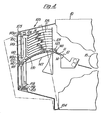
- a pair of bail bars 130 profiled to match the curvature of the bins 121, are arranged at opposite sides of the bin unit 121 as seen in Figures 5 and 6.
- the bail bars are vertically fixed but movable laterally of the bins between an outer position spaced from the bins as shown in the drawings and an inner position alongside the bins. In their outer positions the bail bars are spaced apart by a distance which is greater than the length of the largest sheet of paper which can be received in the bins.
- the sheets- are centre-registered so that different-sized sheets have the same centre-line and the bail bars are symmetrically arranged.
- the bail bars are asymmetrically arranged in their outer positions. In their inner positions they are symmetrically arranged next to the bins, so that the rear bail bar moves further between its inner and outer positions than the front bail bar.
- the bins may be indexed past the exit slot 11 upwardly or downwardly.
- the bail bars are moved to their outer positions.
- the bin unit is driven upwardly until the top bin B1 is above the bail arms which are then moved inwardly below the edges of any sheets already in the bin.
- the bin unit is then moved downwardly into register with the exit slot 11, leaving the sheets supported on the bail arms.
- a sheet is now ejected through slot 11 by nip rollers 12, 14 into the bin B1, face-up, following which the bail arms are moved outwards allowing the sheets thereon to fall on to the sheet just delivered.
- the bin unit is now driven upwardly until bin B2 is above the bail arms and the bail arms are returned to their inner positions; as the bin unit is indexed down to bring bin B2 into alignment with slot 11, the sheets in that bin are supported by the bail bars. Following sheet delivery the bail bars are retracted as before to compile the B2 sheets and the process is repeated for bin B3, etc.
- bin B10 For upward indexing, bin B10 is raised above the bail bars, the latter being in their outer positions, and then lowered into alignment with the exit slot 11ir the bail bars supporting sheets already in bin B10. After a sheet has been delivered into bin B10, it is raised and simultaneously the bail bars are retracted so that the sheets are compiled in bin B10. Lifting of the bin unit is continued until bin B9 is just above the bail bars. The loading sequence is now repeated for bin B9 and again for the other bins.
- the sorter maybe programmed to sort sheets into sets of less than ten in which case it will index past only the appropriate number of bins. It may be arranged to operate unidirectionally being returned in a single movement to its start position at the end of each indexing pass or it may be arranged to operate bidirectionally, indexing past the exit slot in both upwardly and downwardly.
- the sorter may be programmed so that it will also operate in non-sort mode in which successive sheets are delivered to the same bin, e.g. B10.
- the mechanism by which the bail bars are moved laterally and the bins are indexed vertically will now be described. They are driven from a common motor 140.
- the bail bars are carried by screw blocks 141 mounted on a pair of horizontal lead screws 142, 143 supported in bearings 144.
- the lead screw 142 is driven off motor 140 via gears 145, 146 and the lead screw 143 is driven from the screw 142 via a timing belt 147 entrained over pulleys 148. Because of the asymmetrical movement of the bail bars described above, the pitches of the lead screws 142, 143 are different at each end so that the rear bail bar moves faster than the front bail bar.
- the bin unit is mounted by means of screw blocks 149a on a vertical lead screw 149 and stabilised by slide blocks 149b running on a stabiliser bar 150.
- the lead screw 149 is driven off the drive shaft 140a of motor 140 through a timing belt 151 entrained over pulleys 152, 153.
- the lead-screw 149 is splined to a drive shaft 154 to which the pulley 153 is fixed.
- the assembly is rotatably mounted in bearings 155, 156 and the splined connection between the shaft 154 and the lead-screw 148 allows the latter to slide vertically on the drive shaft while being rotatable with the drive shaft.
- the bin assembly 121 is indexed by a camming mechanism 157 which includes a face cam 158 fixed on the bottom end of the lead-screw 148 and a cam follower 159 fixed to the sorter frame 122.
- the pitch of lead-screw 148 is equal to the spacing between adjacent bins (bin pitch) so that a single revolution of the lead screw performs an indexing movement of the bin unit or array.
- the cam 158 is profiled for indexing of the bin array by continuous rotation of the drive shaft 154.
- One revolution of the drive shaft causes the bin unit to rise one and a half bin pitches and then fall half a pitch in one cycle.
- the rise and fall of the bin array is timed in order to allow the bail bars to achieve their correct position to support the existing sheets in the relevant bin.
- the cam first raises the bin above the bail bars and then lowers it into alignment with the exit slot 11, the bail bars supporting the sheets already in the bin.
- a dwell time corresponding to the time taken for delivery of the sheet into the bin completes the revolution and the cam again-raises the bin array by one and a half bin pitches to commence the next indexing pass.
- each sheet enters an empty bins o that the friction characteristics for sheet delivery remain the same regardless of how many sheets have already been delivered.
Landscapes
- Collation Of Sheets And Webs (AREA)
- Cleaning By Liquid Or Steam (AREA)
- Counters In Electrophotography And Two-Sided Copying (AREA)
- Control Or Security For Electrophotography (AREA)
Applications Claiming Priority (2)
| Application Number | Priority Date | Filing Date | Title |
|---|---|---|---|
| GB7926266 | 1979-07-27 | ||
| GB7926266 | 1979-07-27 |
Publications (2)
| Publication Number | Publication Date |
|---|---|
| EP0026562A1 true EP0026562A1 (de) | 1981-04-08 |
| EP0026562B1 EP0026562B1 (de) | 1984-11-28 |
Family
ID=10506824
Family Applications (1)
| Application Number | Title | Priority Date | Filing Date |
|---|---|---|---|
| EP80302555A Expired EP0026562B1 (de) | 1979-07-27 | 1980-07-25 | Apparat zum Stapeln von Blättern und Sortiermaschinen mit einem solchen Apparat |
Country Status (5)
| Country | Link |
|---|---|
| US (1) | US4353542A (de) |
| EP (1) | EP0026562B1 (de) |
| JP (1) | JPS5621147A (de) |
| CA (1) | CA1143324A (de) |
| DE (2) | DE3028325A1 (de) |
Families Citing this family (18)
| Publication number | Priority date | Publication date | Assignee | Title |
|---|---|---|---|---|
| JPS5874458A (ja) * | 1981-10-28 | 1983-05-04 | Konishiroku Photo Ind Co Ltd | ソ−タの制御方法 |
| US4570918A (en) * | 1984-11-19 | 1986-02-18 | Xerox Corporation | Feeder and bottom stacker |
| DE3528575A1 (de) * | 1985-08-06 | 1987-02-19 | Schering Ag | Verfahren und einrichtung zur reinigung, aktivierung und/oder metallisierung von bohrloechern in horizontal gefuehrten leiterplatten |
| US5014972A (en) * | 1985-12-02 | 1991-05-14 | Ricoh Company, Ltd. | Recirculating automatic document feeder |
| US4703923A (en) * | 1985-12-02 | 1987-11-03 | Ricoh Co. Ltd. | Recirculating automatic document feeder |
| JPH0524687Y2 (de) * | 1986-03-26 | 1993-06-23 | ||
| DE3638630A1 (de) * | 1986-11-11 | 1988-05-26 | Schering Ag | Verfahren zur entfernung von harzverschmutzungen in bohrloechern von leiterplatten |
| US4836526A (en) * | 1987-09-29 | 1989-06-06 | Xerox Corporation | Sheet sorters |
| US5138681A (en) * | 1988-04-18 | 1992-08-11 | Minnesota Mining And Manufacturing Company | Optical fiber splice |
| US5189717A (en) * | 1988-04-18 | 1993-02-23 | Minnesota Mining And Manufacturing Company | Optical fiber splice |
| US5159653A (en) * | 1988-04-18 | 1992-10-27 | Minnesota Mining And Manufacturing Company | Optical fiber splice |
| DE3840098C1 (de) * | 1988-11-28 | 1989-12-21 | Helmut Walter 8900 Augsburg De Leicht | |
| DE4103098C1 (de) * | 1991-02-01 | 1992-06-25 | Helmut Walter 8901 Koenigsbrunn De Leicht | |
| US5686950A (en) * | 1994-05-09 | 1997-11-11 | Canon Kabushiki Kaisha | Mounting device and a recording apparatus including the same |
| US7711310B2 (en) * | 2004-03-15 | 2010-05-04 | Fuji Xerox Co., Ltd. | Image-forming apparatus and multiple sheet curl correcting sheet-receiving units |
| US7673873B2 (en) * | 2004-06-14 | 2010-03-09 | Eastman Kodak Company | Offset print stacking tray with anti-stubbing feature |
| US20100295240A1 (en) * | 2009-05-20 | 2010-11-25 | Xerox Corporation | Large format stacking tray for an image production device |
| JP5730487B2 (ja) * | 2010-01-15 | 2015-06-10 | 富士フイルム株式会社 | 送風装置および送風方法 |
Citations (5)
| Publication number | Priority date | Publication date | Assignee | Title |
|---|---|---|---|---|
| US3833911A (en) * | 1972-12-29 | 1974-09-03 | Xerox Corp | Reproduction system and method with simplex and duplex modes of operation |
| US3938802A (en) * | 1972-12-29 | 1976-02-17 | Xerox Corporation | Sheet stacking apparatus |
| US3977667A (en) * | 1974-12-09 | 1976-08-31 | Xerox Corporation | Sorting apparatus |
| US4111410A (en) * | 1977-03-31 | 1978-09-05 | Xerox Corporation | Sorting apparatus and reproducing machine |
| US4116429A (en) * | 1977-04-04 | 1978-09-26 | Xerox Corporation | Sorting apparatus and reproducing machine |
Family Cites Families (17)
| Publication number | Priority date | Publication date | Assignee | Title |
|---|---|---|---|---|
| US2224606A (en) * | 1939-10-16 | 1940-12-10 | American Laundry Mach Co | Stacking device |
| US2426957A (en) * | 1945-05-26 | 1947-09-02 | Gen Aniline & Film Corp | Means for receiving sheet material for printing machines |
| US2488675A (en) * | 1948-03-20 | 1949-11-22 | American Laundry Mach Co | Stacking mechanism |
| US2595346A (en) * | 1948-09-04 | 1952-05-06 | Scriptomatic Inc | Stacking device for cards or the like |
| US3212774A (en) * | 1964-01-06 | 1965-10-19 | James E Ingalls | Stacking apparatus |
| US3396966A (en) * | 1966-02-03 | 1968-08-13 | Gen Electric | Sheet stacking apparatus |
| NL7005222A (de) * | 1970-04-10 | 1971-10-12 | ||
| DE2239397A1 (de) * | 1971-10-05 | 1973-04-12 | Volkswerft Stralsund Veb | Schaltungsanordnung zur erzeugung von stromimpulsen, insbesondere zur beeinflussung von lebewesen im wasser |
| US3744649A (en) * | 1972-05-05 | 1973-07-10 | Ward Machinery Co | Squaring and bundle counting machine |
| JPS49111363A (de) * | 1973-02-26 | 1974-10-23 | ||
| JPS5326747B2 (de) * | 1973-03-05 | 1978-08-03 | ||
| US3971554A (en) * | 1975-01-09 | 1976-07-27 | Xerox Corporation | Sheet stacker |
| US4026540A (en) * | 1975-06-10 | 1977-05-31 | Lawrence Frederick J | Selective tray sheet sorting machine |
| US4068767A (en) * | 1976-08-09 | 1978-01-17 | Honeywell Information Systems Inc. | Transfer mechanism |
| US4068837A (en) * | 1976-09-29 | 1978-01-17 | International Business Machines Corporation | Paper hold-down device for collector |
| DE2800846C3 (de) * | 1978-01-10 | 1981-11-05 | Bielomatik Leuze Gmbh + Co, 7442 Neuffen | Vorrichtung zum Aufbringen von Abschlußblättern o.dgl. auf Blattlagen |
| US4190354A (en) * | 1978-10-30 | 1980-02-26 | Xerox Corporation | Copier job recovery system |
-
1980
- 1980-07-21 JP JP9972980A patent/JPS5621147A/ja active Pending
- 1980-07-22 CA CA000356707A patent/CA1143324A/en not_active Expired
- 1980-07-25 EP EP80302555A patent/EP0026562B1/de not_active Expired
- 1980-07-25 US US06/172,497 patent/US4353542A/en not_active Expired - Lifetime
- 1980-07-25 DE DE19803028325 patent/DE3028325A1/de not_active Withdrawn
- 1980-07-25 DE DE8080302555T patent/DE3069701D1/de not_active Expired
Patent Citations (5)
| Publication number | Priority date | Publication date | Assignee | Title |
|---|---|---|---|---|
| US3833911A (en) * | 1972-12-29 | 1974-09-03 | Xerox Corp | Reproduction system and method with simplex and duplex modes of operation |
| US3938802A (en) * | 1972-12-29 | 1976-02-17 | Xerox Corporation | Sheet stacking apparatus |
| US3977667A (en) * | 1974-12-09 | 1976-08-31 | Xerox Corporation | Sorting apparatus |
| US4111410A (en) * | 1977-03-31 | 1978-09-05 | Xerox Corporation | Sorting apparatus and reproducing machine |
| US4116429A (en) * | 1977-04-04 | 1978-09-26 | Xerox Corporation | Sorting apparatus and reproducing machine |
Also Published As
| Publication number | Publication date |
|---|---|
| DE3069701D1 (en) | 1985-01-10 |
| US4353542A (en) | 1982-10-12 |
| JPS5621147A (en) | 1981-02-27 |
| DE3028325A1 (de) | 1981-02-19 |
| CA1143324A (en) | 1983-03-22 |
| EP0026562B1 (de) | 1984-11-28 |
Similar Documents
| Publication | Publication Date | Title |
|---|---|---|
| US4353542A (en) | Sheet collection apparatus and sorters incorporating same | |
| CA1155789A (en) | Finishing station for collating machine | |
| CA1071664A (en) | Pre-separated recirculating document copying system | |
| US4824091A (en) | Sheet collection devices and sheet processors utilizing same | |
| JPH0446869B2 (de) | ||
| US5101241A (en) | Telescopic paper guide means movable to selected receiving trays | |
| US4866487A (en) | Image forming apparatus | |
| JP3535573B2 (ja) | 画像形成装置およびシート収納装置 | |
| EP0049097B1 (de) | Kombinierter Blattwender und -sortierer | |
| US5078385A (en) | Sorting apparatus having variable length guide plates | |
| JP2608367B2 (ja) | シート後処理装置 | |
| GB2240328A (en) | Shifting bin array for sorting sheets | |
| EP0482643B1 (de) | Einen Hefter enthaltender Sortierer | |
| US5105231A (en) | Image formation apparatus having means for reversing the order of stacking of image bearing documents | |
| JPH05265277A (ja) | デュプレックス・フィーダ | |
| US4398712A (en) | Sheet sorters | |
| JPH023504B2 (de) | ||
| EP0666510B1 (de) | Blattnachbearbeitungsvorrichtung | |
| EP0163485B1 (de) | Sortiergerät mit Fächern mit gemeinsamem Drehpunkt | |
| US6708972B2 (en) | Sheet-like object sorter, and discharged paper processing device for image-forming apparatus employing the same | |
| JP3413058B2 (ja) | 画像形成装置 | |
| GB2141111A (en) | Adjustable sheet tray in duplex copier | |
| GB2152014A (en) | Collating sheets | |
| JPH0532231A (ja) | 画像形成装置の後処理装置及びそれによる封筒の開封方法 | |
| JPS60112568A (ja) | シ−ト分類装置 |
Legal Events
| Date | Code | Title | Description |
|---|---|---|---|
| PUAI | Public reference made under article 153(3) epc to a published international application that has entered the european phase |
Free format text: ORIGINAL CODE: 0009012 |
|
| AK | Designated contracting states |
Designated state(s): DE FR GB |
|
| 17P | Request for examination filed |
Effective date: 19810723 |
|
| GRAA | (expected) grant |
Free format text: ORIGINAL CODE: 0009210 |
|
| AK | Designated contracting states |
Designated state(s): DE FR GB |
|
| REF | Corresponds to: |
Ref document number: 3069701 Country of ref document: DE Date of ref document: 19850110 |
|
| ET | Fr: translation filed | ||
| PLBE | No opposition filed within time limit |
Free format text: ORIGINAL CODE: 0009261 |
|
| STAA | Information on the status of an ep patent application or granted ep patent |
Free format text: STATUS: NO OPPOSITION FILED WITHIN TIME LIMIT |
|
| 26N | No opposition filed | ||
| PGFP | Annual fee paid to national office [announced via postgrant information from national office to epo] |
Ref country code: FR Payment date: 19890613 Year of fee payment: 10 |
|
| PGFP | Annual fee paid to national office [announced via postgrant information from national office to epo] |
Ref country code: GB Payment date: 19890630 Year of fee payment: 10 |
|
| PGFP | Annual fee paid to national office [announced via postgrant information from national office to epo] |
Ref country code: DE Payment date: 19890831 Year of fee payment: 10 |
|
| PG25 | Lapsed in a contracting state [announced via postgrant information from national office to epo] |
Ref country code: GB Effective date: 19900725 |
|
| GBPC | Gb: european patent ceased through non-payment of renewal fee | ||
| PG25 | Lapsed in a contracting state [announced via postgrant information from national office to epo] |
Ref country code: FR Effective date: 19910329 |
|
| PG25 | Lapsed in a contracting state [announced via postgrant information from national office to epo] |
Ref country code: DE Effective date: 19910403 |
|
| REG | Reference to a national code |
Ref country code: FR Ref legal event code: ST |