EP0027098A1 - Procédé et dispositif de fabrication de tubes en matière plastique renforcés longitudinalement - Google Patents
Procédé et dispositif de fabrication de tubes en matière plastique renforcés longitudinalement Download PDFInfo
- Publication number
- EP0027098A1 EP0027098A1 EP80810264A EP80810264A EP0027098A1 EP 0027098 A1 EP0027098 A1 EP 0027098A1 EP 80810264 A EP80810264 A EP 80810264A EP 80810264 A EP80810264 A EP 80810264A EP 0027098 A1 EP0027098 A1 EP 0027098A1
- Authority
- EP
- European Patent Office
- Prior art keywords
- tube
- fiber elements
- longitudinal
- rollers
- pipe
- Prior art date
- Legal status (The legal status is an assumption and is not a legal conclusion. Google has not performed a legal analysis and makes no representation as to the accuracy of the status listed.)
- Granted
Links
Images




Classifications
-
- B—PERFORMING OPERATIONS; TRANSPORTING
- B29—WORKING OF PLASTICS; WORKING OF SUBSTANCES IN A PLASTIC STATE IN GENERAL
- B29C—SHAPING OR JOINING OF PLASTICS; SHAPING OF MATERIAL IN A PLASTIC STATE, NOT OTHERWISE PROVIDED FOR; AFTER-TREATMENT OF THE SHAPED PRODUCTS, e.g. REPAIRING
- B29C70/00—Shaping composites, i.e. plastics material comprising reinforcements, fillers or preformed parts, e.g. inserts
- B29C70/04—Shaping composites, i.e. plastics material comprising reinforcements, fillers or preformed parts, e.g. inserts comprising reinforcements only, e.g. self-reinforcing plastics
- B29C70/06—Fibrous reinforcements only
- B29C70/10—Fibrous reinforcements only characterised by the structure of fibrous reinforcements, e.g. hollow fibres
- B29C70/16—Fibrous reinforcements only characterised by the structure of fibrous reinforcements, e.g. hollow fibres using fibres of substantial or continuous length
-
- B—PERFORMING OPERATIONS; TRANSPORTING
- B29—WORKING OF PLASTICS; WORKING OF SUBSTANCES IN A PLASTIC STATE IN GENERAL
- B29C—SHAPING OR JOINING OF PLASTICS; SHAPING OF MATERIAL IN A PLASTIC STATE, NOT OTHERWISE PROVIDED FOR; AFTER-TREATMENT OF THE SHAPED PRODUCTS, e.g. REPAIRING
- B29C53/00—Shaping by bending, folding, twisting, straightening or flattening; Apparatus therefor
- B29C53/80—Component parts, details or accessories; Auxiliary operations
- B29C53/8008—Component parts, details or accessories; Auxiliary operations specially adapted for winding and joining
- B29C53/8016—Storing, feeding or applying winding materials, e.g. reels, thread guides, tensioners
-
- B—PERFORMING OPERATIONS; TRANSPORTING
- B29—WORKING OF PLASTICS; WORKING OF SUBSTANCES IN A PLASTIC STATE IN GENERAL
- B29C—SHAPING OR JOINING OF PLASTICS; SHAPING OF MATERIAL IN A PLASTIC STATE, NOT OTHERWISE PROVIDED FOR; AFTER-TREATMENT OF THE SHAPED PRODUCTS, e.g. REPAIRING
- B29C53/00—Shaping by bending, folding, twisting, straightening or flattening; Apparatus therefor
- B29C53/80—Component parts, details or accessories; Auxiliary operations
- B29C53/8008—Component parts, details or accessories; Auxiliary operations specially adapted for winding and joining
- B29C53/805—Applying axial reinforcements
- B29C53/8058—Applying axial reinforcements continuously
-
- B—PERFORMING OPERATIONS; TRANSPORTING
- B29—WORKING OF PLASTICS; WORKING OF SUBSTANCES IN A PLASTIC STATE IN GENERAL
- B29C—SHAPING OR JOINING OF PLASTICS; SHAPING OF MATERIAL IN A PLASTIC STATE, NOT OTHERWISE PROVIDED FOR; AFTER-TREATMENT OF THE SHAPED PRODUCTS, e.g. REPAIRING
- B29C70/00—Shaping composites, i.e. plastics material comprising reinforcements, fillers or preformed parts, e.g. inserts
- B29C70/04—Shaping composites, i.e. plastics material comprising reinforcements, fillers or preformed parts, e.g. inserts comprising reinforcements only, e.g. self-reinforcing plastics
- B29C70/06—Fibrous reinforcements only
- B29C70/10—Fibrous reinforcements only characterised by the structure of fibrous reinforcements, e.g. hollow fibres
- B29C70/16—Fibrous reinforcements only characterised by the structure of fibrous reinforcements, e.g. hollow fibres using fibres of substantial or continuous length
- B29C70/20—Fibrous reinforcements only characterised by the structure of fibrous reinforcements, e.g. hollow fibres using fibres of substantial or continuous length oriented in a single direction, e.g. roofing or other parallel fibres
- B29C70/205—Fibrous reinforcements only characterised by the structure of fibrous reinforcements, e.g. hollow fibres using fibres of substantial or continuous length oriented in a single direction, e.g. roofing or other parallel fibres the structure being shaped to form a three-dimensional configuration
- B29C70/207—Fibrous reinforcements only characterised by the structure of fibrous reinforcements, e.g. hollow fibres using fibres of substantial or continuous length oriented in a single direction, e.g. roofing or other parallel fibres the structure being shaped to form a three-dimensional configuration arranged in parallel planes of fibres crossing at substantial angles
-
- B—PERFORMING OPERATIONS; TRANSPORTING
- B29—WORKING OF PLASTICS; WORKING OF SUBSTANCES IN A PLASTIC STATE IN GENERAL
- B29L—INDEXING SCHEME ASSOCIATED WITH SUBCLASS B29C, RELATING TO PARTICULAR ARTICLES
- B29L2023/00—Tubular articles
- B29L2023/22—Tubes or pipes, i.e. rigid
Definitions
- the invention relates to a method for producing longitudinally reinforced pipes and a device for carrying out this method.
- plastic tubes such as resin-impregnated fiber tubes of the type disclosed in US Pat. Nos. 3,700,519 and 4,053,343
- continuous fiber elements such as glass fiber strands or glass rows
- the tube is turned on a spindle and continuously advanced in the axial direction.
- Several winding stations are normally used to build up layers of resin-impregnated fibers on the conveyor tube.
- the tube so produced generally has a circumferential strength, but the axial strength is low owing to the absence of longitudinal fibers in the tube. Accordingly, additional steps have to be taken to provide the desired longitudinal reinforcement.
- Plastic pipes have always been more difficult and expensive than reinforcing the circumference.
- One type of longitudinal reinforcement of plastic pipe is that a fiber-reinforced tape is applied to the pipe in the longitudinal direction during the winding process. This is expensive and complicates the manufacture of the tube in an impermissible manner.
- the additional fibers are deposited on the tube as loops or loops at a rate greater than the rate at which the circumferential fibers are wound up, and are generally arranged lengthways to form a resin impregnated mat which rests on the support layer of Peripheral fibers is worn and is hereby wound together on the tube. This technique does not allow precise control of the longitudinal reinforcement deposit.
- the circumferential fiber elements are first passed through a Haribad and then over a pair of rollers which are in contact with the surface of the tube being produced.
- Longitudinal reinforcement fiber elements are deposited on the surface of the tube in the inlet gap in a reciprocating pattern from a feed tube which is pivoted with its outlet, which is located near the inlet gap, in an arc substantially parallel to the longitudinal axis of the tube.
- the rollers feed the fibers from the feed tube lengthways onto the tube.
- the fibers that are wound onto the pipe in the circumferential direction hold the longitudinal fibers in place against the pipe surface and coat them with resin.
- the method according to the invention and the device for its implementation comprise the laying down of longitudinal reinforcing fiber elements directly on the surface of the tube into the inlet gap which is formed between the surface of the tube which is being produced and the fiber elements which extend circumferentially on the tube Tube can be wound. Rollers which are in contact with the tube at the inlet gap preferably form a guide for the longitudinal laying down of the fiber elements which are fed in from a pivoted feed tube.
- a plastic tube 10 such as a resin-impregnated fiber reinforced tube
- a plastic tube 10 has been continuously produced as described, for example, in the aforementioned U.S. Patents 3,700,519 and 4,053,343, the disclosure of which is incorporated by reference is expressly included in these documents, rotated counterclockwise on a spindle (not shown) and at the same time advanced in the axial direction A parallel to a longitudinal axis.
- the pipe is advanced at a speed which is significantly less than its speed of rotation.
- a plurality of fiber elements 12 which may be a plurality of continuous fiber strands or fiber rows comprising two or more strands, such as glass, are withdrawn from a supply spool (not shown), passed through a resin bath 14 and circumferentially onto the surface 16 of the rotating one Tube coiled.
- the circumferential fiber elements 12 When the circumferential fiber elements 12 are wound onto the tube, they are pulled over a pair of rollers 20, 22 which are in contact with and rotate with the surface of the tube. The fiber elements 12 cause the rollers to be held in close engagement against the glass-resin tube surface so that the rollers press the fiber elements against the tube.
- a substantially S-shaped feed tube 24 for feeding the longitudinal reinforcing fiber elements 26 has an outlet end 28 which is arranged near the rollers 20, 22.
- the longitudinal fiber elements exiting the feed tube are deposited on the surface of the tube in the inlet gap 30 formed between the surface of the tube and the peripheral fiber elements 12 which just being wound onto the pipe at the point where the circumferential fiber elements are pressed into contact with the pipe surface by the rollers.
- the rollers touch the pipe surface of the inlet gap.
- the feed tube which is preferably made of light steel or in lightweight steel construction, is connected at its opposite end 32 to a gear mechanism 34 for pivoting the tube back and forth.
- the inlet end 32 of the feed tube is pivoted such that its outlet end 28 moves in an arc, the plane of which is substantially parallel to the longitudinal axis of the tube and the inlet gap. Since the feed tube swings alternately from one side to the other, the fiber elements 26 are first caught between the one roll and the surface of the rotating pipe and then between the other roll and the pipe surface. In this way, the fiber elements are pulled through the pivoting feed tube and fed back and forth in the longitudinal direction and onto the tube surface through the rollers. The fiber elements are laid on the tube in a sinusoidal or reciprocating pattern or revolution 27, the extension being substantially longitudinal to reinforce the tube in the longitudinal direction.
- the circumferential fiber elements 12 touch that are just wrapped around the tube, immediately the fiber elements 26 so that they hold them in place on the surface of the tube and cover them with resin.
- the guiding effect of the rollers when the fiber elements are deposited from the vibrating feed tube in the longitudinal direction on the tube, in combination with the holding effect of the circumferential fiber elements, ensures control over the laying pattern of the longitudinal reinforcing fiber elements.
- Each completed cycle of feed tube reciprocation places an arc 27 of longitudinal fiber elements on the tube.
- adjacent arcs are circumferentially spaced around the tube.
- the speed at which the tube swings determines the circumferential distance d between adjacent bends in association with the speed of rotation of the tube.
- the axial speed of the pipe feed per revolution determines the longitudinal distance 1 between the bends. Accordingly, by controlling these speeds, the amount of longitudinal reinforcement applied to the pipe can be controlled, and the axial strength of the pipe can be controlled.
- controllable factors that affect the amount of longitudinal reinforcement applied to the pipe include the yield (m / kg) of the total number of strands of longitudinal reinforcement fiber elements that are fed into tube 24, the distance from the end of one Role at the end of other roll, which determines the length of the sheets deposited on the tube and the sheet length over which the feed tube pivots. _
- a plurality of longitudinal fiber elements 26 can be fed through the feed tube 24.
- the longitudinal fiber elements as well as the circumferential fiber elements 12 can either be a plurality of individual fiber strands or a plurality of rowings which comprise two or more fiber strands. It is an advantage of the invention that the longitudinal reinforcement fiber elements can belong to the same type of standard rowings as the fiber rowings used for the circumferential reinforcement, since they are the least expensive available.
- the longitudinal fiber elements 26 are fed to the tube 24 through a guide 36 from a fixed coil frame 38. Since the bobbin rack is stationary, it can be refilled if necessary without stopping the machine. This is a major advantage in a continuous pipe manufacturing process. Similarly, the circumferential fiber elements 12 may also be fed from stationary spool racks (not shown) as taught by the aforementioned U.S. patents.
- the circumferential fiber elements 12 which are wound on the tube are surrounded by the resin bath 14 around the guides 40, 42, 44 out where they are covered with resin.
- the guide 42 can have a plurality of pins 43 in order to spread the fiber elements apart in the longitudinal direction.
- the resin-impregnated fiber elements are then guided around the guide 46 to the rollers 20, 22.
- the rollers 20, 22 and the guide 46 can be carried by an arm 50 which is pivotally mounted for rotation at one end 51 on a fixed arm 52 which in turn is attached to a frame 54.
- the frame 54 can similarly support other parts of the device, such as a tub 56 for receiving the resin bath, the gear mechanism 34, and the drive mechanism for the gear mechanism.
- the gear mechanism which notifies the feed tube 24 of the pivotal movement, is driven by a motor (not shown) by a belt 58, a pulley 59 and a crank wheel 60.
- the motor may include a variable speed drive (also not shown) to control the speed of the motor in a known manner, and thus the speed of movement of the feed tube.
- An arm 62 is attached to the crank wheel and connects to an arm 64 of the transmission mechanism. When the crank wheel rotates, arm 64 reciprocates. preferably over an angle of 30 °, causing the feed tube to move in and out.
- Gear mechanism 34 is preferably a 4: 1 ratio gear so that pivoting arm 64 by 30 ° produces movement of outlet end 28 of the delivery tube through an arc of 120 °.
- the movement of the feed tube generated by the gear mechanism is approximated to a simple, harmonic movement which is desired to apply a uniform pattern of longitudinal reinforcement.
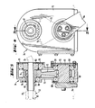
- the gear mechanism essentially comprises a shaft 66, which is supported for rotation by means of bearings 68 in a frame 70 and is attached to an arm 64.
- the feed tube 24 runs through a bore in the axis of rotation of the gear 74 and is attached thereto by means of a sleeve 80.
- sector gear 72 pivots back and forth, causing gear 74 and feed tube 24 to reciprocate, with the outlet end 28 of the feed tube a pivoting movement is communicated.
- the inlet end 32 of the delivery tube may have a sleeve 81 (Fig. 5) which has a rounded inner portion 82 at its inlet to guide the fiber elements 26 as they are pulled through the delivery tube.
- FIGS. 6 to 8 illustrate another embodiment in which two feed tubes 86, 88 arranged to pivot in opposite directions are used to feed the longitudinal fiber members 26, 26 'to the tube. Their movement is controlled by a gear mechanism 90, which is similar to gear mechanism 34, except that a third gear 92 is coupled to gear 74 for rotation in the opposite direction to gear 74. Accordingly, when the sector gear 72 swings back and forth under the action of the arm 64, the feed tubes 86 and 88 that pass through and are attached to the bores of the gears 74 and 92, respectively, pivot in opposite arcs.
- the details of the gear mechanism 90 are shown in FIGS. 7 and 8, where components that perform functions similar to those of FIGS. 4 and 5 have the same reference numerals.
- FIGS. 6 to 8 allows a larger amount of longitudinal reinforcement to be applied to the tube to provide greater axial strength.
Landscapes
- Engineering & Computer Science (AREA)
- Mechanical Engineering (AREA)
- Textile Engineering (AREA)
- Chemical & Material Sciences (AREA)
- Composite Materials (AREA)
- Moulding By Coating Moulds (AREA)
- Rigid Pipes And Flexible Pipes (AREA)
Priority Applications (1)
| Application Number | Priority Date | Filing Date | Title |
|---|---|---|---|
| AT80810264T ATE7672T1 (de) | 1979-08-30 | 1980-08-25 | Verfahren und einrichtung zur herstellung von laengsverstaerkten kunststoffrohren. |
Applications Claiming Priority (2)
| Application Number | Priority Date | Filing Date | Title |
|---|---|---|---|
| US71053 | 1979-08-30 | ||
| US06/071,053 US4308999A (en) | 1979-08-30 | 1979-08-30 | Method and apparatus for longitudinally reinforcing continuously generated plastic pipe |
Publications (2)
| Publication Number | Publication Date |
|---|---|
| EP0027098A1 true EP0027098A1 (fr) | 1981-04-15 |
| EP0027098B1 EP0027098B1 (fr) | 1984-05-30 |
Family
ID=22098953
Family Applications (1)
| Application Number | Title | Priority Date | Filing Date |
|---|---|---|---|
| EP80810264A Expired EP0027098B1 (fr) | 1979-08-30 | 1980-08-25 | Procédé et dispositif de fabrication de tubes en matière plastique renforcés longitudinalement |
Country Status (6)
| Country | Link |
|---|---|
| US (1) | US4308999A (fr) |
| EP (1) | EP0027098B1 (fr) |
| JP (1) | JPS5664834A (fr) |
| AT (1) | ATE7672T1 (fr) |
| CA (1) | CA1145234A (fr) |
| DE (1) | DE3068034D1 (fr) |
Cited By (2)
| Publication number | Priority date | Publication date | Assignee | Title |
|---|---|---|---|---|
| EP0582215A1 (fr) * | 1992-08-07 | 1994-02-09 | Sedepro | Procédé de fabrication d'un pneumatique et machine de fabrication d'un renfort de sommet pour pneumatique |
| EP1977880A1 (fr) * | 2007-04-05 | 2008-10-08 | Vem S.P.A. | Distributeur axial de roving pour une machine adaptée à la fabrication d'éléments tubulaires en matériau composite |
Families Citing this family (23)
| Publication number | Priority date | Publication date | Assignee | Title |
|---|---|---|---|---|
| US7498509B2 (en) * | 1995-09-28 | 2009-03-03 | Fiberspar Corporation | Composite coiled tubing end connector |
| US5921285A (en) | 1995-09-28 | 1999-07-13 | Fiberspar Spoolable Products, Inc. | Composite spoolable tube |
| US8678042B2 (en) | 1995-09-28 | 2014-03-25 | Fiberspar Corporation | Composite spoolable tube |
| US6004639A (en) | 1997-10-10 | 1999-12-21 | Fiberspar Spoolable Products, Inc. | Composite spoolable tube with sensor |
| US6179945B1 (en) | 1998-12-30 | 2001-01-30 | Owens Corning Fiberglas Technology, Inc. | Process for filament winding composite workpieces |
| US20020185188A1 (en) * | 2001-04-27 | 2002-12-12 | Quigley Peter A. | Composite tubing |
| US20030087052A1 (en) * | 2001-11-05 | 2003-05-08 | Wideman Thomas W. | Spoolable composite tubing with a catalytically cured matrix |
| US6978804B2 (en) * | 2002-03-29 | 2005-12-27 | Fiberspar Corporation | Systems and methods for pipeline rehabilitation |
| US7523765B2 (en) * | 2004-02-27 | 2009-04-28 | Fiberspar Corporation | Fiber reinforced spoolable pipe |
| FR2882681B1 (fr) * | 2005-03-03 | 2009-11-20 | Coriolis Composites | Tete d'application de fibres et machine correspondante |
| US8187687B2 (en) * | 2006-03-21 | 2012-05-29 | Fiberspar Corporation | Reinforcing matrix for spoolable pipe |
| US8839822B2 (en) * | 2006-03-22 | 2014-09-23 | National Oilwell Varco, L.P. | Dual containment systems, methods and kits |
| CA2619808C (fr) * | 2007-02-02 | 2015-04-14 | Fiberspar Corporation | Tube multicellulaire enroulable |
| US8746289B2 (en) | 2007-02-15 | 2014-06-10 | Fiberspar Corporation | Weighted spoolable pipe |
| CA2641492C (fr) * | 2007-10-23 | 2016-07-05 | Fiberspar Corporation | Conduite chauffee et methodes de transport de fluide visqueux |
| US9127546B2 (en) * | 2009-01-23 | 2015-09-08 | Fiberspar Coproation | Downhole fluid separation |
| CN102803646B (zh) | 2009-12-15 | 2016-04-20 | 菲伯斯公司 | 用于从地下井去除流体的系统和方法 |
| US8955599B2 (en) | 2009-12-15 | 2015-02-17 | Fiberspar Corporation | System and methods for removing fluids from a subterranean well |
| US20110210542A1 (en) * | 2010-02-23 | 2011-09-01 | Makselon Christopher E | Connector for Spoolable Pipe |
| JP5695189B2 (ja) * | 2010-05-25 | 2015-04-01 | エイデ, モートンEIDE, Morten | 少なくとも一つの硬化性固着剤コートされた糸をコア要素上に巻き付けることによって細長い物体を製造する方法 |
| WO2014026190A1 (fr) | 2012-08-10 | 2014-02-13 | National Oilwell Varco, L.P. | Raccords de tubulure enroulés composites |
| US12377616B2 (en) | 2021-12-23 | 2025-08-05 | Hexagon Technology As | Device for stabilizing localized dome reinforcement |
| CN115847860B (zh) * | 2023-02-06 | 2023-04-28 | 西南石油大学 | 一种用于玄武岩纤维复合管的旋转复合成型装置 |
Citations (6)
| Publication number | Priority date | Publication date | Assignee | Title |
|---|---|---|---|---|
| FR1363100A (fr) * | 1962-07-20 | 1964-06-05 | B C M Plastic Developments Ltd | Procédé et machine pour la fabrication de tuyaux et corps creux analogues cylindriques ou à section transversale courbe ainsi que les produits conformes à ceux obtenus par ledit procédé ou procédé similaire |
| US3700519A (en) * | 1969-05-13 | 1972-10-24 | Ciba Geigy Corp | Methods of forming a fiber reinforced pipe on an inflatable mandrel |
| US3791900A (en) * | 1971-02-09 | 1974-02-12 | Bayer Ag | Process and apparatus for the production of hollow bodies from reaction resins, which are reinforced with fibres |
| DE2658979A1 (de) * | 1975-12-31 | 1977-07-14 | Olof Sundell | Verfahren und vorrichtung fuer die zufuehrung von armierungsdraht bei der herstellung eines roherzeugnisses |
| US4053343A (en) * | 1973-05-10 | 1977-10-11 | Ciba-Geigy Corporation | Methods of making fiber reinforced plastic pipe |
| DE2060261B2 (de) * | 1969-12-10 | 1978-07-13 | Peder Ulrik Fredensborg Poulsen (Daenemark) | Verfahren zum Herstellen eines Rohres aus faserverstärktem Kunststoff sowie Verfahren zur Durch führung des Verfahrens |
Family Cites Families (16)
| Publication number | Priority date | Publication date | Assignee | Title |
|---|---|---|---|---|
| US3113738A (en) * | 1958-08-01 | 1963-12-10 | Pirelli | Machine for forming annular bands |
| US3232545A (en) * | 1963-08-15 | 1966-02-01 | Taylor Corp | Filament winding machine |
| US3303079A (en) * | 1963-08-23 | 1967-02-07 | Richard P Carter | Method of manufacture of rocket chambers having an integral insulator or liner |
| US3708131A (en) * | 1966-04-01 | 1973-01-02 | Union Carbide Corp | Method of and apparatus for wrapping layered composite thermal insulation |
| FR1529729A (fr) * | 1967-04-25 | 1968-06-21 | R D T Soc Pour L Etude | Tube en fibres de verre et résine synthétique, procédé et machine pour sa fabrication |
| US3721599A (en) * | 1968-05-20 | 1973-03-20 | Deering Milliken Res Corp | Method and apparatus for securing a continuous thread on a support surface |
| US3631897A (en) * | 1970-06-22 | 1972-01-04 | Herbert Corliss Fischer | Prestressed tubular article |
| DE2036513C3 (de) * | 1970-07-23 | 1980-06-12 | Glanzstoff Ag | Verfahren zur Herstellung rotationssymmetrischer Hohlkörper aus glasfaserverstärkten Kunststoffen |
| US3729365A (en) * | 1970-09-03 | 1973-04-24 | Deering Milliken Res Corp | Endless reinforcement and method for producing same |
| US3748203A (en) * | 1971-04-12 | 1973-07-24 | Deering Milliken Res Corp | Method and apparatus for positioning a plurality of continuous stripson a support surface |
| US3761341A (en) * | 1971-04-12 | 1973-09-25 | Deering Milliken Res Corp | Apparatus for guiding a strip to a support surface |
| US4010054A (en) * | 1971-05-03 | 1977-03-01 | Albert L. Jeffers | Thermoplastic filament winding process |
| GB1415975A (en) * | 1972-07-02 | 1975-12-03 | Jense W F | Device for manufacturing a non-woven reticulate textile strip |
| JPS518941A (ja) * | 1974-07-11 | 1976-01-24 | Ricoh Kk | Joyogenzoekijokyosochi |
| JPS5146528A (en) * | 1974-10-18 | 1976-04-21 | Matsushita Electric Industrial Co Ltd | Aennnitsukeruusuzugokinmetsukyodenkaieki |
| US4089720A (en) * | 1975-11-28 | 1978-05-16 | Monsanto Company | Method and apparatus for making a nonwoven fabric |
-
1979
- 1979-08-30 US US06/071,053 patent/US4308999A/en not_active Expired - Lifetime
-
1980
- 1980-08-25 AT AT80810264T patent/ATE7672T1/de not_active IP Right Cessation
- 1980-08-25 DE DE8080810264T patent/DE3068034D1/de not_active Expired
- 1980-08-25 EP EP80810264A patent/EP0027098B1/fr not_active Expired
- 1980-08-28 CA CA000359217A patent/CA1145234A/fr not_active Expired
- 1980-08-28 JP JP11787880A patent/JPS5664834A/ja active Granted
Patent Citations (6)
| Publication number | Priority date | Publication date | Assignee | Title |
|---|---|---|---|---|
| FR1363100A (fr) * | 1962-07-20 | 1964-06-05 | B C M Plastic Developments Ltd | Procédé et machine pour la fabrication de tuyaux et corps creux analogues cylindriques ou à section transversale courbe ainsi que les produits conformes à ceux obtenus par ledit procédé ou procédé similaire |
| US3700519A (en) * | 1969-05-13 | 1972-10-24 | Ciba Geigy Corp | Methods of forming a fiber reinforced pipe on an inflatable mandrel |
| DE2060261B2 (de) * | 1969-12-10 | 1978-07-13 | Peder Ulrik Fredensborg Poulsen (Daenemark) | Verfahren zum Herstellen eines Rohres aus faserverstärktem Kunststoff sowie Verfahren zur Durch führung des Verfahrens |
| US3791900A (en) * | 1971-02-09 | 1974-02-12 | Bayer Ag | Process and apparatus for the production of hollow bodies from reaction resins, which are reinforced with fibres |
| US4053343A (en) * | 1973-05-10 | 1977-10-11 | Ciba-Geigy Corporation | Methods of making fiber reinforced plastic pipe |
| DE2658979A1 (de) * | 1975-12-31 | 1977-07-14 | Olof Sundell | Verfahren und vorrichtung fuer die zufuehrung von armierungsdraht bei der herstellung eines roherzeugnisses |
Cited By (3)
| Publication number | Priority date | Publication date | Assignee | Title |
|---|---|---|---|---|
| EP0582215A1 (fr) * | 1992-08-07 | 1994-02-09 | Sedepro | Procédé de fabrication d'un pneumatique et machine de fabrication d'un renfort de sommet pour pneumatique |
| FR2694519A1 (fr) * | 1992-08-07 | 1994-02-11 | Sedepro | Procédé de fabrication d'un pneumatique et machine de fabrication d'un renfort de sommet pour pneumatique. |
| EP1977880A1 (fr) * | 2007-04-05 | 2008-10-08 | Vem S.P.A. | Distributeur axial de roving pour une machine adaptée à la fabrication d'éléments tubulaires en matériau composite |
Also Published As
| Publication number | Publication date |
|---|---|
| DE3068034D1 (en) | 1984-07-05 |
| US4308999A (en) | 1982-01-05 |
| EP0027098B1 (fr) | 1984-05-30 |
| CA1145234A (fr) | 1983-04-26 |
| JPS5664834A (en) | 1981-06-02 |
| JPH0126330B2 (fr) | 1989-05-23 |
| ATE7672T1 (de) | 1984-06-15 |
Similar Documents
| Publication | Publication Date | Title |
|---|---|---|
| EP0027098B1 (fr) | Procédé et dispositif de fabrication de tubes en matière plastique renforcés longitudinalement | |
| DE69115891T2 (de) | Faserverstärkte verbundwerkstoffe | |
| DE69504970T2 (de) | Vorrichtung und methode zum aufwinden einer mehrzahl von litzen | |
| DE2412496A1 (de) | Verfahren und maschine zur herstellung von spiralwickeln | |
| DE102019107555A1 (de) | Verfahren und Vorrichtung zur Herstellung und Ablage eines textilen Bewehrungsstrangs für ein Betonteil | |
| DE60111798T2 (de) | Hochgeschwindigkeits-Schneidevorrichtung zum Schneiden von Verstärkungselementen für Luftreifen. | |
| DE2755516A1 (de) | Verfahren und maschine zur kontinuierlichen herstellung einer unverwebten netzstruktur | |
| EP3325256B1 (fr) | Dispositif et procédé de fabrication d'une barre profilée renforcée par une fibre | |
| DE3824757A1 (de) | Verfahren zur verstaerkung von langgestreckten profilen | |
| DE3128110A1 (de) | "verfahren und einrichtung zum schneiden von flankenoffenen keilriemen" | |
| DE3233335A1 (de) | Verfahren und vorrichtung zum umwickeln eines faserverstaerkten kunststoffrohrfittings | |
| DE102015214076B3 (de) | Vorrichtung und Verfahren zur Fertigung von faserverstärkten Strangprofilen | |
| DE102020108046A1 (de) | Rotationsflechtmaschine | |
| CH662141A5 (de) | Vorschubvorrichtung zum kontinuierlichen zufuehren von geoeffneter, textiler schlauchware zu einer weiterverarbeitungsstation. | |
| EP2783839B1 (fr) | Procédé de fabrication d'un produit semi-fini comprenant au moins une couche renforcée en oblique | |
| DE2812916A1 (de) | Die fertigung von verstaerktem kunststoffrohr- bzw. kunststoffschlauchmaterial | |
| EP2312034A1 (fr) | Procédé et dispositif destinés à l'imprégnation d'un flexible en textile | |
| DE2060261C3 (de) | Verfahren zum Herstellen eines Rohres aus faserverstärktem Kunststoff sowie Vorrichtung zur Durchführung des Verfahrens | |
| EP0142147B1 (fr) | Machine de bobinage | |
| DE1937973C3 (de) | Verfahren und Vorrichtung zur Herstellung eines Rohres aus fadenverstärktem Harz | |
| WO1993009932A1 (fr) | Procede de fabrication d'une piece allongee realisee dans un materiau durcissable, renforce par fibres, et dispositif d'application du procede | |
| DE1964371A1 (de) | Endlose Faeden sowie Gewebe aus solchen Faeden | |
| DE1635653A1 (de) | Maschine zur Herstellung von Verstaerkungsgeweben | |
| WO2018015520A1 (fr) | Dispositif et procédé de fabrication d'une barre profilée renforcée par fibre | |
| DE3345010A1 (de) | Vorrichtung zum wickeln von bauteilen aus faserverstaerktem kunststoff |
Legal Events
| Date | Code | Title | Description |
|---|---|---|---|
| PUAI | Public reference made under article 153(3) epc to a published international application that has entered the european phase |
Free format text: ORIGINAL CODE: 0009012 |
|
| 17P | Request for examination filed |
Effective date: 19800827 |
|
| AK | Designated contracting states |
Designated state(s): AT BE CH DE FR GB IT NL SE |
|
| ITF | It: translation for a ep patent filed | ||
| GRAA | (expected) grant |
Free format text: ORIGINAL CODE: 0009210 |
|
| AK | Designated contracting states |
Designated state(s): DE FR NL |
|
| REF | Corresponds to: |
Ref document number: 7672 Country of ref document: AT Date of ref document: 19840615 Kind code of ref document: T |
|
| RBV | Designated contracting states (corrected) |
Designated state(s): DE FR NL |
|
| REF | Corresponds to: |
Ref document number: 3068034 Country of ref document: DE Date of ref document: 19840705 |
|
| ET | Fr: translation filed | ||
| PLBE | No opposition filed within time limit |
Free format text: ORIGINAL CODE: 0009261 |
|
| STAA | Information on the status of an ep patent application or granted ep patent |
Free format text: STATUS: NO OPPOSITION FILED WITHIN TIME LIMIT |
|
| 26N | No opposition filed | ||
| PGFP | Annual fee paid to national office [announced via postgrant information from national office to epo] |
Ref country code: NL Payment date: 19850831 Year of fee payment: 6 |
|
| NLS | Nl: assignments of ep-patents |
Owner name: AMERON, INC. TE MONTEREY PARK, CALIFORNIE, VER. ST |
|
| REG | Reference to a national code |
Ref country code: FR Ref legal event code: TP |
|
| PG25 | Lapsed in a contracting state [announced via postgrant information from national office to epo] |
Ref country code: NL Effective date: 19870301 |
|
| NLV4 | Nl: lapsed or anulled due to non-payment of the annual fee | ||
| PGFP | Annual fee paid to national office [announced via postgrant information from national office to epo] |
Ref country code: FR Payment date: 19900716 Year of fee payment: 11 |
|
| PGFP | Annual fee paid to national office [announced via postgrant information from national office to epo] |
Ref country code: DE Payment date: 19900718 Year of fee payment: 11 |
|
| PG25 | Lapsed in a contracting state [announced via postgrant information from national office to epo] |
Ref country code: FR Effective date: 19920430 |
|
| PG25 | Lapsed in a contracting state [announced via postgrant information from national office to epo] |
Ref country code: DE Effective date: 19920501 |
|
| REG | Reference to a national code |
Ref country code: FR Ref legal event code: ST |
|
| EUG | Se: european patent has lapsed |
Ref document number: 80810264.4 Effective date: 19840504 |