EP0027419B1 - Appuie-tête articulé pour siège de dentiste - Google Patents
Appuie-tête articulé pour siège de dentiste Download PDFInfo
- Publication number
- EP0027419B1 EP0027419B1 EP80401452A EP80401452A EP0027419B1 EP 0027419 B1 EP0027419 B1 EP 0027419B1 EP 80401452 A EP80401452 A EP 80401452A EP 80401452 A EP80401452 A EP 80401452A EP 0027419 B1 EP0027419 B1 EP 0027419B1
- Authority
- EP
- European Patent Office
- Prior art keywords
- head support
- headrest
- shaft
- support means
- lock plate
- Prior art date
- Legal status (The legal status is an assumption and is not a legal conclusion. Google has not performed a legal analysis and makes no representation as to the accuracy of the status listed.)
- Expired
Links
Images


Classifications
-
- A—HUMAN NECESSITIES
- A47—FURNITURE; DOMESTIC ARTICLES OR APPLIANCES; COFFEE MILLS; SPICE MILLS; SUCTION CLEANERS IN GENERAL
- A47C—CHAIRS; SOFAS; BEDS
- A47C7/00—Parts, details, or accessories of chairs or stools
- A47C7/36—Supports for the head or the back
- A47C7/38—Supports for the head or the back for the head, e.g. detachable
-
- A—HUMAN NECESSITIES
- A61—MEDICAL OR VETERINARY SCIENCE; HYGIENE
- A61G—TRANSPORT, PERSONAL CONVEYANCES, OR ACCOMMODATION SPECIALLY ADAPTED FOR PATIENTS OR DISABLED PERSONS; OPERATING TABLES OR CHAIRS; CHAIRS FOR DENTISTRY; FUNERAL DEVICES
- A61G15/00—Operating chairs; Dental chairs; Accessories specially adapted therefor, e.g. work stands
- A61G15/10—Parts, details or accessories
- A61G15/12—Rests specially adapted therefor, e.g. for the head or feet
- A61G15/125—Head-rests
Definitions
- the present invention relates to an articulating headrest for use with chairs, specifically dental chairs, and to a headrest which may be operated with one hand and which exhibits unhindered movement in a forward direction and restricted movement in a backward direction relative to the backrest of the chair to which it is attached.
- U.S. Patent No. 4,111,483 Jaeger
- U.S. Patent No. 4,111,484 Jaeger
- U.S. Patent No. 4,128,274 Schomedemann
- the Schmedemann patent also discloses methods for the horizontal positioning of a headrest.
- While vertically and horizontally adjustable headrests generally can increase patient comfort upon proper positioning, such devices are not entirely satisfactory and it is beneficial to the comfort of a patient to provide rotational movement of a headrest relative to the backrest to which it is attached.
- Rotatively movable headrests are shown in U.S. Patent 3,817,576 (Ciavattoni, U.S. Patent Re. 29,81 (Norris) and U.S. Patent No. 3,936,091 (Rabinowitz).
- the Ciavattoni device for example, locks the headrest only in discrete positions defined by slots in the headrest which are engaged by the pawl mechanism of the device.
- the positive locking mechanism is potentially dangerous in the working environment in which the headrest and chair are used.
- the headrest can contact various objects in the operating environment such as stools, carts and the like and subject them to damaging forces. Absent a release mechanism on the headrest, the objects so contacted may be damaged irreparably.
- the Norris device utilizes a cam-actuated locking mechanism having a cam surface which exerts a compressive force on a linking member to reduce the diameter of openings in which pivotable pins normally can rotate, thus preventing their rotation and the rotation of the headrest. Both forward and backward movement of the headrest relative to the backrest is prevented.
- the Norris device exemplifies the deficiencies of the Ciavattoni device considered above. While the Rabinowitz device permits rotational movement of the headrest in the forward direction upon subjecting the headrest to forces in that direction, the cam-actuated clutch mechanism is complicated and can lead to high manufacturing costs. Furthermore, the toothed clutch mechanism can lead to premature wear if movement of the headrest is attempted without complete disengagement of the clutch members. Continuous wear can impair the positive locking mechanism and lead to slippage of the cluth members.
- the articulating headrest of the present invention comprises means for mounting the headrest to a backrest of a chair, head support means with cushion means disposed on a first side thereof, said head support means being pivotally attached at a bottom end thereof to said mounting means and being rotatively movable forwardly and backwardly with respect to said backrest, and unidirectional locking means on said head support means for preventing backward rotational movement of said head support means when said locking means is engaged and permitting forward rotational movement of said head support means when said locking means is either engaged or disengaged, said unidirectional locking means comprising elongated shaft means disposed on a second side of said head support means a having first and second ends, and engaging means disposed on the second side of said head support means for releasably engaging said shaft means over a portion of the length of said shaft means intermediate the first and second ends thereof, and is characterized by said shaft means being linear, substantially parallel with said head support means, and pivotally attached adjacent the first end thereof to said mounting means.
- engaged means that the locking means is in contact with a portion of the shaft so as to prevent pivotal movement of the headrest in the backward direction; and “disengaged” means that the locking means does not prevent pivotable movement of the headrest in the backward direction (even though it may be in contact with the shaft during such backward movement).
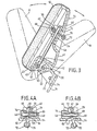
- Headrest 10 of the present invention is formed with a cushion 12 supported on a head support plate 14 which is pivotably attached to a chair mount 16.
- Chair mount 16 is formed with a shank portion 18 at one end thereof for engagement with the backrest of a dental chair and a pivot pin support 20 at the other end about which articulation of headrest 10 can occur.
- Pivot pin support 20 is formed with an upper section 22 and a lower section 24, having side walls 26 and 27 and a back wall 28.
- Section 22 of pivot pin support 20 is substantially "U"-shaped having a central opening 29 defined by the upper portions of side walls 26 and 27.
- Back wall 28 also has an opening therethrough which is coextensive with the opening defined by side walls 27 and 28.
- An opening 30 in side wall 26 and an opening 31 in side wall 27 are provided to rotatively receive a pivot pin 32 which is located in openings 33 and 34 in the side walls 39 and 40, respectively, of head support plate 14, and held therein by screws 35.
- Head support plate 14 is formed with a flange 36 extending about the periphery thereof to support cushion 12, which can be fastened thereto in a conventional manner.
- Head support plate 14 additionally has side walls 39 and 40, back wall 41 and bottom wall 42.
- An aperture 44 is provided through bottom wall 42 for passage therethrough of an elongated shaft 46, which is connected at or adjacent a first end 47 to a shaft pivot pin 50 by means of a threaded nut 51.
- Shaft pivot pin 50 is rotatively retained in pivot pin support 20 in holes 52 and 53. Shaft 46 thus is able to rotate forwardly an backwardly on pivot pin 50 with respect to pivot pin support 20.
- Back wall 41 of head support plate 41 is formed with a raised portion 54, on which are provided lugs 55 and 56 for attachment of lock plate pin support 58 and lock plate pin support 59 by means of attaching screws 61.
- Lock plate pin supports 58 and 59 are each provided with an aperture 60 extending through the sides thereof to rotatively receive lock plate pin 62.
- Lock plate pin 62 is formed with a flat surface 66 on its side which is nearest first end 47 of shaft 46.
- a lock plate 68 is fastened to flat surface 66 by means of attaching screws 69.
- Lock plate 68 extends through an aperture 71 formed in back wall 41 of head support plate 14.
- Spring 70 is provided to bias lock plate 68 in a direction toward first end 47 of shaft 46 and is formed with ends 78, which contact lugs 55 and 56, and an intermediate section 79 which urges lock plate 68 toward first end 47 of shaft 46.
- Release handle 72 is attached by means of attachment screws (not shown) to end 75 of lock plate 68 which extends outwardly through aperture 71 in back wall 41 of head support plate 14.
- a substantially cylindrical opening 74 is provided in lock plate 68 to receive second end 48 of shaft 46. Opening 74 is formed in lock plate 68 at an angle relative to the plane in which lock plate 68 lies.
- the central longitudinal axis of opening 74 parallel to inner surface 76 of opening 74 lies in the same vertical plane as the longitudinal axis of shaft 46.
- the angle a formed between the plane in which lock plate 68 lies and the longitudinal axis of opening 74 is typically between about 60°-80°, and an angle of 70° has been found to be satisfactory.
- Opening 74 optionally can have a relief cut on the lower semicircle of the front edge of opening 74 and a relief cut on the upper semicircle of the back edge of opening to define binding edges 82 and 83, respectively.
- the sharply defined edges 82 and 83 facilitate positive locking of lock plate 68 on shaft 46 when in the engaged position.
- headrest 10 is operable between a first position "A" in which bottom wall 42 of head support plate 14 abuts the top surface 23 of pivot pin support 20 and a second position "B" in which bottom wall 42 of head support plate 14 abuts back wall 28 of pivot pin support 20.
- lock plate 68 is biased by spring 70 toward a first position at which edges 82 and 83 engage the outer surface of shaft 46, as shown in FIG. 4A, to fixedly secure head support plate 14 and prevent the backward rotation thereof.
- shaft 46 pivots about pivot pin support 20 on shaft pivot pin 50 and slides over surface 76 as lock plate 68 moves axially along the length of shaft 46 toward the second end 48 thereof.
- spring 70 urges lock plate 68 in a direction toward first end 47 of shaft 46, thereby locating lock plate 68 in its first position and causing binding edges 82 and 83 of opening 74 to again engage the outer surface of shaft 46.
- This aspect of the invention is particularly important in installations where "sit-down" dentistry is practiced.
- the dental operator is positioned near the dental chair on a stool and operates the reclining chair while so positioned. It is possible during a lapse of attention on the operator's part, that the headrest come in contact with the leg or knee of the operator, pinning the operator between the headrest and the stool and causing injury. Such an occurrence is obviated when the headrest of the present invention is employed.
- pivot pin 32 is located on pivot pin support 20 such that it is positionable below the nape of the neck of a patient. As head support plate 14 moves from the extreme forward position to the extreme backward position, head support plate 14 and cushion 12 will always remain under and in contact with the head of the patient. Accordingly, there is no position assumable by the headrest, even during rapid movement thereof, which will not provide adequate support for the head of a patient, and possibilities of whiplash or other trauma experienced by the patient are effectively eliminated.
- the aforesaid location of pivot pin 32 permits the use of a cushion having a relatively small size so as not to interfere with the dental operator's access to the patient.
Landscapes
- Health & Medical Sciences (AREA)
- Oral & Maxillofacial Surgery (AREA)
- Life Sciences & Earth Sciences (AREA)
- Animal Behavior & Ethology (AREA)
- General Health & Medical Sciences (AREA)
- Public Health (AREA)
- Veterinary Medicine (AREA)
- Accommodation For Nursing Or Treatment Tables (AREA)
Claims (5)
Applications Claiming Priority (2)
| Application Number | Priority Date | Filing Date | Title |
|---|---|---|---|
| US83735 | 1979-10-10 | ||
| US06/083,735 US4312538A (en) | 1979-10-10 | 1979-10-10 | Articulating headrest |
Publications (2)
| Publication Number | Publication Date |
|---|---|
| EP0027419A1 EP0027419A1 (fr) | 1981-04-22 |
| EP0027419B1 true EP0027419B1 (fr) | 1984-07-18 |
Family
ID=22180345
Family Applications (1)
| Application Number | Title | Priority Date | Filing Date |
|---|---|---|---|
| EP80401452A Expired EP0027419B1 (fr) | 1979-10-10 | 1980-10-09 | Appuie-tête articulé pour siège de dentiste |
Country Status (4)
| Country | Link |
|---|---|
| US (1) | US4312538A (fr) |
| EP (1) | EP0027419B1 (fr) |
| CA (1) | CA1157763A (fr) |
| DE (1) | DE3068613D1 (fr) |
Cited By (1)
| Publication number | Priority date | Publication date | Assignee | Title |
|---|---|---|---|---|
| DE4410277A1 (de) * | 1994-03-24 | 1995-10-05 | Kaltenbach & Voigt | Ärztlicher oder zahnärztlicher Behandlungsstuhl |
Families Citing this family (13)
| Publication number | Priority date | Publication date | Assignee | Title |
|---|---|---|---|---|
| US5190349A (en) * | 1990-03-29 | 1993-03-02 | A-Dec, Inc. | Dental chair |
| US5378043A (en) * | 1993-06-01 | 1995-01-03 | General Motors Corporation | Vehicle pivotal headrest |
| USD347946S (en) | 1993-06-10 | 1994-06-21 | A-Dec, Inc. | Dental chair |
| USD357834S (en) | 1993-06-10 | 1995-05-02 | A-Dec, Inc. | Headrest |
| JP3221207B2 (ja) * | 1994-02-23 | 2001-10-22 | アイシン精機株式会社 | ヘツドレスト装置 |
| US5564668A (en) * | 1995-02-15 | 1996-10-15 | Crowe, Ii; Marvin E. | Computer stand for vehicles |
| US5678894A (en) * | 1996-04-08 | 1997-10-21 | Eley; Christopher D. | Dental chair with headrest |
| GB2313775A (en) * | 1996-06-08 | 1997-12-10 | Nash Kevin Tackle Ltd | Bed chair |
| US5964505A (en) * | 1996-09-24 | 1999-10-12 | Lear Corp. | Detachable cantilevered headrest having a ratchet mechanism |
| US7137668B2 (en) * | 2003-04-29 | 2006-11-21 | Intier Automotive Inc. | Multi-position head restraint |
| US7644987B2 (en) | 2004-09-27 | 2010-01-12 | Lear Corporation | Vehicle seat having active head restraint system |
| CN105534136B (zh) * | 2016-01-25 | 2018-09-11 | 东莞市伟宏五金塑胶制品有限公司 | 自动升降头枕架 |
| AU2021106490A4 (en) * | 2021-03-26 | 2021-11-04 | Modsel Pty Ltd | Headrest for surgical procedures |
Family Cites Families (11)
| Publication number | Priority date | Publication date | Assignee | Title |
|---|---|---|---|---|
| US1542508A (en) * | 1922-08-02 | 1925-06-16 | Koenigkramer Frederick | Chair |
| US1629306A (en) * | 1926-06-10 | 1927-05-17 | John J Reeder | Headrest for barber chairs |
| US1810134A (en) * | 1928-07-16 | 1931-06-16 | Emil J Paidar Co | Chiropodist chair |
| US2662585A (en) * | 1949-06-10 | 1953-12-15 | Doak Aircraft Company Inc | Seat with adjustable back rest |
| DE803554C (de) * | 1949-12-02 | 1951-04-05 | Herzog Karl Fa | Stuhl mit unter verschiedenen Neigungen feststellbarer Rueckenlehne |
| US2925854A (en) * | 1957-07-29 | 1960-02-23 | Modecraft Company Inc | Adjustable reclining couch |
| US3135550A (en) * | 1961-11-29 | 1964-06-02 | American Optical Corp | Adjustable chair for professional purposes |
| US3207549A (en) * | 1963-05-14 | 1965-09-21 | American Metal Products | Seat safety lock |
| US3817576A (en) * | 1972-10-02 | 1974-06-18 | Pennwalt Corp | Dental chair with adjustable headrest |
| DE2646613A1 (de) * | 1976-10-15 | 1978-04-20 | Ritter Ag | Kopfstuetze fuer dentalstuehle |
| DE7739993U1 (de) * | 1977-12-29 | 1978-04-06 | Recaro Gmbh & Co, 7312 Kirchheim | Kopfstuetze fuer fahrzeuge |
-
1979
- 1979-10-10 US US06/083,735 patent/US4312538A/en not_active Expired - Lifetime
-
1980
- 1980-10-09 EP EP80401452A patent/EP0027419B1/fr not_active Expired
- 1980-10-09 CA CA000362049A patent/CA1157763A/fr not_active Expired
- 1980-10-09 DE DE8080401452T patent/DE3068613D1/de not_active Expired
Cited By (1)
| Publication number | Priority date | Publication date | Assignee | Title |
|---|---|---|---|---|
| DE4410277A1 (de) * | 1994-03-24 | 1995-10-05 | Kaltenbach & Voigt | Ärztlicher oder zahnärztlicher Behandlungsstuhl |
Also Published As
| Publication number | Publication date |
|---|---|
| CA1157763A (fr) | 1983-11-29 |
| US4312538A (en) | 1982-01-26 |
| DE3068613D1 (en) | 1984-08-23 |
| EP0027419A1 (fr) | 1981-04-22 |
Similar Documents
| Publication | Publication Date | Title |
|---|---|---|
| EP0027419B1 (fr) | Appuie-tête articulé pour siège de dentiste | |
| US5765914A (en) | Chair with a tilt control mechanism | |
| US6139103A (en) | Synchronized chair seat and backrest tilt control mechanism | |
| CA2239365C (fr) | Appuie-bras a reglages multiples | |
| CN100548183C (zh) | 人体工程学座椅臂 | |
| US7497512B2 (en) | Recliner drive mechanism for a rocker chair | |
| CA2055373C (fr) | Dispositif servant de repose-jambes extensible et pouvant etre pose en rattrapage | |
| US5195770A (en) | Reclining mechanism for baby carriage | |
| US6997510B2 (en) | Rocking chair with automatic locking mechanism | |
| US4844536A (en) | Extensible legrest mechanism for furniture seating units | |
| JP2003079481A (ja) | 椅 子 | |
| CN108248461A (zh) | 一种座椅调节装置及一种座椅 | |
| US3272555A (en) | Adjustable back lounge chair | |
| US6079787A (en) | Armrest mechanism for dental chairs | |
| US4014594A (en) | Headrest for operatory chair | |
| US4506926A (en) | Reclining chair with push-button actuator mechanism | |
| US7152927B1 (en) | Ratcheted headrest for a recliner chair | |
| WO1998004171A1 (fr) | Mecanisme d'accoudoir pour fauteuils dentaires | |
| KR200292593Y1 (ko) | 의자용 팔걸이 | |
| JP2018175210A (ja) | 椅子 | |
| JPS6313942Y2 (fr) | ||
| CN223590604U (zh) | 一种可多角度调节的头枕支架和汽车头枕 | |
| CN117922399B (zh) | 一种儿童汽车安全座椅 | |
| JP7521923B2 (ja) | 椅子 | |
| JP7547070B2 (ja) | 椅子 |
Legal Events
| Date | Code | Title | Description |
|---|---|---|---|
| PUAI | Public reference made under article 153(3) epc to a published international application that has entered the european phase |
Free format text: ORIGINAL CODE: 0009012 |
|
| AK | Designated contracting states |
Designated state(s): BE DE FR GB IT LU NL SE |
|
| 17P | Request for examination filed |
Effective date: 19811008 |
|
| ITF | It: translation for a ep patent filed | ||
| GRAA | (expected) grant |
Free format text: ORIGINAL CODE: 0009210 |
|
| AK | Designated contracting states |
Designated state(s): BE DE FR GB IT LU NL SE |
|
| REF | Corresponds to: |
Ref document number: 3068613 Country of ref document: DE Date of ref document: 19840823 |
|
| ET | Fr: translation filed | ||
| PGFP | Annual fee paid to national office [announced via postgrant information from national office to epo] |
Ref country code: SE Payment date: 19840930 Year of fee payment: 5 Ref country code: BE Payment date: 19840930 Year of fee payment: 5 |
|
| PG25 | Lapsed in a contracting state [announced via postgrant information from national office to epo] |
Ref country code: LU Free format text: LAPSE BECAUSE OF NON-PAYMENT OF DUE FEES Effective date: 19841031 |
|
| PLBE | No opposition filed within time limit |
Free format text: ORIGINAL CODE: 0009261 |
|
| STAA | Information on the status of an ep patent application or granted ep patent |
Free format text: STATUS: NO OPPOSITION FILED WITHIN TIME LIMIT |
|
| 26N | No opposition filed | ||
| PG25 | Lapsed in a contracting state [announced via postgrant information from national office to epo] |
Ref country code: SE Effective date: 19871010 |
|
| PGFP | Annual fee paid to national office [announced via postgrant information from national office to epo] |
Ref country code: NL Payment date: 19871031 Year of fee payment: 8 |
|
| PG25 | Lapsed in a contracting state [announced via postgrant information from national office to epo] |
Ref country code: BE Effective date: 19881031 |
|
| BERE | Be: lapsed |
Owner name: SYNTEX (U.S.A.) INC. Effective date: 19881031 |
|
| PG25 | Lapsed in a contracting state [announced via postgrant information from national office to epo] |
Ref country code: NL Effective date: 19890501 |
|
| NLV4 | Nl: lapsed or anulled due to non-payment of the annual fee | ||
| PGFP | Annual fee paid to national office [announced via postgrant information from national office to epo] |
Ref country code: FR Payment date: 19900830 Year of fee payment: 11 |
|
| PGFP | Annual fee paid to national office [announced via postgrant information from national office to epo] |
Ref country code: GB Payment date: 19900906 Year of fee payment: 11 |
|
| ITTA | It: last paid annual fee | ||
| PGFP | Annual fee paid to national office [announced via postgrant information from national office to epo] |
Ref country code: DE Payment date: 19901126 Year of fee payment: 11 |
|
| PG25 | Lapsed in a contracting state [announced via postgrant information from national office to epo] |
Ref country code: GB Effective date: 19911009 |
|
| GBPC | Gb: european patent ceased through non-payment of renewal fee | ||
| PG25 | Lapsed in a contracting state [announced via postgrant information from national office to epo] |
Ref country code: FR Effective date: 19920630 |
|
| PG25 | Lapsed in a contracting state [announced via postgrant information from national office to epo] |
Ref country code: DE Effective date: 19920701 |
|
| REG | Reference to a national code |
Ref country code: FR Ref legal event code: ST |
|
| EUG | Se: european patent has lapsed |
Ref document number: 80401452.0 Effective date: 19880707 |