EP0027433B1 - Dispositif de transfert de pièces, notamment des clés en métal d'une première station d'alimentation vers une station de traitement et de déchargement placée angulairement par rapport à la précédente et inversement - Google Patents
Dispositif de transfert de pièces, notamment des clés en métal d'une première station d'alimentation vers une station de traitement et de déchargement placée angulairement par rapport à la précédente et inversement Download PDFInfo
- Publication number
- EP0027433B1 EP0027433B1 EP80830079A EP80830079A EP0027433B1 EP 0027433 B1 EP0027433 B1 EP 0027433B1 EP 80830079 A EP80830079 A EP 80830079A EP 80830079 A EP80830079 A EP 80830079A EP 0027433 B1 EP0027433 B1 EP 0027433B1
- Authority
- EP
- European Patent Office
- Prior art keywords
- station
- carriage
- rotation
- operating
- key
- Prior art date
- Legal status (The legal status is an assumption and is not a legal conclusion. Google has not performed a legal analysis and makes no representation as to the accuracy of the status listed.)
- Expired
Links
- 239000002184 metal Substances 0.000 title claims abstract description 5
- 238000006073 displacement reaction Methods 0.000 claims description 6
- 210000001364 upper extremity Anatomy 0.000 claims description 5
- 210000003414 extremity Anatomy 0.000 claims description 4
- 210000003141 lower extremity Anatomy 0.000 claims description 2
- 230000000694 effects Effects 0.000 abstract description 3
- 238000003754 machining Methods 0.000 description 4
- 230000000295 complement effect Effects 0.000 description 1
- 230000007423 decrease Effects 0.000 description 1
- 230000003068 static effect Effects 0.000 description 1
- 230000002459 sustained effect Effects 0.000 description 1
- 238000011144 upstream manufacturing Methods 0.000 description 1
Images


Classifications
-
- B—PERFORMING OPERATIONS; TRANSPORTING
- B23—MACHINE TOOLS; METAL-WORKING NOT OTHERWISE PROVIDED FOR
- B23Q—DETAILS, COMPONENTS, OR ACCESSORIES FOR MACHINE TOOLS, e.g. ARRANGEMENTS FOR COPYING OR CONTROLLING; MACHINE TOOLS IN GENERAL CHARACTERISED BY THE CONSTRUCTION OF PARTICULAR DETAILS OR COMPONENTS; COMBINATIONS OR ASSOCIATIONS OF METAL-WORKING MACHINES, NOT DIRECTED TO A PARTICULAR RESULT
- B23Q7/00—Arrangements for handling work specially combined with or arranged in, or specially adapted for use in connection with, machine tools, e.g. for conveying, loading, positioning, discharging, sorting
- B23Q7/04—Arrangements for handling work specially combined with or arranged in, or specially adapted for use in connection with, machine tools, e.g. for conveying, loading, positioning, discharging, sorting by means of grippers
-
- B—PERFORMING OPERATIONS; TRANSPORTING
- B23—MACHINE TOOLS; METAL-WORKING NOT OTHERWISE PROVIDED FOR
- B23C—MILLING
- B23C3/00—Milling particular work; Special milling operations; Machines therefor
- B23C3/28—Grooving workpieces
- B23C3/35—Milling grooves in keys
-
- B—PERFORMING OPERATIONS; TRANSPORTING
- B23—MACHINE TOOLS; METAL-WORKING NOT OTHERWISE PROVIDED FOR
- B23Q—DETAILS, COMPONENTS, OR ACCESSORIES FOR MACHINE TOOLS, e.g. ARRANGEMENTS FOR COPYING OR CONTROLLING; MACHINE TOOLS IN GENERAL CHARACTERISED BY THE CONSTRUCTION OF PARTICULAR DETAILS OR COMPONENTS; COMBINATIONS OR ASSOCIATIONS OF METAL-WORKING MACHINES, NOT DIRECTED TO A PARTICULAR RESULT
- B23Q1/00—Members which are comprised in the general build-up of a form of machine, particularly relatively large fixed members
- B23Q1/25—Movable or adjustable work or tool supports
- B23Q1/44—Movable or adjustable work or tool supports using particular mechanisms
- B23Q1/50—Movable or adjustable work or tool supports using particular mechanisms with rotating pairs only, the rotating pairs being the first two elements of the mechanism
- B23Q1/52—Movable or adjustable work or tool supports using particular mechanisms with rotating pairs only, the rotating pairs being the first two elements of the mechanism a single rotating pair
Definitions
- the invention relates to a device for transferring pieces, in particular metal keys, from a first infeed station to a second operating and discharge station placed angularly with respect to the former, and vice versa.
- suction- grippipng means supported by a transfer arm which moves through an angle of 90°.
- Said arm is mounted on a vertical shaft supported by a column member and connected, by a crank arm and a cam follower roller, to a cam driven in motion by a motorized shaft, provided to rotate said vertical shaft in successive time in clockwise and in anticlockwise direction.
- the device object of the present invention comprises a turret, supported by a frame, and comprises a tubular member able to rotate about an axis perpendicular to the transfer plane of the said keys, inside which tubular member is located a shaft, rotatable by an operating system, and to the upper extremity of which is keyed a gear wheel that meshes with a slidable rack; a carriage, connected to the rack and movable along a longitudinal support guide integral with the said tubular member and on which are integrally located buffer elements that define the travel limits for the rack, the said carriage being movable between two extreme positions, corresponding to the travel limits of the rack, namely, a position of maximum radial retraction in which in use a clamping device, placed on the radially outward extremity of the said carriage, withdraws the said key from the said infeed station, and a position of maximum radial advancement in which in use the said key is transferred into the region of the said operating and discharge station, at which station the said carriage in use again
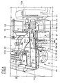
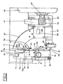
- the device in question comprises a turret (1), supported by the frame (2) through a flange (3), comprising a tubular member (4) able to rotate around an axis (A) perpendicular to the transfer plane of each key (5).
- a shaft (6) Inside the tubular member (4) is placed a shaft (6), carried in rotation by an operating system (7), that exerts an effect on a pinion (8) keyed along the lower extremity of the said shaft (6).
- the lower part of the tubular member (4) is supported by means of a bush (9), and the upper part by a thrust bearing (9a) sustained by the flange (3).
- the upper extremity of the shaft (6) had keyed to it a gear wheel (10) that meshes with a rack (11) connected integrally, by means of a pin (12), to a carriage (13) overhead, movable along a longitudinal support guide (14) which is nothing more than an upper extension to the tubular member (4).
- the rack (11) is able to slide inside the longitudinal support (14) in which are also positioned the buffer elements (15) and (16) provided to define the travel limits for the rack (11) pertinent to the position of maximum retraction and maximum advancement, respectively, of the carriage (13).
- the said carriage (13) is provided with a clamping device (17), placed on the front extremity thereof, constituted by a stationary gripper (17a) and by a movable gripper (17b), able to rotate around the fulcrum (18) in such a way as to determine the clamping or the release or the key (5).
- the said grippers extend essentially along planes coincident with the transfer plane of the key (5) so that the clamping is effected on the lateral borders of the said key (5).
- the rotation of the movable gripper (17b) takes place through a rocker arm (19), pivotally connected to the upper border (20) of the longitudinal support (14), making pressing contact with the said gripper (17b), on one side or the other with respect to the fulcrum (18), depending on whether the key (5) is to be clamped or released.
- the rocker arm (19) is subjected to the action of a spring (21) placed in the region of the extremity of the lower stem (19a) of the rocker arm (19), reacting with a force directed towards the outside of the vertical border of the support (14) in such a way that, in the static position, the rocker arm (19) maintains the movable gripper (17b) in the clamping position.
- a spring (21) placed in the region of the extremity of the lower stem (19a) of the rocker arm (19) of the rocker arm (19)
- a force directed towards the outside of the vertical border of the support (14) in such a way that, in the static position, the rocker arm (19) maintains the movable gripper (17b) in the clamping position.
- the clamping device (17), constituted in this way, thus follows all the displacements of the carriage (13), movable between the said position of maximum retraction, in which the clamping device (17) withdraws the key (5) from an infeed station (25), and the said position of maximum advancement, in which the key (5) is transferred to an operating and discharge station (26), during which the carriage (13) again adopts the said position of maximum retraction in order to send the key (5) to an expulsion chute (27) via a hole (28) placed immediately upstream with respect to a machining tool (29).
- the operating station (26) is placed angularly with respect to the infeed station (25), and exactly at a right angle therewith.
- the said key could, because of the constitution of the clamping device ( 17), free itself therefrom, and thus provision has been made, in the region of the said stations, for corresponding support platforms (30) and (31) for the key (5), while along the arc of a circle defined by the transfer path of the clamping device (17), a platform (32), constructed in the form of a sector, is provided.
- tubular member (4) is subjected to the action of an elastic device, in the case in question constituted by a spring (33), connected at one extremity to the frame (2) and at the other to the said tubular member (4), via a ring (34) integrally connected to the member (4).
- an elastic device in the case in question constituted by a spring (33), connected at one extremity to the frame (2) and at the other to the said tubular member (4), via a ring (34) integrally connected to the member (4).
- the inclusion of the spring (33) is absolutely vital since it supplies the support (14) with sufficient torque to allow it one complete rotation from the station (25) to the station (26) in harmony with, and at the same time as, the rotation, in the same direction, of the gear wheel (10) whose angle of complete rotation, in one of the two directions, determined by the operating system (7), is identical to the sum of the angle of rotation required for the support (14) to be carried form one of the said stations to the other, and of the angle of rotation required for the carriage (13) to be carried from one of the said extreme positions to the other.
- the support (14) rotates from the station (26) to the station (25)
- the spring loads and vice versa its torsional force only comes functionally into play when the support (14) has to rotate from the station (25) to the station (26).
- the operating system is constituted by a sector gear (35) that is pivoted at (36) to the frame (2) and meshes with the pinion (8).
- the lower part of the sector gear (35) has an extension (37) in which is engaged the shank (38) of a roller (39) that lies on a plane parallel to that on which the sector gear (35) lies.
- the roller (39) slides on the profile (40) of a cam (41) of the rotating disc type that lies on a plane perpendicular to that on which the sector gear (35) lies.
- a buffer element (42) placed on the righthand side of the turret (1) and there to define a limit in the rotation of the support (14) in the two directions, this being through a first buffer (43) placed on the inside front of the said element (42), and a second buffer (44), constituted by the outside lateral flank of the said element (42), with which a screw projection (45) placed on the side of the support (14) comes into contact.
- the device forming the subject of the invention is utilized to transfer previously milled keys of the type (5) to said operating station (26) where what is called the "backing" operation is carried out on the key.
- the said operation consists in rounding off the back (46) of the key (5) in a way complementary to the outside circumference of the barrel of the lock to which the key is destined.
- the operating station (26) is provided with a tool (29), in this particular instance a rotating cutter, which is keyed to a shaft (47) that describes an arc of a circle whose radius is that required for the backing.
- a tool (29) in this particular instance a rotating cutter, which is keyed to a shaft (47) that describes an arc of a circle whose radius is that required for the backing.
- the said clamping device (17) is controlled by the operating means (22) and (23), the former being placed in proximity of the transfer plane of the key (5), in the region of the infeed station (25), while the latter is placed, for example, above the buffer element (42).
- the stem (19b), opposite the stem (19a) of the rocker arm (19) is provided on its lower part with a tab (19b').
- the operating means (22) are, in fact, constituted simply by a pin (22a) integral with the frame (2) and positioned at a height almost up to the said transfer plane, provided to locate the tab (196') before the support (14) has reached the vertical position (Fig. 2).
- the operating means (23) are, instead, constituted by a common pneumatic piston that makes pressing contact transversely along the stem (19a) (Fig. 1).
- a micro proximity switch (50) placed beneath the sector gear (35) and provided to take the device out of operation.
- the said micro switch (50) is tripped by the displacement of the stem (51) of a wedge shaped member (52) inserted elastically in a hole made in a small carriage (53), in the inside of which is engaged the shank (38) of the roller (39), able to slide vertically with respect to the profile (40) of the cam (41) in the event of the rotation of the support (14) being in some way impeded during the rotation of the sector gear (35).
- the gear wheel (10) has also rotated at a right angle.
- the rack (11) starts to be displaced until it arrives in contact with the buffer element (16) and this determines the forward movement of the carriage (13) which is thus passed from the position of maximum retraction to that of maximum advancement.
- the sector gear (35) halts and the operation of "backing" the key (5) commences; once this has ended, the cam (41) places anew the sector gear (35) in rotation in a clockwise direction, that is to say, in the reverse direction to that in which it was rotated previously.
- the spring (33), now not loaded, does not in any way influence the support (14) and thus the anti-clockwise rotation of the gear wheel (10) initially carries in movement only the rack (11), until the carriage (13) has returned to its position of maximum retraction.
- the rack (11) comes into contact with the buffer element (1 5), with the anti-clockwise rotation of the gear wheel (10) continuing and since the buffer element (15) is integral with the support (14), a torque is created, with respect to the axis (A), defined by the product of the force aplied to the crown gear (1 Oa) of the gear wheel (10) because of the radius thereof, which brings about the rotation of the support (14) in the said anti-clockwise direction up until the rotation of the gear wheel (10) ceases, when the support (14) comes into contact, through the screw projection (45), with the buffer element (44).
- the sector gear (35) halts and a fresh cycle is commenced.
- the profile (40) of the cam (41) is so shaped that during the continuous rotation of the latter, the sector gear (35) undergoes alternate rotations and pauses until the rotation has been completed in one direction or the other.
- the phases of rotation of the support (14) and of displacement of the rack (11) (and thus of the carriage (13)) are shown in Figs. 4, 5, 6, 7, 8 and 9.
- the support (14) is shown diagrammatically in Fig. 4 in the horizontal working position with the carriage in the position of maximum advancement at the moment when the carriage (13) starts to move backwards.
- the contact area between the gear wheel (10) and the rack (11) has been shown as (x).
- Fig. 5 during the rotation of the gear wheel (10) in the anti-clockwise direction (SA), the point (x) is carried to a position corresponding to the maximum retraction of the carriage (13), and in the said situation the contact area between the gear wheel (10) and the rack (11) has been shown as (y) .
Landscapes
- Engineering & Computer Science (AREA)
- Mechanical Engineering (AREA)
- Specific Conveyance Elements (AREA)
- Turning (AREA)
- Domestic Plumbing Installations (AREA)
- Accessory Devices And Overall Control Thereof (AREA)
- Forging (AREA)
- Preliminary Treatment Of Fibers (AREA)
Claims (5)
Priority Applications (1)
| Application Number | Priority Date | Filing Date | Title |
|---|---|---|---|
| AT80830079T ATE4178T1 (de) | 1979-10-10 | 1980-10-08 | Transfervorrichtung fuer werkstuecke, insbesondere fuer metallene schluessel, von einer ersten einlegestation zu einer zweiten bearbeitungs- und ausnahmestation mit einer eckigen aufstellung in bezug auf die vorhergehende station, und umgekehrt. |
Applications Claiming Priority (2)
| Application Number | Priority Date | Filing Date | Title |
|---|---|---|---|
| IT350279 | 1979-10-10 | ||
| IT03502/79A IT1165868B (it) | 1979-10-10 | 1979-10-10 | Dispositivo di trasferimento di pezzi in particolare chiavi metalli che da una prima stazione di alimentazione ad una seconda stazione operativa e di scarisco disposta angolarmente alla prima e viceversa |
Publications (2)
| Publication Number | Publication Date |
|---|---|
| EP0027433A1 EP0027433A1 (fr) | 1981-04-22 |
| EP0027433B1 true EP0027433B1 (fr) | 1983-07-20 |
Family
ID=11108573
Family Applications (1)
| Application Number | Title | Priority Date | Filing Date |
|---|---|---|---|
| EP80830079A Expired EP0027433B1 (fr) | 1979-10-10 | 1980-10-08 | Dispositif de transfert de pièces, notamment des clés en métal d'une première station d'alimentation vers une station de traitement et de déchargement placée angulairement par rapport à la précédente et inversement |
Country Status (4)
| Country | Link |
|---|---|
| EP (1) | EP0027433B1 (fr) |
| AT (1) | ATE4178T1 (fr) |
| DE (1) | DE3064306D1 (fr) |
| IT (1) | IT1165868B (fr) |
Families Citing this family (1)
| Publication number | Priority date | Publication date | Assignee | Title |
|---|---|---|---|---|
| ITRE20050017A1 (it) * | 2005-03-04 | 2006-09-05 | A C S S R L | Sistema di manipolazione delle chiavi per macchina cifratrice |
Family Cites Families (6)
| Publication number | Priority date | Publication date | Assignee | Title |
|---|---|---|---|---|
| US1993754A (en) * | 1931-11-23 | 1935-03-12 | Seneca Falls Machine Co | Work feeding mechanism for machine tools |
| BE388086A (fr) * | 1932-04-25 | |||
| US3080840A (en) * | 1960-03-17 | 1963-03-12 | Gen Motors Corp | Press transfer mechanism |
| US3116665A (en) * | 1961-12-28 | 1964-01-07 | Osco Corp | Key duplicating machine |
| US3189193A (en) * | 1963-06-12 | 1965-06-15 | Westinghouse Electric Corp | Article transfer machine |
| DE2630858C3 (de) * | 1976-07-09 | 1986-07-31 | Volkswagen AG, 3180 Wolfsburg | Transportautomat |
-
1979
- 1979-10-10 IT IT03502/79A patent/IT1165868B/it active
-
1980
- 1980-10-08 AT AT80830079T patent/ATE4178T1/de not_active IP Right Cessation
- 1980-10-08 DE DE8080830079T patent/DE3064306D1/de not_active Expired
- 1980-10-08 EP EP80830079A patent/EP0027433B1/fr not_active Expired
Also Published As
| Publication number | Publication date |
|---|---|
| ATE4178T1 (de) | 1983-08-15 |
| IT7903502A0 (it) | 1979-10-10 |
| DE3064306D1 (en) | 1983-08-25 |
| IT1165868B (it) | 1987-04-29 |
| EP0027433A1 (fr) | 1981-04-22 |
Similar Documents
| Publication | Publication Date | Title |
|---|---|---|
| US3028020A (en) | Automatic device for feeding workpieces to machine-tools | |
| JPS5845836A (ja) | 工作機械の工具交換装置 | |
| GB1320252A (en) | Forging machine | |
| US2736238A (en) | moncrieff | |
| US4575918A (en) | Tool change mechanism | |
| US3659486A (en) | High speed trim machine for blown plastic articles | |
| US2542986A (en) | Machine tool | |
| US2906177A (en) | Gear finishing | |
| EP0027433A1 (fr) | Dispositif de transfert de pièces, notamment des clés en métal d'une première station d'alimentation vers une station de traitement et de déchargement placée angulairement par rapport à la précédente et inversement | |
| US2777520A (en) | Machine for cutting off lengths of tubing | |
| US3820234A (en) | Machining center with automatic tool changer | |
| US2059710A (en) | Automatic metalworking machine | |
| US3200472A (en) | Automatically chucking multiple spindle machine tool | |
| GB1062549A (en) | Turbine blade milling apparatus | |
| GB1469788A (en) | Manipulation arm | |
| US3276301A (en) | Cut off machine for cutting elongated stock into blanks | |
| JP3517132B2 (ja) | 圧造機におけるワークの飛び出し防止及び押し込み装置 | |
| JP3612415B2 (ja) | 自動工具交換式加工装置 | |
| JPH01115539A (ja) | 自動工具交換装置 | |
| GB1355395A (en) | Loading device for machine tools | |
| JPS60185Y2 (ja) | 工作物位相決め装置 | |
| SU1007907A1 (ru) | Устройство автоматической смены инструмента | |
| US3187908A (en) | Workpiece head working machine | |
| JPH0314248Y2 (fr) | ||
| JP2542841B2 (ja) | 工作機械 |
Legal Events
| Date | Code | Title | Description |
|---|---|---|---|
| PUAI | Public reference made under article 153(3) epc to a published international application that has entered the european phase |
Free format text: ORIGINAL CODE: 0009012 |
|
| AK | Designated contracting states |
Designated state(s): AT BE DE FR GB NL |
|
| 17P | Request for examination filed |
Effective date: 19810720 |
|
| GRAA | (expected) grant |
Free format text: ORIGINAL CODE: 0009210 |
|
| AK | Designated contracting states |
Designated state(s): AT BE DE FR GB NL |
|
| PG25 | Lapsed in a contracting state [announced via postgrant information from national office to epo] |
Ref country code: NL Effective date: 19830720 Ref country code: FR Free format text: THE PATENT HAS BEEN ANNULLED BY A DECISION OF A NATIONAL AUTHORITY Effective date: 19830720 Ref country code: BE Effective date: 19830720 |
|
| REF | Corresponds to: |
Ref document number: 4178 Country of ref document: AT Date of ref document: 19830815 Kind code of ref document: T |
|
| PG25 | Lapsed in a contracting state [announced via postgrant information from national office to epo] |
Ref country code: AT Effective date: 19830801 |
|
| REF | Corresponds to: |
Ref document number: 3064306 Country of ref document: DE Date of ref document: 19830825 |
|
| NLV1 | Nl: lapsed or annulled due to failure to fulfill the requirements of art. 29p and 29m of the patents act | ||
| EN | Fr: translation not filed | ||
| PLBE | No opposition filed within time limit |
Free format text: ORIGINAL CODE: 0009261 |
|
| STAA | Information on the status of an ep patent application or granted ep patent |
Free format text: STATUS: NO OPPOSITION FILED WITHIN TIME LIMIT |
|
| 26N | No opposition filed | ||
| GBPC | Gb: european patent ceased through non-payment of renewal fee | ||
| PG25 | Lapsed in a contracting state [announced via postgrant information from national office to epo] |
Ref country code: GB Effective date: 19881118 |
|
| PGFP | Annual fee paid to national office [announced via postgrant information from national office to epo] |
Ref country code: DE Payment date: 19901130 Year of fee payment: 11 |
|
| PG25 | Lapsed in a contracting state [announced via postgrant information from national office to epo] |
Ref country code: DE Effective date: 19920701 |