EP0027572A1 - Procédé et dispositif pour la transmission chiffrée d'une information - Google Patents
Procédé et dispositif pour la transmission chiffrée d'une information Download PDFInfo
- Publication number
- EP0027572A1 EP0027572A1 EP80105886A EP80105886A EP0027572A1 EP 0027572 A1 EP0027572 A1 EP 0027572A1 EP 80105886 A EP80105886 A EP 80105886A EP 80105886 A EP80105886 A EP 80105886A EP 0027572 A1 EP0027572 A1 EP 0027572A1
- Authority
- EP
- European Patent Office
- Prior art keywords
- information
- signal blocks
- blocks
- information signal
- substitution
- Prior art date
- Legal status (The legal status is an assumption and is not a legal conclusion. Google has not performed a legal analysis and makes no representation as to the accuracy of the status listed.)
- Withdrawn
Links
- 230000005540 biological transmission Effects 0.000 title claims abstract description 29
- 238000000034 method Methods 0.000 title claims description 14
- 238000006467 substitution reaction Methods 0.000 claims abstract description 53
- 238000001514 detection method Methods 0.000 claims 3
- 108010076504 Protein Sorting Signals Proteins 0.000 abstract description 11
- 238000001208 nuclear magnetic resonance pulse sequence Methods 0.000 description 3
- 230000000875 corresponding effect Effects 0.000 description 2
- 238000010586 diagram Methods 0.000 description 2
- 230000000712 assembly Effects 0.000 description 1
- 238000000429 assembly Methods 0.000 description 1
- 238000010276 construction Methods 0.000 description 1
- 230000002596 correlated effect Effects 0.000 description 1
- 230000000694 effects Effects 0.000 description 1
- 230000010365 information processing Effects 0.000 description 1
- 230000001681 protective effect Effects 0.000 description 1
Images
Classifications
-
- H—ELECTRICITY
- H04—ELECTRIC COMMUNICATION TECHNIQUE
- H04K—SECRET COMMUNICATION; JAMMING OF COMMUNICATION
- H04K1/00—Secret communication
- H04K1/06—Secret communication by transmitting the information or elements thereof at unnatural speeds or in jumbled order or backwards
-
- H—ELECTRICITY
- H04—ELECTRIC COMMUNICATION TECHNIQUE
- H04N—PICTORIAL COMMUNICATION, e.g. TELEVISION
- H04N1/00—Scanning, transmission or reproduction of documents or the like, e.g. facsimile transmission; Details thereof
- H04N1/44—Secrecy systems
- H04N1/448—Rendering the image unintelligible, e.g. scrambling
- H04N1/4486—Rendering the image unintelligible, e.g. scrambling using digital data encryption
Definitions
- the present invention relates to a method and a device for encrypted transmission of information according to the preamble of claim 1 and claim 4.
- the pulse stream to be processed is structured, i.e. packets are formed which are generally of the same length and thus comprise an equal number of pulses.
- the individual packets which are called “characters” in the telegraph language and “words” in the computer language, can be separated from one another by clock signals which serve as reference signals for the synchronization control on the receiving side.
- substituted or encryption message to be transmitted to either the individual packets as a whole can be permuted (letter or block encryption) or the sign ENEL elements individually encryption can be subjected to (B it-- or character element encryption).
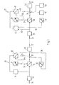
- a transmitting station 20 is connected to a receiving station 21 via a transmission link 22.
- the message transmission from the transmitting station 20 to the receiving station 21 can take place in a suitable, known manner, either wired or wireless.
- the transmitting station 20 has an input stage 23, the input of which is connected to a feed line 24 for the information to be processed and transmitted.
- the input stage 23 is followed by a memory 25, which consists of two memory halves B1, B2 (FIG. 2).
- This memory 25 is connected on the input side to a key generator 27 via an address line 26.
- the structure and mode of operation of this key generator 27, which generates the key information for encryption, is known.
- the memory 25 is connected via a changeover switch 28 to an output stage 29 to which the transmission link 22 is connected.
- a subscription signal generator (auxiliary key generator) 30 Connected to the second pole of the changeover switch 28 is a subscription signal generator (auxiliary key generator) 30 which, as will be explained below, generates subscription signals.
- This substitution signal generator 30 is also of a known type.
- a detector 31 is also connected to the output of the input stage 23 and is followed by a memory control circuit 32.
- Another input of this memory control circuit 32 is connected to the output of the key generator 27 via an address line 26a.
- These Memory control circuit 32 controls the changeover switch 28 via a control line 33.
- this memory control circuit 32 is also connected via a further control line 34 to the substitution signal generator 30 in order to control it.
- the receiving station 21 is provided with an input stage 35 connected to the transmission link 22, which is followed by a memory 36 with two memory halves.
- the structure of this memory 36 corresponds to the memory 25 of the transmitting station 20.
- the memory 36 is further connected via an address line 37 to a key generator 38 of a known type, which generates the decryption information necessary for decryption.
- this key generator 33 runs synchronously with the key generator 27 on the transmission side.
- the output of the memory 36 is connected to the one pole of a changeover switch 39 which is connected to an output stage 40.
- This output stage 40 is connected to a message sink via a connecting line 41.
- Two information signal generators 42, 43 of known construction are connected to further poles of the changeover switch 39 and generate information signals in a manner to be described.
- the output of the input stage 35 is further connected via a feed line 45 to the one input of a correlator 44, the second input of which is connected via a connecting line 46 to a comparison signal generator (auxiliary key generator) 47.
- This comparison signal generator 47 is constructed in the same way as the transmission-side substitution signal generator 30 and runs synchronously with it.
- the comparison signal generator 47 thus generates the same sequence of signals as the substitution signal generator 30.
- a memory control circuit 48 is connected downstream of the correlator 44, which on the input side which is connected to the output of the key generator 38 via an address line 37a.
- the memory control circuit 48 controls the changeover switch 39 via a control line 49 in a manner to be described below.
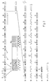
- FIG. 2A shows the pulse stream supplied by a message source, not shown, via the feed line 24 to the transmitting station 20.
- This is formed by information signal blocks 1 - 12 of equal length, which are separated from one another by separators (not shown).
- Each Informationssi g nalblock 1-12 consists of five signals that either "0" signals (light squares) or "L" - signals (dark squares) are.
- the information signal blocks 1 - 12 arriving one after the other in time are stored in the memory 25 via the input stage 23.
- this memory 25 consists of two memory halves B1 and B2.
- the incoming signal blocks 1 - 12 are first stored in order in the first half of the memory B1.
- each memory half B1, B2 allows ten information signal blocks to be stored.
- the reading of the individual information signal blocks from the first memory half Bl now begins, as indicated at C in FIG. 2.
- 2D shows a possible sequence of the information signal blocks as it can appear at the output of the memory 25. 2D, it is now readily apparent that the ten information signal blocks 1-10 appear in a sequence permuted compared to the original sequence shown in FIG. 2A.
- the second half of the memory B2 is filled, the first half of the memory B1 is emptied and ready for storing new information signal blocks.
- the individual information signal blocks are read out in a corresponding manner from the memory half B2 in a changed time sequence given by the key information.
- the permuted sequence of the information signal blocks generated in the transmitting station 20, as mentioned, is transmitted to the receiving station 21.
- the reception-side input stage 35 now ensures that the received information signal groups are stored in blocks in the memory 36.
- the latter like the transmission-side memory 25, has two memory halves which are alternately filled and read out as described with reference to the transmission-side storage.
- the received information signal blocks are not stored in the incoming chronological order, but in the chronological order originally supplied to the input stage 23 of the transmitting station 20, as shown in FIG. 2A.
- the key generator 38 which, as already mentioned, runs synchronously with the transmitter-side key generator 27, ensures this storing in the original order. This means that in the first Half of the memory 36, the information signal blocks 1-10 are stored as shown in FIG. 2 at B1. Decryption has thus been achieved by storing the information signal blocks in the original order under the influence of the key generator 38.
- the output stage 40 the Informationssi g nalblö c ke are supplied to a message sink, via the connecting line 41st
- the transmitter-side detector 31 is used to recognize the information signal blocks to be replaced. This detects those information signal blocks 4, 6, 10 which consist of similar signals. The detector 31 supplies the information as to which blocks are to be substituted to the memory control circuit 32, which also receives the information via the address line 26a as to where these blocks are stored in the memory 25. The status of each information signal block ("to be replaced" or "not to be replaced") stored in the memory 25 can now be queried from this memory control circuit 32.
- the key generator now calls, as has already been mentioned 27 according to the key information generated by him from the signal blocks from the different storage locations.
- the retrieved information signal blocks are fed to the output stage 29 via the changeover switch 28 normally applied to the output of the memory 25.
- a space that a block to be replaced comprises (ie memory locations 4, 6 and 10 in the memory half Bl)
- the memory control circuit 32 the yes dress line via the A 26a is actuated by the key generator 27, a control signal, which causes the switch 28 to be switched over to the output of the substitution signal generator 30 via the control line 33.
- substitution signal generator 30 has a higher clock rate than the key generator 27, since the latter only has to provide new information for each information signal block, while the substitution signal generator 30 has to deliver a quasi-random signal within a block that corresponds to the pulse rate if possible.
- FIG. 2E shows a possible pulse sequence that is generated by the substitution signal generator 30. This quasi-random pulse sequence consists of substitution signal blocks which are formed by five "0" or "L" signals.
- FIG. 2F now shows the sequence of signal blocks which are transmitted to the Receiving station 21 is transmitted. This transmitted sequence of signal blocks therefore no longer contains blocks which are formed exclusively from signals of the same type.
- the incoming signal blocks are stored in the receiving station 21 under the influence of the decryption information generated by the key generator 38 in the memory 36.
- these signal blocks are fed to the correlator 44 via the feed line 45.
- the latter also receives comparison signals via the connecting line 46, which are generated by the comparison signal generator 47. Since this comparison signal generator 47 is constructed in the same way as the transmission-side substitution signal generator 30 and runs in synchronism with it, the comparison signal generator 47 generates the same sequence of pulses as the substitution signal generator 30, i.e. e.g. e.g. also the signal sequence shown in Fig. 2E.
- the correlator 44 now compares the incoming signal blocks supplied to it via the feed line 45 with the comparison signal blocks received from the comparison signal generator 47. Through this comparison, the correlator 44 recognizes the substitution signal blocks inserted on the transmission side as such. If one compares the signal sequences shown in FIGS. 2E and 2F with one another, it can readily be seen that in the time segments which are assigned to blocks 10, 6 and 4, the signal sequence on the transmission link 22 (FIG. 2F) also the signal sequence of the comparison signals (Fig. 2E) is identical. It can also be seen that non-substituted information signal blocks are only slightly correlated with the comparison signal sequence (FIG. 2E), since their structure is yes was not generated by the substitution signal generator 30.
- the correlator 44 now supplies the information relating to the status (“substitution signal block” or “information signal block”) of the signal block of the memory control circuit 48 that has just been stored in the memory 36.
- This memory control circuit is activated by the key generator 38 via the address line 37a in the same way as the memory 36.
- the information signal blocks recognized as such are transmitted to the output stage 40 via the changeover switch 39 normally applied to the output of the memory 36.
- the memory control circuit 48 causes the switch 39 to be switched over to the contact connected to the information signal generator 42 via the control line 49.
- This information signal generator 42 is thus connected to the output stage 40 for the duration of the substitution signal block to be exchanged.
- the information signal generator 42 generates information signal groups which correspond to the information signal groups 4, 6 and 10 substituted on the transmission side, that is to say which in the present exemplary embodiment are represented by "0" signals be formed.
- a sequence of information signal blocks 1-12 thus appears, which correspond in structure and in time sequence to the information signal blocks arriving at the transmission end (FIG. 2A).
- the detector 31 supplies the memory control circuit 32 with the information "block to be substituted” and also information about the type of signals which form this block.
- the memory control circuit 32 will then influence the substitution signal generator 30 via the control line 34 in such a way that the latter generates an "ordinary” signal sequence according to FIG. 2E or a signal sequence with the opposite polarity to the "ordinary” signal sequence for the corresponding block length.
- FIGS. 2G and 2H show two information signal blocks to be substituted, one of which only consists of "0" signals (a) and the other consists only of "L” signals (b).
- G in F i. 2H the two substitution signal blocks are shown, which are generated by the substitution signal generator 30.
- a comparison of FIG. 2 H with 2E shows that the first substitution signal block in H is the same as the first signal block in E, while the second signal block in FIG. 2 H, which has to replace the information block consisting of all "L” signals , compared to the second substitution signal block in Fig. 2 e opposite polarity.
- the correlator 44 of the receiving station 21 will now also be able to determine the polarity of the substitution signal block recognized as such. With the exception of the polarity, the internal structure of this signal block is the same as in the signal sequence generated by the comparison signal generator 47. Correlator 44 will accordingly cause memory control circuit 48 to connect switch 39 either to the output of first information signal generator 42 or to the output of second information signal generator 43 for the duration of the substitution signal block to be replaced, depending on the polarity determined. As mentioned above, the information signal generator 42 generates information signal blocks composed of all "0" signals, while the information signal generator 43 generates Signalgrup p s, which are formed only by "L" signals.
- the detector 31 it is also possible to design the detector 31 in such a way that, in addition to information signal blocks which consist exclusively of "0" or “L” signals, it also responds to information signal blocks which, for example, have the sequences OLOLOL over their entire length ... or LOLOLO ... included.
- the substitution signal generator is influenced by the memory control circuit 32 so that it generates a second pulse train which is very different in structure from the first pulse train.
- the memory control circuit 32 and the changeover switch 28 would then have to be designed accordingly.
- the correlator 44 On the receiving side 21, the correlator 44 must of course be designed in such a way that it responds to the different types of substitution signal blocks.
- the correlator 44 designed in this way will act on the changeover switch 39 via the memory control circuit 48 in such a way that it is connected to the output of a further information signal generator, not shown in FIG. 1, which replaces signal blocks on the transmission side 20 for the duration of the signal block to be replaced kind created, e.g. the signal sequences OLOLOL ... or LOLOLO ....
- information signal blocks of the following types can be substituted:
- further comparison signal generators are preferably provided on the receiving side 21, so that all types of substitution signals are present at the correlator 44 at the same time, so that the necessary decryption (back permutation) is possible without loss of time.
- Fig. 1 certain of the components shown in Fig. 1 can be combined into assemblies, such as the key generators 27, 38 and the substitution signal generator 30 or the comparison enerator G 47.
Landscapes
- Engineering & Computer Science (AREA)
- Signal Processing (AREA)
- Multimedia (AREA)
- Computer Networks & Wireless Communication (AREA)
- Communication Control (AREA)
- Storage Device Security (AREA)
- Computer And Data Communications (AREA)
Applications Claiming Priority (2)
| Application Number | Priority Date | Filing Date | Title |
|---|---|---|---|
| CH935079 | 1979-10-18 | ||
| CH9350/79 | 1979-10-18 |
Publications (1)
| Publication Number | Publication Date |
|---|---|
| EP0027572A1 true EP0027572A1 (fr) | 1981-04-29 |
Family
ID=4351044
Family Applications (1)
| Application Number | Title | Priority Date | Filing Date |
|---|---|---|---|
| EP80105886A Withdrawn EP0027572A1 (fr) | 1979-10-18 | 1980-09-29 | Procédé et dispositif pour la transmission chiffrée d'une information |
Country Status (6)
| Country | Link |
|---|---|
| EP (1) | EP0027572A1 (fr) |
| JP (1) | JPS5666948A (fr) |
| BR (1) | BR8006692A (fr) |
| ES (1) | ES8200980A1 (fr) |
| NO (1) | NO802740L (fr) |
| ZA (1) | ZA806394B (fr) |
Cited By (7)
| Publication number | Priority date | Publication date | Assignee | Title |
|---|---|---|---|---|
| US4642688A (en) * | 1983-06-24 | 1987-02-10 | Scientific Atlanta, Inc. | Method and apparatus for creating encrypted and decrypted television signals |
| US5008935A (en) * | 1989-06-30 | 1991-04-16 | At&T Bell Laboratories | Efficient method for encrypting superblocks of data |
| DE4021783A1 (de) * | 1990-07-11 | 1992-01-16 | Holzer Walter | Kopier- und chiffriergeraet |
| EP0598357A1 (fr) * | 1992-11-15 | 1994-05-25 | FONTECH Ltd | Procédé de transmission et/ou de stockage d'informations |
| EP0619677A3 (fr) * | 1993-04-09 | 1995-03-08 | Matsushita Electric Industrial Co Ltd | Système pour embrouiller un signal vidéo numérique. |
| US5801848A (en) * | 1993-01-06 | 1998-09-01 | Fontech Ltd. | Process for transmitting and/or storing information |
| DE4021061C2 (de) * | 1990-07-04 | 1998-11-05 | Holzer Walter Prof Dr H C Ing | Verfahren zur Codierung von faksimilen Fernkopien |
Citations (2)
| Publication number | Priority date | Publication date | Assignee | Title |
|---|---|---|---|---|
| FR1271557A (fr) * | 1960-07-22 | 1961-09-15 | Philips Nv | Perfectionnements aux procédés et aux dispositifs de chiffrage et déchiffrage de messages |
| FR2233768A1 (fr) * | 1973-06-12 | 1975-01-10 | Patelhold Patentverwertung |
-
1980
- 1980-09-15 NO NO802740A patent/NO802740L/no unknown
- 1980-09-29 EP EP80105886A patent/EP0027572A1/fr not_active Withdrawn
- 1980-10-06 ES ES495648A patent/ES8200980A1/es not_active Expired
- 1980-10-17 BR BR8006692A patent/BR8006692A/pt unknown
- 1980-10-17 JP JP14455380A patent/JPS5666948A/ja active Pending
- 1980-10-17 ZA ZA00806394A patent/ZA806394B/xx unknown
Patent Citations (2)
| Publication number | Priority date | Publication date | Assignee | Title |
|---|---|---|---|---|
| FR1271557A (fr) * | 1960-07-22 | 1961-09-15 | Philips Nv | Perfectionnements aux procédés et aux dispositifs de chiffrage et déchiffrage de messages |
| FR2233768A1 (fr) * | 1973-06-12 | 1975-01-10 | Patelhold Patentverwertung |
Cited By (8)
| Publication number | Priority date | Publication date | Assignee | Title |
|---|---|---|---|---|
| US4642688A (en) * | 1983-06-24 | 1987-02-10 | Scientific Atlanta, Inc. | Method and apparatus for creating encrypted and decrypted television signals |
| US5008935A (en) * | 1989-06-30 | 1991-04-16 | At&T Bell Laboratories | Efficient method for encrypting superblocks of data |
| DE4021061C2 (de) * | 1990-07-04 | 1998-11-05 | Holzer Walter Prof Dr H C Ing | Verfahren zur Codierung von faksimilen Fernkopien |
| DE4021783A1 (de) * | 1990-07-11 | 1992-01-16 | Holzer Walter | Kopier- und chiffriergeraet |
| EP0598357A1 (fr) * | 1992-11-15 | 1994-05-25 | FONTECH Ltd | Procédé de transmission et/ou de stockage d'informations |
| US5801848A (en) * | 1993-01-06 | 1998-09-01 | Fontech Ltd. | Process for transmitting and/or storing information |
| EP0619677A3 (fr) * | 1993-04-09 | 1995-03-08 | Matsushita Electric Industrial Co Ltd | Système pour embrouiller un signal vidéo numérique. |
| US5546461A (en) * | 1993-04-09 | 1996-08-13 | Matsushita Electric Industrial Co., Ltd. | Scramble system for use in digital video signal recording and reproducing system or transmission and receiving system, comprising scramble apparatus and descramble apparatus |
Also Published As
| Publication number | Publication date |
|---|---|
| ES495648A0 (es) | 1981-11-16 |
| JPS5666948A (en) | 1981-06-05 |
| NO802740L (no) | 1981-04-21 |
| ZA806394B (en) | 1981-10-28 |
| ES8200980A1 (es) | 1981-11-16 |
| BR8006692A (pt) | 1981-04-22 |
Similar Documents
| Publication | Publication Date | Title |
|---|---|---|
| DE3018945C2 (de) | Verfahren und Einrichtung zur Überprüfung der Zulässigkeit einer Verbindung zwischen Datenübertragungsnetz-Teilnehmern | |
| DE3036596A1 (de) | Verfahren zum gesicherten abwickeln eines geschaeftsvorganges ueber einen ungesicherten nachrichtenkanal | |
| DE3124150C2 (de) | Verfahren zum Verschlüsseln und Übertragen von Informationen und Entschlüsseln derselben | |
| DE69829088T2 (de) | Verfahren und Vorrichtung zur Übertragung von Datenrahmen | |
| DE2930903A1 (de) | Verfahren und vorrichtung zum uebertragen von faksimilesignalen | |
| DE2717163B2 (de) | Verfahren und Vorrichtungen zum Hinzufügen und Abnehmen eines zusätzlichen digitalen Informationssignals bei einer mehrpegeligen Digitalübertragung | |
| DE1512654A1 (de) | Verfahren zur Codierung,insbesondere graphische Informationen mit verringerter Redundanz | |
| DE69210527T2 (de) | Sicherheitsgerät für Ringnetzwerk | |
| DE2556625C3 (fr) | ||
| DE2005806A1 (de) | Datenspeicherungs- und Sichtvorrichtung | |
| DE2808753C2 (de) | Einrichtung zum sendeseitigen Verschlüsseln und zum empfangsseitigen Entschlüsseln von Information | |
| DE3687235T2 (de) | Einrichtung zur verschluesselung und zur entschluesselung. | |
| EP0027572A1 (fr) | Procédé et dispositif pour la transmission chiffrée d'une information | |
| DE1116749B (de) | Verfahren zur Verschleierung von Nachrichtensignalen | |
| DE1948533C3 (de) | Einrichtung zur Übertragung einer synchronen, binären Impulsfolge | |
| DE3125724C2 (fr) | ||
| DE2512541A1 (de) | Einfuegung zusaetzlicher informationselemente in nachrichten und herausnahme solcher informationselemente aus nachrichten | |
| DE19740333C2 (de) | Verfahren zur Übertragung von verschlüsselten Nachrichten | |
| DE3244537C2 (fr) | ||
| EP0840230B1 (fr) | Dispositif et méthode de sélection de mots d'adresse utilisant du décodage de démultiplexage | |
| EP0024308A1 (fr) | Procédé et dispositif pour le chiffrage et le déchiffrage d'informations | |
| DE2455477C3 (de) | Verfahren zur Sprachverschleierung durch zeitliches Vertauschen der Sprachabschnitte | |
| DE2633516C3 (de) | Digitales Nachrichtensystem | |
| DE2127516A1 (de) | Verfahren zur Übertragung binärcodierter Signale von Bildvorlagen oder Schriftvorlagen | |
| DE19716849A1 (de) | Verfahren und Vorrichtung zur geschützten Übertragung zwischen einem Sender und einem Empfänger |
Legal Events
| Date | Code | Title | Description |
|---|---|---|---|
| PUAI | Public reference made under article 153(3) epc to a published international application that has entered the european phase |
Free format text: ORIGINAL CODE: 0009012 |
|
| AK | Designated contracting states |
Designated state(s): AT BE CH DE FR GB IT NL SE |
|
| 17P | Request for examination filed |
Effective date: 19811014 |
|
| STAA | Information on the status of an ep patent application or granted ep patent |
Free format text: STATUS: THE APPLICATION IS DEEMED TO BE WITHDRAWN |
|
| 18D | Application deemed to be withdrawn |
Effective date: 19830419 |
|
| RIN1 | Information on inventor provided before grant (corrected) |
Inventor name: WEBER, RICHARD, DR. Inventor name: CAFLISCH, MENGIA, FRL. DR. |