EP0027626A2 - Vorrichtung, Paneel und Verfahren zur Heizung, Kühlung, Klimatisierung oder Feuchtigkeitsregelung eines industriellen oder kommerziellen Gebäudes - Google Patents
Vorrichtung, Paneel und Verfahren zur Heizung, Kühlung, Klimatisierung oder Feuchtigkeitsregelung eines industriellen oder kommerziellen Gebäudes Download PDFInfo
- Publication number
- EP0027626A2 EP0027626A2 EP80106234A EP80106234A EP0027626A2 EP 0027626 A2 EP0027626 A2 EP 0027626A2 EP 80106234 A EP80106234 A EP 80106234A EP 80106234 A EP80106234 A EP 80106234A EP 0027626 A2 EP0027626 A2 EP 0027626A2
- Authority
- EP
- European Patent Office
- Prior art keywords
- heat
- heat exchanger
- storage enclosure
- thermal storage
- heat transfer
- Prior art date
- Legal status (The legal status is an assumption and is not a legal conclusion. Google has not performed a legal analysis and makes no representation as to the accuracy of the status listed.)
- Withdrawn
Links
- 238000010438 heat treatment Methods 0.000 title claims abstract description 16
- 238000000034 method Methods 0.000 title claims abstract description 12
- 238000004378 air conditioning Methods 0.000 title claims abstract description 10
- 238000001816 cooling Methods 0.000 title abstract description 6
- 238000005338 heat storage Methods 0.000 claims abstract description 4
- 239000013529 heat transfer fluid Substances 0.000 claims description 9
- 238000005057 refrigeration Methods 0.000 claims description 8
- 238000010276 construction Methods 0.000 claims description 4
- 239000011810 insulating material Substances 0.000 claims description 3
- XLYOFNOQVPJJNP-UHFFFAOYSA-N water Substances O XLYOFNOQVPJJNP-UHFFFAOYSA-N 0.000 description 4
- 230000000149 penetrating effect Effects 0.000 description 3
- 230000004888 barrier function Effects 0.000 description 2
- 238000004519 manufacturing process Methods 0.000 description 2
- 239000000463 material Substances 0.000 description 2
- 230000001105 regulatory effect Effects 0.000 description 2
- 239000011449 brick Substances 0.000 description 1
- 230000001143 conditioned effect Effects 0.000 description 1
- 238000005265 energy consumption Methods 0.000 description 1
- 238000009434 installation Methods 0.000 description 1
- 230000005855 radiation Effects 0.000 description 1
- 239000007787 solid Substances 0.000 description 1
Images
Classifications
-
- F—MECHANICAL ENGINEERING; LIGHTING; HEATING; WEAPONS; BLASTING
- F24—HEATING; RANGES; VENTILATING
- F24F—AIR-CONDITIONING; AIR-HUMIDIFICATION; VENTILATION; USE OF AIR CURRENTS FOR SCREENING
- F24F5/00—Air-conditioning systems or apparatus not covered by F24F1/00 or F24F3/00, e.g. using solar heat or combined with household units such as an oven or water heater
- F24F5/0042—Air-conditioning systems or apparatus not covered by F24F1/00 or F24F3/00, e.g. using solar heat or combined with household units such as an oven or water heater characterised by the application of thermo-electric units or the Peltier effect
-
- E—FIXED CONSTRUCTIONS
- E04—BUILDING
- E04B—GENERAL BUILDING CONSTRUCTIONS; WALLS, e.g. PARTITIONS; ROOFS; FLOORS; CEILINGS; INSULATION OR OTHER PROTECTION OF BUILDINGS
- E04B1/00—Constructions in general; Structures which are not restricted either to walls, e.g. partitions, or floors or ceilings or roofs
- E04B1/62—Insulation or other protection; Elements or use of specified material therefor
- E04B1/74—Heat, sound or noise insulation, absorption, or reflection; Other building methods affording favourable thermal or acoustical conditions, e.g. accumulating of heat within walls
-
- F—MECHANICAL ENGINEERING; LIGHTING; HEATING; WEAPONS; BLASTING
- F24—HEATING; RANGES; VENTILATING
- F24D—DOMESTIC- OR SPACE-HEATING SYSTEMS, e.g. CENTRAL HEATING SYSTEMS; DOMESTIC HOT-WATER SUPPLY SYSTEMS; ELEMENTS OR COMPONENTS THEREFOR
- F24D11/00—Central heating systems using heat accumulated in storage masses
- F24D11/02—Central heating systems using heat accumulated in storage masses using heat pumps
-
- F—MECHANICAL ENGINEERING; LIGHTING; HEATING; WEAPONS; BLASTING
- F25—REFRIGERATION OR COOLING; COMBINED HEATING AND REFRIGERATION SYSTEMS; HEAT PUMP SYSTEMS; MANUFACTURE OR STORAGE OF ICE; LIQUEFACTION SOLIDIFICATION OF GASES
- F25B—REFRIGERATION MACHINES, PLANTS OR SYSTEMS; COMBINED HEATING AND REFRIGERATION SYSTEMS; HEAT PUMP SYSTEMS
- F25B21/00—Machines, plants or systems, using electric or magnetic effects
- F25B21/02—Machines, plants or systems, using electric or magnetic effects using Peltier effect; using Nernst-Ettinghausen effect
-
- F—MECHANICAL ENGINEERING; LIGHTING; HEATING; WEAPONS; BLASTING
- F28—HEAT EXCHANGE IN GENERAL
- F28D—HEAT-EXCHANGE APPARATUS, NOT PROVIDED FOR IN ANOTHER SUBCLASS, IN WHICH THE HEAT-EXCHANGE MEDIA DO NOT COME INTO DIRECT CONTACT
- F28D15/00—Heat-exchange apparatus with the intermediate heat-transfer medium in closed tubes passing into or through the conduit walls ; Heat-exchange apparatus employing intermediate heat-transfer medium or bodies
- F28D15/02—Heat-exchange apparatus with the intermediate heat-transfer medium in closed tubes passing into or through the conduit walls ; Heat-exchange apparatus employing intermediate heat-transfer medium or bodies in which the medium condenses and evaporates, e.g. heat pipes
- F28D15/0275—Arrangements for coupling heat-pipes together or with other structures, e.g. with base blocks; Heat pipe cores
Definitions
- the present invention relates to a device, a panel which can be manufactured industrially and a method intended for heating, refrigeration, air conditioning or humidity control of the interior environment of an industrial or domestic habitat, and of more generally to any fixed or mobile building, capable of maintaining, preferably, said interior environment at a predetermined temperature.
- the object of the present invention is, in particular to remedy these drawbacks. Indeed, it avoids the use of any mechanical device for heat transfers.
- the device according to the present invention intended for heating, refrigeration, air conditioning or humidity control of a volume such as an industrial or domestic habitat can be associated, in particular, with an exterior wall or with any other element of construction of said habitat.
- This device comprises an internal heat exchanger in contact with the internal medium of said volume, an external heat exchanger in thermal connection with the external medium of said volume and a thermal storage enclosure.
- the thermal storage enclosure and the internal heat exchanger are thermally connected by at least one thermoelectric module generating between its opposite faces a temperature difference when it is crossed by an electric current and, the enclosure storage tank and the external heat exchanger are also thermally connected by at least one thermoelectric module.
- thermoelectric modules the indoor heat exchanger and the outdoor heat exchanger are connected directly by said thermoelectric modules, successively.
- the outdoor heat exchanger and the indoor heat exchanger are thermally connected by at least one thermoelectric module, different from the previous ones.
- said heat exchangers comprise at least one heat transfer duct sealed at its ends and filled with a two-state heat transfer or heat transfer fluid, a heat exchange surface and a plate serving as a support. to the associated thermoelectric module and thermally connected to one face of this module. It will be noted that said heat transfer duct is thermally connected to said plate and to said heat exchange surface so that the exchange between the module and the heat exchange surface can take place naturally in both directions.
- the thermal storage enclosure is preferably thermally connected to the associated thermoelectric modules by at least one heat transfer duct, a plate serving as a support for said thermoelectric modules establishing the thermal connection between said duct and the other face of said modules, the heat transfer between the thermal storage enclosure and this plate being able to take place in both directions.
- the device which has just been described therefore makes it possible to carry out heat exchanges between the interior volume of the habitat and the exterior, directly, and between said volume and the thermal storage enclosure and between the exterior environment and the 'thermal storage enclosure via thermoelectric modules which also make it possible to control these heat transfers.
- said external heat exchanger is preferably in the form of a solar collector whose structure and characteristics can be those of the collectors usually used.
- the device according to the present invention can take the form of a panel, this panel being able to be easily prefabricated.
- the panel according to the present invention intended in particular for construction and preferably forming, at least in part, an exterior wall of an industrial or domestic building, fixed or mobile, and serving as a heating, cooling or air conditioning, includes an interior heat exchanger, an exterior heat exchanger and a thermal storage enclosure disposed between said exchangers.
- Said indoor heat exchanger includes a interior heat exchange surface in contact with the interior environment of said habitat, a plate as well as a multiplicity of heat transfer conduits thermally connected to said interior heat exchange surface and to said plate.
- Said external heat exchanger of said panel comprises an external heat exchange surface in contact with the external environment of said habitat, a plate as well as a plurality of heat transfer conduits thermally connected to said external exchange surface and to said plate .
- Said thermal storage enclosure disposed between said heat exchangers is thermally connected to an intermediate plate by a multiplicity of heat transfer conduits.
- thermoelectric modules thermally connects the plate of the indoor exchanger and the intermediate plate and is carried by the latter and, another multiplicity of thermoelectric modules thermally connects the plate of the external exchanger and the intermediate plate and is carried by the latter.
- Said heat transfer conduits used in the panel according to the present invention are arranged so as to transfer the heat from the plates to the heat exchange surfaces and vice versa and from the intermediate plate to the thermal storage enclosure and vice versa.
- Said heat exchangers and said thermal storage enclosure of the panel according to the present invention are preferably separated by an insulating material.
- the exterior heat exchanger of the panel according to the present invention can be in the form of a solar collector, when it is necessary to provide heat to the interior volume of the habitat.
- the device and the panel which have just been described implement the method according to the present invention.
- the method for maintaining a volume at a predetermined temperature consists in carrying out a heat transfer between the volume and a thermal storage enclosure or vice versa by means of a thermoelectric module, and a heat transfer between the 'thermal storage enclosure and the outside or vice versa via thermoelectric modules also.
- thermoelectric modules According to the method according to the present invention, it is possible to carry out, preferably, a heat transfer between the volume and the external medium and vice versa by means of said thermoelectric modules.
- a heat transfer fluid is preferably used to carry out the heat transfers between said volume, said enclosure, the external medium, and said thermoelectric modules.
- thermoelectric modules depend on the temperature differences between hot source and cold source. The smaller these differences, the higher the coefficients of performance. It will therefore preferably be advantageous to use the thermal storage enclosure when the temperature differences between the external environment and the internal environment are high.
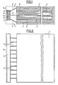
- the panel shown in the figures intended in particular for construction and which can form at least in part an exterior wall of an industrial or commercial building and capable of serving as a heating, refrigeration or air conditioning element of the interior of said habitat is presents substantially in the form of a parallelepiped.
- the panel comprises an interior heat exchanger generally identified by the reference 1, an exterior heat exchanger generally identified by the reference 2 and a thermal storage enclosure 3 disposed between the interior heat exchanger 1 and the external exchanger 2 inside the panel.
- the interior heat exchanger 1 comprises an interior heat exchange surface 4 forming, in the example shown, part of the interior face of the panel so as to be in contact with the interior volume of said habitat, a plate 5 disposed at near one end of the panel and substantially vertically as well as a multiplicity of heat transfer conduits 6 disposed substantially in a vertical plane capable of effecting a thermal connection between the internal exchange surface and the plate 5 in both directions .
- the conduits 6 are sealed at their ends and inside contain a two-state heat transfer fluid.
- the heat transfer conduits 6 are arranged substantially horizontally, one end of these conduits penetrating inside the plate 5 while most of their length is in contact with the internal exchange surface. 4 so as to create a good heat exchange between this internal exchange surface 4 and the heat transfer fluid.
- the exterior heat exchanger comprises an exterior heat exchange surface 7 intended to be in contact with the exterior environment of said building and forming in part the exterior face of the panel, a plate 8 disposed substantially vertically in the vicinity of the same end of the panel. that the plate 5 of the indoor heat exchanger 1 as well as a multiplicity of heat transfer conduits 9 disposed substantially in a vertical plane and capable of thermally connecting the external heat exchange surface 7 and the plate 8 in the both directions.
- the heat transfer conduits 9 are arranged horizontally.
- the conduits 6 and 9 are connected respectively to the heat exchange surfaces 4 and 7, inside, by known means such as yokes or welds or any other suitable means.
- the thermal storage enclosure 3 is in the form of a tank at least partially filled with water 10.
- the conduits 11 allow a transfer of heat, in both directions, between the water 10. From the thermal storage enclosure 3 and the intermediate plate 12.
- the intermediate plate 12 is thermally connected on the one hand to the plate 5 of the indoor heat exchanger 1 by a multiplicity of thermoelectric modules 13 and on the other hand to the plate 8 of the outdoor heat exchanger 2 by a multiplicity thermoelectric modules 14, thermoelectric modules capable of generating a temperature difference between their faces when they are crossed by a current.
- the thermal storage enclosure 3 is separated from the interior and exterior heat exchangers 1 and 2 by an insulating material 15.
- the panel comprises a support structure shown very schematically at 16, the elements forming the exchangers being mounted on this structure 16 by known means and adequately.
- the structure 16 may also include means, not shown, allowing the panel to be associated with the other elements forming the exterior wall of the habitat.
- the panel can be used either as a heating element or as a cooling element.
- a heating panel it is very advantageous for the external heat exchanger 2 to be in the form of a solar collector, the heat exchange surface 7 having in this case the characteristics of shape and structure of a conventional solar collector.
- the solar radiation captured by the external heat exchanger 2 can be transferred by means of the heat transfer conduits 9 to the plate 8 and, via the thermoelectric modules 14 to the intermediate plate 12. From there, the heat can be transferred to the interior environment of said habitat via thermoelectric modules 13, conduits 6 and the exchange surface 4, and to water 10 of the thermal storage enclosure 3 via transfer conduits heat 11, the heat can be transmitted only to the thermal storage enclosure 3 if the desired thermal level of the interior environment of the habitat is reached. During the periods without sunlight, the interior environment of the habitat is heated thanks to the thermal energy accumulated in the thermal storage enclosure 3, the thermoelectric modules 13 allowing the heat to pass if the thermal level in the thermal storage enclosure is sufficient or acting as a heat pump if the thermal level in the thermal storage enclosure is insufficient.
- thermoelectric modules 13 and 14 The regulation of heat transfers can be obtained by means of a regulating device, preferably electronic, not shown, capable of acting on the currents passing through the thermoelectric modules 13 and 14.
- a regulating device preferably electronic, not shown, capable of acting on the currents passing through the thermoelectric modules 13 and 14.
- the current passing through the thermoelectric modules 13 will be such that it will create a temperature difference between the opposite faces of the thermoelectric modules 13 equal to the temperature difference between the plate 5 and the intermediate plate 12 so well that there will be no heat transfer between these plates.
- the thermoelectric modules 14 will be traversed by a current such that the temperature difference between their opposite faces is permanently equal to the temperature difference between the plate 8 and the plate 12 so that n there will be no heat transfer between these plates.
- the modules 14 create a thermal barrier when the temperature difference between the enclosure and the external environment becomes too large, to the disadvantage of the external environment, in order to limit consumption. of electrical energy due to the operation of the thermoelectric modules 14 as a heat pump.
- the panel is used as a refrigeration element for the interior environment of the habitat.
- thermoelectric modules are therefore traversed by a current so as to transfer heat from the interior environment of the habitat to the exterior environment.
- thermoelectric modules operate at night, so that they cool the volume to be conditioned and the thermal storage at the same time, under small temperature differences. .
- the heat taken from the indoor environment instead of giving it directly to the outdoor environment, is preferably accumulated in the thermal storage enclosure 3, heat which will be transferred to the outside environment losing the following night.
- thermoelectric modules 13 and 14 In the same way as in the case of the heating panel, provision may be made for a regulating apparatus, preferably electronic, which will be capable of modulating the electric currents passing through the thermoelectric modules 13 and 14 so as to maintain the desired level of cold while minimizing the consumption of electrical energy thanks to storage, the modules can also act as a thermal barrier between the plates thanks to a suitable electric current.
- the present invention is not limited to the example described above and to the operating modes mentioned. Indeed, the solution proposed to solve the problems of heating, cooling or air conditioning has the advantage of being very easily adjustable in power, shape and size, so as to adapt to the climatic conditions of the site. where the installation is located, these climatic conditions can be extremely variable. In many cases, the proposed solution will remove any other heating or cooling element.
- the production of the storage enclosure cannot be limited to one or more tanks containing water.
Landscapes
- Engineering & Computer Science (AREA)
- Physics & Mathematics (AREA)
- Mechanical Engineering (AREA)
- General Engineering & Computer Science (AREA)
- Thermal Sciences (AREA)
- Combustion & Propulsion (AREA)
- Sustainable Development (AREA)
- Chemical & Material Sciences (AREA)
- Life Sciences & Earth Sciences (AREA)
- Architecture (AREA)
- Acoustics & Sound (AREA)
- Electromagnetism (AREA)
- Civil Engineering (AREA)
- Structural Engineering (AREA)
- Devices For Blowing Cold Air, Devices For Blowing Warm Air, And Means For Preventing Water Condensation In Air Conditioning Units (AREA)
- Building Environments (AREA)
- Photovoltaic Devices (AREA)
- Patch Boards (AREA)
Applications Claiming Priority (2)
| Application Number | Priority Date | Filing Date | Title |
|---|---|---|---|
| FR7925943A FR2468086A1 (fr) | 1979-10-18 | 1979-10-18 | Dispositif, panneau et procede destines au chauffage, a la refrigeration, a la climatisation ou au controle de l'humidite d'un habitat industriel ou commercial |
| FR7925943 | 1979-10-18 |
Publications (2)
| Publication Number | Publication Date |
|---|---|
| EP0027626A2 true EP0027626A2 (de) | 1981-04-29 |
| EP0027626A3 EP0027626A3 (de) | 1981-12-09 |
Family
ID=9230818
Family Applications (1)
| Application Number | Title | Priority Date | Filing Date |
|---|---|---|---|
| EP80106234A Withdrawn EP0027626A3 (de) | 1979-10-18 | 1980-10-14 | Vorrichtung, Paneel und Verfahren zur Heizung, Kühlung, Klimatisierung oder Feuchtigkeitsregelung eines industriellen oder kommerziellen Gebäudes |
Country Status (5)
| Country | Link |
|---|---|
| EP (1) | EP0027626A3 (de) |
| JP (1) | JPS5664291A (de) |
| BR (1) | BR8006691A (de) |
| FR (1) | FR2468086A1 (de) |
| OA (1) | OA06642A (de) |
Cited By (5)
| Publication number | Priority date | Publication date | Assignee | Title |
|---|---|---|---|---|
| FR2514876A1 (fr) * | 1981-10-21 | 1983-04-22 | Gimenez Christian | Isolation thermique dynamique thermodynamique a fluides paralleles |
| FR2624956A1 (fr) * | 1987-12-18 | 1989-06-23 | Sodern | Dispositif de sur-refroidissement temporaire d'un detecteur refroidi |
| WO1989006335A1 (fr) * | 1988-01-05 | 1989-07-13 | Chemonorm Ag | Groupe de refroidissement pour refrigerateur |
| NL2003188C2 (nl) * | 2009-07-10 | 2011-01-11 | Nilesk Group Ltd | Constructie-element. |
| WO2022079556A1 (en) * | 2020-10-16 | 2022-04-21 | Wyllie Nicholas | Improvements relating to cladding |
Families Citing this family (5)
| Publication number | Priority date | Publication date | Assignee | Title |
|---|---|---|---|---|
| RU2034207C1 (ru) * | 1992-11-05 | 1995-04-30 | Товарищество с ограниченной ответственностью компании "Либрация" | Способ охлаждения объекта каскадной термоэлектрической батареей |
| RU2155917C2 (ru) * | 1998-10-23 | 2000-09-10 | Оренбургский филиал МНТК "Микрохирургия глаза" | Термоэлектрическое устройство |
| CL2017003498A1 (es) * | 2017-12-29 | 2018-05-04 | Ahr Energy Spa | Método para producir transferencia de calor entre dos o mas medios y un sistema para ejecutar dicho método. |
| CN111174329B (zh) * | 2018-10-24 | 2021-11-23 | 青岛海尔空调器有限总公司 | 一种可移动的空调及其温度调节控制方法 |
| CN112611010B (zh) * | 2020-11-30 | 2022-06-28 | 华北电力大学 | 一种多热源热电联产机组发电负荷灵活调节系统的调节方法 |
Family Cites Families (19)
| Publication number | Priority date | Publication date | Assignee | Title |
|---|---|---|---|---|
| FR813991A (fr) * | 1936-02-17 | 1937-06-12 | Merlin Gerin | Dispositifs de chauffage et de réfrigération simultanés |
| FR1309750A (fr) * | 1958-12-04 | 1962-11-16 | Siemens Elektrogeraete Gmbh | Appareil frigorifique équipé de dispositifs de refroidissement électrothermiques |
| GB934114A (en) * | 1960-04-17 | 1963-08-14 | Siemens Ag | A combined refrigeration and heated-water supply apparatus |
| US3100969A (en) * | 1960-08-03 | 1963-08-20 | Thore M Elfving | Thermoelectric refrigeration |
| US3209547A (en) * | 1961-08-21 | 1965-10-05 | Thore M Elfving | Thermoelectric refrigerator and method and heat dissipating surface |
| DE1454636A1 (de) * | 1962-04-19 | 1969-01-30 | Siemens Elektrogeraete Gmbh | Mit Peltierelementen betriebene Klimaanlage |
| US3205667A (en) * | 1964-09-08 | 1965-09-14 | Edsel W Frantti | Submarine air conditioning module |
| US3500650A (en) * | 1968-05-13 | 1970-03-17 | Westinghouse Electric Corp | Multistage direct transfer thermoelectric apparatus |
| DE1801088A1 (de) * | 1968-10-01 | 1970-05-27 | Siemens Ag | Kuehleinrichtung fuer Gebaeude-Innenraeume |
| US3780262A (en) * | 1972-07-28 | 1973-12-18 | R Rudd | Thermal bank |
| DE2336667A1 (de) * | 1973-07-19 | 1975-01-30 | Franz Dipl Ing Bogdanski | Verfahren zur waermerueckgewinnung bei der beheizung von gebaeuden mit waermepumpen |
| DE2347457A1 (de) * | 1973-09-20 | 1975-04-10 | Eduard W Prof Dr Phil Justi | Stabfoermige anordnung von thermoelementpaaren |
| US4125122A (en) * | 1975-08-11 | 1978-11-14 | Stachurski John Z O | Direct energy conversion device |
| CH613764A5 (en) * | 1976-10-29 | 1979-10-15 | Max Buergin | Method of air-conditioning buildings, in particular in regions with extreme climates, and building for carrying out the same |
| DE2654732A1 (de) * | 1976-12-02 | 1978-06-08 | Adolf H Michel | Heizsystem mit langzeitwaermespeicher |
| FR2407447A1 (fr) * | 1977-10-26 | 1979-05-25 | Lutard Francois | Association pompe a chaleur-caloduc |
| FR2415273A1 (fr) * | 1978-01-20 | 1979-08-17 | Lutard Francois | Utilisation d'une pompe a chaleur en separateur d'energie calorifique |
| DE2910156A1 (de) * | 1979-03-15 | 1980-09-25 | Holger Simon | Waermepumpenheizung und -kuehlung fuer direktheiz- und speicherbetrieb mittels peltierelementen |
| FR2459556A1 (fr) * | 1979-06-19 | 1981-01-09 | Moracchioli R | Procede et dispositif pour le transfert de chaleur entre au moins deux sources de chaleur de maniere a les maintenir a des niveaux thermiques differents |
-
1979
- 1979-10-18 FR FR7925943A patent/FR2468086A1/fr not_active Withdrawn
-
1980
- 1980-10-14 EP EP80106234A patent/EP0027626A3/de not_active Withdrawn
- 1980-10-15 JP JP14306380A patent/JPS5664291A/ja active Pending
- 1980-10-17 BR BR8006691A patent/BR8006691A/pt unknown
- 1980-10-18 OA OA57239A patent/OA06642A/xx unknown
Cited By (6)
| Publication number | Priority date | Publication date | Assignee | Title |
|---|---|---|---|---|
| FR2514876A1 (fr) * | 1981-10-21 | 1983-04-22 | Gimenez Christian | Isolation thermique dynamique thermodynamique a fluides paralleles |
| FR2624956A1 (fr) * | 1987-12-18 | 1989-06-23 | Sodern | Dispositif de sur-refroidissement temporaire d'un detecteur refroidi |
| EP0322028A1 (de) * | 1987-12-18 | 1989-06-28 | Societe Anonyme D'etudes Et Realisations Nucleaires S.O.D.E.R.N. | Vorrichtung zur vorübergehenden Unterkühlung eines gekühlten Detektors |
| WO1989006335A1 (fr) * | 1988-01-05 | 1989-07-13 | Chemonorm Ag | Groupe de refroidissement pour refrigerateur |
| NL2003188C2 (nl) * | 2009-07-10 | 2011-01-11 | Nilesk Group Ltd | Constructie-element. |
| WO2022079556A1 (en) * | 2020-10-16 | 2022-04-21 | Wyllie Nicholas | Improvements relating to cladding |
Also Published As
| Publication number | Publication date |
|---|---|
| BR8006691A (pt) | 1981-04-22 |
| JPS5664291A (en) | 1981-06-01 |
| OA06642A (fr) | 1981-08-31 |
| FR2468086A1 (fr) | 1981-04-30 |
| EP0027626A3 (de) | 1981-12-09 |
Similar Documents
| Publication | Publication Date | Title |
|---|---|---|
| EP0046716B1 (de) | Kühlvorrichtung mit einer strahlenden Platte und einer Verdampferplatte | |
| US4031881A (en) | Solar heater | |
| Buchberg et al. | Design considerations for solar collectors with cylindrical glass honeycombs | |
| EP0027626A2 (de) | Vorrichtung, Paneel und Verfahren zur Heizung, Kühlung, Klimatisierung oder Feuchtigkeitsregelung eines industriellen oder kommerziellen Gebäudes | |
| FR2913101A1 (fr) | Dispositif de chauffage de fluide(s) par energie solaire thermique | |
| US4566434A (en) | Solar energy collector | |
| FR2548455A1 (fr) | Collecteur solaire a pile photovoltaique | |
| EP2354713A1 (de) | Solarwärmesystem zum Beheizen eines Wohnraums | |
| US6082354A (en) | Solar collector | |
| FR2468077A1 (fr) | Capteur solaire utilisable comme chauffe-eau | |
| FR2548832A1 (fr) | Module solaire photo-electrique | |
| FR2999830B1 (fr) | Element de traitement d'un rayonnement solaire ameliore ainsi qu'un suiveur solaire et une centrale solaire equipee d'un tel element | |
| FR2558245A1 (fr) | Installation de chauffage solaire | |
| EP2354714B1 (de) | Solarwärmesystem und Verfahren zum Beheizen eines Wohnraums | |
| FR2914048A1 (fr) | Installation de chauffage central hybride et procede de commande d'une telle installation. | |
| GB1585916A (en) | Solar energy collection and delivery | |
| EP2354712B1 (de) | Solarwärmekollektor, Solarwärmesystem, das einen solchen Solarwärmekollektor umfasst, und entsprechendes Heizverfahren eines Wohnraums | |
| FR2458768A1 (fr) | Module de conversion de l'energie solaire, et centrale solaire utilisant de tels modules | |
| FR2680564A1 (fr) | Capteur solaire orientable a air avec loupes rectilignes et accumulateur a eau chaude. | |
| EP0114005A1 (de) | Einrichtung zur Erzeugung und Speicherung von Wärme | |
| FR2481422A1 (fr) | Procede et installation de production et de distribution de chaleur a l'interieur des locaux d'un immeuble | |
| FR2945857A1 (fr) | Dispositif permettant de concentrer les rayons solaires pour chauffer un fluide | |
| FR2518716A1 (fr) | Echangeur-stockeur de chaleur et capteur solaire comportant un tel echangeur | |
| CA1080069A (en) | Solar heater | |
| US4088119A (en) | Means and methods of preventing the loss of solar heat |
Legal Events
| Date | Code | Title | Description |
|---|---|---|---|
| PUAI | Public reference made under article 153(3) epc to a published international application that has entered the european phase |
Free format text: ORIGINAL CODE: 0009012 |
|
| AK | Designated contracting states |
Designated state(s): BE DE GB IT NL SE |
|
| PUAL | Search report despatched |
Free format text: ORIGINAL CODE: 0009013 |
|
| AK | Designated contracting states |
Designated state(s): BE DE GB IT NL SE |
|
| 17P | Request for examination filed |
Effective date: 19820611 |
|
| STAA | Information on the status of an ep patent application or granted ep patent |
Free format text: STATUS: THE APPLICATION IS DEEMED TO BE WITHDRAWN |
|
| 18D | Application deemed to be withdrawn |
Effective date: 19840105 |