EP0027634A2 - Appareil enregistreur - Google Patents
Appareil enregistreur Download PDFInfo
- Publication number
- EP0027634A2 EP0027634A2 EP80106282A EP80106282A EP0027634A2 EP 0027634 A2 EP0027634 A2 EP 0027634A2 EP 80106282 A EP80106282 A EP 80106282A EP 80106282 A EP80106282 A EP 80106282A EP 0027634 A2 EP0027634 A2 EP 0027634A2
- Authority
- EP
- European Patent Office
- Prior art keywords
- width
- recording
- signals
- voltage
- signal
- Prior art date
- Legal status (The legal status is an assumption and is not a legal conclusion. Google has not performed a legal analysis and makes no representation as to the accuracy of the status listed.)
- Withdrawn
Links
Images
Classifications
-
- G—PHYSICS
- G01—MEASURING; TESTING
- G01D—MEASURING NOT SPECIALLY ADAPTED FOR A SPECIFIC VARIABLE; ARRANGEMENTS FOR MEASURING TWO OR MORE VARIABLES NOT COVERED IN A SINGLE OTHER SUBCLASS; TARIFF METERING APPARATUS; MEASURING OR TESTING NOT OTHERWISE PROVIDED FOR
- G01D9/00—Recording measured values
- G01D9/28—Producing one or more recordings, each recording being of the values of two or more different variables
- G01D9/32—Producing one or more recordings, each recording being of the values of two or more different variables there being a common recording element for two or more variables
- G01D9/34—Producing one or more recordings, each recording being of the values of two or more different variables there being a common recording element for two or more variables the variables being recorded in a predetermined sequence
Definitions
- the invention relates to a writing instrument with a writing element and a recording medium, which can be displaced relative to one another for recording measurement signals on the recording medium and wherein the writing element is designed to record a plurality of signals on the recording medium.
- the object of the present invention is to construct a writing instrument of the type mentioned at the outset which optimally fulfills the above conditions as a whole.
- a single write head as a writing element on the record carrier a variable number, for. B. between one and sixteen, of recording tracks for measurement signals is assigned, in which the write head can be retracted by a motor drive in chronological succession for recording the signals in time-division multiplex operation, the width of a respectively preselected track being predetermined by a width selector corresponding to one
- the latitude program to be set in advance specifies the latitudes and is followed by a latitude / voltage converter, which generates a more or less rapidly increasing ramp voltage depending on the latitude to be written out, which together with the signal values obtained in multiplex operation is used by a comparator for comparison and for outputting a Write signals are fed to the write head for recording a signal point when the voltage values are equal.
- the invention enables optimal variability in signal recording with optimally low mechanical and electronic complexity. With just a single write head, it is possible to display a total of up to, for example, sixteen signals or any subcombinations of these signals according to the program on a single recording pad in recording tracks of the same or any width.
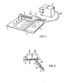
- Fig. 1 shows the writing instrument 1, which comprises a slide rail 2, on the underside of which a write head 3 is mounted in the Y direction along the rail and together with the rail in the X direction.
- the write head 3 is heatable in the present case.
- the record carrier is designated 4 and lies on a writing pad 5 of the device.
- Thermosensitive paper is used as the material, which leaves 3 recording tracks for the respective signal when the heated print head is pressed.
- training as a thermosensitive writer is only an example.
- Other pens such as pen pens, ink jet pens, droplet pens, etc., can of course also be used within the scope of the invention.
- 6 with a motor drive for the displacement movement in the X or Y direction is designated.
- a control device for controlling the writing movement via the motor drive 6 and for generating writing signals for the write head 3 is indicated at 7. Desired control programs can be set using switches 8 and 9. Energy supply for motor drive and heating as well as signaling are carried out via a cable 10.
- the writing instrument of FIG. 1 operates in time-division multiplex mode; corresponding to the write head writes 3 measurement signals 11 by stepwise transverse clocking on the Y-axis with each subsequent further circuit by one clock step in X-direction point for point in time multi-p lex operation.
- Fig. 2 shows that the motor drive 6 comprises a total of two motors 12 and 13, which are designed here as stepper motors.
- the motor 12 operates step movement in the X direction via the belt drive 14 and the motor 13 effects step movement in the Y direction via the belt drive 15.
- the write head 3 is located on the underside of the slider 16 which can be displaced in the X direction by the belt drive 15
- the structure of FIG. 2 can be covered by the slide rail 2 of FIG. 1 as far as the belt drive 15 is concerned. Of course, an additional covering slide rail can be dispensed with if required. Other modification options are also possible.
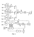
- FIG. 3 The special circuit arrangement for operating the writing instrument of FIGS. 1 and 2 is shown in FIG. 3.
- a total of 48 measurement signals can thus be used in time-division multiplexing in parallel with one another or, if necessary, in itself when fully used record overlapping or overlapping webs. By omitting individual signals at certain signal inputs, the number of signals to be displayed can be reduced in any way.
- the signal information obtained at the outputs of the time-division multiplexing circuit arrangements 17 to 19 in time-division multiplexing is given to one input by the comparators 21, 22 and 23.
- a ramp voltage U RY which is generated by a further time-division multiplex arrangement 24 with a digital-to-analog converter 25 connected downstream.
- the time-division multiplex arrangement 24 in turn has sixteen voltage inputs at which direct voltages U1 to U16 are present.
- the direct voltages U1 to U16 can be preselectable according to the program; for example, they can be stepped in the same volt steps, for example 1 volt step. There is also the possibility of other combinations of steps.
- a more or less rapidly increasing ramp voltage U R results at the output of the digital / analog converter 25.
- This ramp voltage U R is compared in a further comparator 26 with a reference voltage U ref . If the voltages are equal, the comparator 26 generates an output signal which sets a monostable multivibrator 27.
- a channel counter 28 is driven, which is coupled on the output side to the time-division multiplex arrangements 17, 18, 19 and 24; on the other hand, the monostable multivibrator 27 resets a binary counter 29 which counts pulses from a quartz oscillator 30.
- the pulses of the quartz oscillator 30 are simultaneously step pulses for the drive circuit 31 of the X stepper motor 12 and the Y step motors 13.
- the binary counter 29 is coupled to the digital-to-analog converter 25 via the signal lines 32.
- the overall arrangement 24 to 31 described is used to determine the number of recording tracks for individual measurement signals on the recording medium 4 or the preselection of the width of individual recording tracks for a predetermined total number.
- the preselection of the voltage values U1 to U16 on the time-division multiplex arrangement 24 serving as a width selector there is, as already indicated, a more or less rapid increase in the ramp voltage UR at the output of the digital-to-analog converter 25.
- the comparative voltage U ref also reached more or less quickly at the comparator 26.
- the monostable multivibrator 27 is set faster or possibly less quickly, which in turn causes the binary counter 29 to be reset more quickly or less quickly.
- the time-division multiplex arrangement 24 serves as a width selector, on which the desired width of individual, pre-selected number of recording tracks can be predetermined by preselecting certain voltages U1 to U16, then the digital-to-analog converter 25 can be referred to as a width / voltage converter, which in Connection with its ramp output voltage U R and the circuit elements 28 to 29 described above determines the widths of individual tracks to be preselected on the recording medium 4.
- the number of measurement signals to be assigned to a single recording path can be determined by preselecting individual signal voltages 1a to 16c on the time-division multiplexing arrangements 17 to 19 in connection with the ramp voltage U R via the comparators 21 to 23.
- the width of a recording track is chosen to be relatively large, then be there is the possibility, by preselecting a larger number of signals, to represent all of these signals in this single wide strip. It is also possible to select only a single signal or just a few. With the chosen large width, the signal is then expanded in amplitude, so that a wider amplitude curve results compared to other recording tracks.
- Fig. 1 shows a recording scheme in e.g. B. four tracks I, II, III, IV, with two measurement signals being recorded in track I, only one measurement signal in tracks II and III, and finally a total of three measurement signals being recorded in track IV.
- the recording of the individual signals according to the preselected number and division into recording tracks takes place depending on the output signals of the comparators 21, 22 and 23 via differentiating capacitors 32, 33 and 34.
- the differentiating pulses of these capacitors, which are generated in the desired sampling scheme of the measurement signals in time-division multiplexing are set via a summing circuit 35 a further monostable multivibrator 36 which provides output pulses which are passed on to the write head 3 via a power output stage 37 as the write pulses actuating the heating of the write head.
- the shift clock in the X direction defines the course of time over the time axis extending in the X direction.
- a writing instrument is thus created in which only one single recording head, the recording of a large number of measurement signals in any combination in a predeterminable number of recording tracks is possible on a single recording medium.
Landscapes
- Physics & Mathematics (AREA)
- General Physics & Mathematics (AREA)
- Recording Measured Values (AREA)
- Digital Magnetic Recording (AREA)
Applications Claiming Priority (2)
| Application Number | Priority Date | Filing Date | Title |
|---|---|---|---|
| DE2942614 | 1979-10-22 | ||
| DE19792942614 DE2942614A1 (de) | 1979-10-22 | 1979-10-22 | Schreibgeraet |
Publications (2)
| Publication Number | Publication Date |
|---|---|
| EP0027634A2 true EP0027634A2 (fr) | 1981-04-29 |
| EP0027634A3 EP0027634A3 (fr) | 1983-04-06 |
Family
ID=6084065
Family Applications (1)
| Application Number | Title | Priority Date | Filing Date |
|---|---|---|---|
| EP80106282A Withdrawn EP0027634A3 (fr) | 1979-10-22 | 1980-10-15 | Appareil enregistreur |
Country Status (4)
| Country | Link |
|---|---|
| US (1) | US4331963A (fr) |
| EP (1) | EP0027634A3 (fr) |
| JP (1) | JPS56103320A (fr) |
| DE (1) | DE2942614A1 (fr) |
Families Citing this family (2)
| Publication number | Priority date | Publication date | Assignee | Title |
|---|---|---|---|---|
| US4591872A (en) * | 1982-09-27 | 1986-05-27 | Power Science, Inc. | X-Y distinguishable multi-trace coding for multiparameter recording of a single stylus recorder |
| JPS63142967A (ja) * | 1986-12-05 | 1988-06-15 | Furuno Electric Co Ltd | ファクシミリ記録器 |
Family Cites Families (6)
| Publication number | Priority date | Publication date | Assignee | Title |
|---|---|---|---|---|
| US3321767A (en) * | 1965-01-11 | 1967-05-23 | Salvatore A Fulchino | Automatic logging system |
| US3500433A (en) * | 1965-11-08 | 1970-03-10 | Litton Systems Inc | Precision depth recorder |
| US3605111A (en) * | 1970-03-19 | 1971-09-14 | Clevite Corp | Trace-interrupting multichannel recorder |
| US3754280A (en) * | 1972-03-17 | 1973-08-21 | Honeywell Inc | Apparatus for producing recorded traces of uniform density |
| US4051482A (en) * | 1976-04-26 | 1977-09-27 | American Optical Corporation | Graticule with cursors |
| US4083040A (en) * | 1976-04-30 | 1978-04-04 | Honeywell Inc. | Trace locator for a multi-trace recorder |
-
1979
- 1979-10-22 DE DE19792942614 patent/DE2942614A1/de not_active Withdrawn
-
1980
- 1980-10-15 EP EP80106282A patent/EP0027634A3/fr not_active Withdrawn
- 1980-10-21 JP JP14749780A patent/JPS56103320A/ja active Pending
- 1980-10-21 US US06/199,120 patent/US4331963A/en not_active Expired - Lifetime
Also Published As
| Publication number | Publication date |
|---|---|
| US4331963A (en) | 1982-05-25 |
| EP0027634A3 (fr) | 1983-04-06 |
| JPS56103320A (en) | 1981-08-18 |
| DE2942614A1 (de) | 1981-04-30 |
Similar Documents
| Publication | Publication Date | Title |
|---|---|---|
| DE2727583C2 (de) | Elektroencephalograph | |
| DE2425679B2 (de) | Vorrichtung zum Erzeugen und selektiven Ablenken von Flüssigkeitströpfchen | |
| DE2311601B2 (de) | Tintenstrahlschreiber | |
| DE2434963A1 (de) | Schreibeinrichtung zur aufzeichnung des verlaufs mindestens einer messgroesse | |
| EP0027634A2 (fr) | Appareil enregistreur | |
| DE2709320A1 (de) | Verfahren zur wiedergabe von buchstaben oder symbolen | |
| DE2900626C3 (de) | Verfahren zur Anzeige einer Schalterstellung in einer Signalregistriervorrichtung, sowie Signalregistriervorrichtung zur Durchführung dieses Verfahrens | |
| DE2113187C3 (de) | Hochgeschwindigkeits- Vielfachstreifenschreiber | |
| EP0452249B1 (fr) | Appareil enregistreur | |
| DE2915356A1 (de) | Textbearbeitungsgeraet | |
| DE2727831A1 (de) | Matrixverstaerkerschaltung, insbesondere fuer magnetische plattenspeicher | |
| DE1498113C3 (de) | Registriergerät | |
| DE4418787C2 (de) | Linienschreiber | |
| DE2114234A1 (de) | Graphische Datenaufzeichnungs- und -integrieranordnung | |
| DE2411509C2 (fr) | ||
| DE1448915C (de) | Gerat zur Darstellung der Haufigkeits verteilung | |
| DE1548578C (de) | Elektrisches Schreibgerat | |
| DE2718329A1 (de) | Schaltungsanordnung zur anzeige der jeweiligen lage des spurpunktes einer aufzeichnung | |
| DE3045011C2 (de) | Zahnärztlicher Behandlungsplatz | |
| DE2304740A1 (de) | Schreibvorrichtung zur graphischen wiedergabe von alphanumerischen zeichen auf einem registrierstreifen | |
| DE2515557A1 (de) | Matrixdrucker, bei dem die schriftzeichenbreite der ausgedruckten schriftzeichen veraenderbar ist | |
| DE2544760C2 (de) | Schaltungsanordnung zur Ansteuerung eines elektrosensitiven Schreibwerkes | |
| DE2835633A1 (de) | Verwendung eines alphanumerischen druckers zur analogbilddarstellung | |
| DE1538375C (de) | Steuereinrichtung | |
| DE2406354C3 (de) | Vorrichtung zum elektrischen Lesen eines Informationsträgers |
Legal Events
| Date | Code | Title | Description |
|---|---|---|---|
| PUAI | Public reference made under article 153(3) epc to a published international application that has entered the european phase |
Free format text: ORIGINAL CODE: 0009012 |
|
| AK | Designated contracting states |
Designated state(s): DE GB SE |
|
| 17P | Request for examination filed |
Effective date: 19811030 |
|
| PUAL | Search report despatched |
Free format text: ORIGINAL CODE: 0009013 |
|
| AK | Designated contracting states |
Designated state(s): DE GB SE |
|
| STAA | Information on the status of an ep patent application or granted ep patent |
Free format text: STATUS: THE APPLICATION IS DEEMED TO BE WITHDRAWN |
|
| 18D | Application deemed to be withdrawn |
Effective date: 19850301 |
|
| RIN1 | Information on inventor provided before grant (corrected) |
Inventor name: OLSSON, SVEN GUNNAR Inventor name: DAHLSTROEM, BO |