EP0027675B1 - Automatisierte Presse zum Formen von Schleifscheiben - Google Patents
Automatisierte Presse zum Formen von Schleifscheiben Download PDFInfo
- Publication number
- EP0027675B1 EP0027675B1 EP80200983A EP80200983A EP0027675B1 EP 0027675 B1 EP0027675 B1 EP 0027675B1 EP 80200983 A EP80200983 A EP 80200983A EP 80200983 A EP80200983 A EP 80200983A EP 0027675 B1 EP0027675 B1 EP 0027675B1
- Authority
- EP
- European Patent Office
- Prior art keywords
- press
- mould
- conveyor
- pincer
- platen
- Prior art date
- Legal status (The legal status is an assumption and is not a legal conclusion. Google has not performed a legal analysis and makes no representation as to the accuracy of the status listed.)
- Expired
Links
Images


Classifications
-
- B—PERFORMING OPERATIONS; TRANSPORTING
- B24—GRINDING; POLISHING
- B24D—TOOLS FOR GRINDING, BUFFING OR SHARPENING
- B24D18/00—Manufacture of grinding tools or other grinding devices, e.g. wheels, not otherwise provided for
- B24D18/009—Tools not otherwise provided for
-
- B—PERFORMING OPERATIONS; TRANSPORTING
- B30—PRESSES
- B30B—PRESSES IN GENERAL
- B30B15/00—Details of, or accessories for, presses; Auxiliary measures in connection with pressing
- B30B15/30—Feeding material to presses
Definitions
- an automatic press for moulding grinding wheels incorporating two or more reinforcing gauzes, a wheel hub for the wheel bore and a marking label said moulding press comprising:
- the press in question in its general layout, is of a conventional kind well known to those skilled in the art and which comprises a bottom platen 10 and a top platen 11.
- the platens 10 and 11 carry, respectively, the male and the female moulds used for shaping the grinding wheels.
- the top platen 11 is vertically movable in the direction of the arrow 12, whereas the bottom platen 10 is horizontally movable in the direction of the arrow 13.
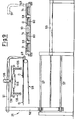
- the platen 10 is shifted from a working position of shaping of the grinding wheel, in alignment with the platen 11, to a position of mould loading and unloading, wherein the platen 10 is offset relative to the platen 11 in a position outside the press, as shown in FIGURE 1.
- FIGURE 1 of the drawings are generally indicated at 20 and 21, respectively.
- the set 20 is intended automatically to feed the moulds 14 with the gauzes 22 to reinforce the abrasive mix, a wheel hub 23 for the central wheel bore of the wheel D and a marking label 25 (FIGURE 10).
- the set 21, conversely, is intended automatically to remove, from the moulds 14, the finished grinding wheel D (FIGURE 8).
- Each pincer 35 comprises two arms 39, 40 pivotally connected at 41.
- the arm 39 is fastened to the frame 36, whereas the arm 40 can be rotated about 41 against the bias of a spring 42.
- the concurrent rotation of the arms 40 of the couple of pincers 35 is controlled by the stems 43 of two confrontingly assembled pistons 44 displaceable in the interior of a ram 45 against the bias of springs 46.
- Each pincer 35 in addition, is surrounded by a sleeve 47, the latter being axially slidable and terminated by a flange 48, the purpose of which will be explained hereinafter.
- the set 21 is structurally comprised of a suction apron 49, which is connected to a suction pump 50 through a stiff tube 51 and a hose 52.
- the suction apron 49 is as wide as the platen 10 and has a comparatively narrow suction slot.
- the stiff tube 51 is borne by a framing 53 and is movable in the direction of the arrow 54 by the agency of an actuating ram 55. More detailedly, the tube 51 is borne by an upright 56 slidable on ways 57 which overhangingly extend from the framing 53.
- the tube 51 in its shank close to the apron 49 carries, moreover, a couple of pincers 135 which, both as to their structure and their operability, are substantially a counterpart of the pincers 35 of the set 20 described hereinabove.
- the only difference is that the pincers 135 do not have the sleeve 47 or the relevant flange 48, either.
- the component parts of the pincers 135, depicted in FIGURES 6, 7, 8 and 9, will not be described in detail and carry the same numerical references as the pincers 35 but increased by 100.
- the operator deposits on a couple of dishes 29 the hub 23, the label 25, and the gauze 22 (FIGURE 2) and, on the next oncoming dish coupled 29 a gauze 22 only, and so forth in the same alternate sequence.
- the conveyor 26 is moved stepwise so as to bring each couple of dishes 29 with their charge into alignment with the couple of pincers 35 of the carriage 32 (FIGURE 2).
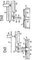
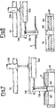
- the pincers 35 are lowered form the position of FIGURE 2 to that of FIGURE 3 so as to become inserted into the assembly 23, 25 and 22, by axial depression of the plug 30 and relative motion between the pincers 35 and the respective flanges 48.
- the pincers 35 are then closed from the position of FIGURE 2 to the position of FIGURE 3 and lifted to the position of FIGURE 4.
- the carriage 32 is then moved from the position shown in FIGURE 1 in dotted lines (also shown in the detail of FIGURE 4).
- the moulds 14 are filled with the abrasive mix 15 by shifting the hopper 16 in the direction of the arrow 17.
- a second gauze 32 is placed, which has been withdrawn from the dishes 29 by the pincers 35 in the same way as described above with reference to the assembly 23, 25, 22.
- the platen 10 is then moved under the platen 11, the mix is compressed and the platen 10 is brought back to the position of FIGURE 1, outside the press, for withdrawing the finished grinding wheels.
- the set 21 has been shifted to the position shown in dash and dot lines in FIGURE 9 and the pincers 135, which are open, are lowered from the position of FIGURE 6 to the position of FIGURE 7 wherein they are closed on the central bore of the moulded wheel after that the bottom wall 60 has been lifted (by extractor of conventional make, not shown) to prevent any interference by the plug 59.
- the pincers 135 are then lifted to the position of FIGURE 8 and carry with themselves the finished grinding wheel D.
- the set 21 is eventually brought back to the position of FIGURE 9 on the conveyor 58 onto which the wheels are deposited as the pincers 135 are opened.
- the suction apron 49 provides to sweep out of the platen 11 the residues of abrasive flour, thus preventing it from becoming airborne and from causing any damage to the attendants.
Landscapes
- Engineering & Computer Science (AREA)
- Mechanical Engineering (AREA)
- Manufacturing & Machinery (AREA)
- Finish Polishing, Edge Sharpening, And Grinding By Specific Grinding Devices (AREA)
- Polishing Bodies And Polishing Tools (AREA)
- Pens And Brushes (AREA)
Claims (6)
Priority Applications (1)
| Application Number | Priority Date | Filing Date | Title |
|---|---|---|---|
| AT80200983T ATE4179T1 (de) | 1979-10-22 | 1980-10-17 | Automatisierte presse zum formen von schleifscheiben. |
Applications Claiming Priority (2)
| Application Number | Priority Date | Filing Date | Title |
|---|---|---|---|
| IT26688/79A IT1125546B (it) | 1979-10-22 | 1979-10-22 | Pressa automatica per lo stampaggio di dischi abrasivi |
| IT2668879 | 1979-10-22 |
Publications (2)
| Publication Number | Publication Date |
|---|---|
| EP0027675A1 EP0027675A1 (de) | 1981-04-29 |
| EP0027675B1 true EP0027675B1 (de) | 1983-07-20 |
Family
ID=11220041
Family Applications (1)
| Application Number | Title | Priority Date | Filing Date |
|---|---|---|---|
| EP80200983A Expired EP0027675B1 (de) | 1979-10-22 | 1980-10-17 | Automatisierte Presse zum Formen von Schleifscheiben |
Country Status (6)
| Country | Link |
|---|---|
| EP (1) | EP0027675B1 (de) |
| AT (1) | ATE4179T1 (de) |
| CA (1) | CA1164168A (de) |
| DE (1) | DE3064307D1 (de) |
| ES (1) | ES496132A0 (de) |
| IT (1) | IT1125546B (de) |
Families Citing this family (5)
| Publication number | Priority date | Publication date | Assignee | Title |
|---|---|---|---|---|
| IT1287603B1 (it) * | 1996-12-19 | 1998-08-06 | S I T Societa Italiana Tecnosp | Procedimento per la realizzazione di spazzole e spazzola cosi' realizzata |
| US6878051B2 (en) | 2003-02-05 | 2005-04-12 | Saint-Gobain Abrasives Technology Company | Saw blade with shaped gullets |
| CN113021202B (zh) * | 2019-12-24 | 2025-05-09 | 郑州大华机电技术有限公司 | 一种半自动摊料机 |
| CN111348283B (zh) * | 2020-04-20 | 2025-02-11 | 珠海泰达砂轮有限公司 | 一种用于全自动贴标机的90°机械手机构 |
| CN112872607B (zh) * | 2021-02-22 | 2023-06-09 | 济南锐骏自动化设备有限公司 | 一种全自动铝轮毂打标装置 |
Family Cites Families (4)
| Publication number | Priority date | Publication date | Assignee | Title |
|---|---|---|---|---|
| FR1252515A (fr) * | 1960-03-31 | 1961-01-27 | Philips Nv | Dispositif destiné à prendre et à soulever des objets minces et des feuilles, en particulier des étiquettes pour disques phonographiques |
| FR1556866A (de) * | 1967-03-24 | 1969-02-07 | ||
| JPS5231596B1 (de) * | 1970-05-29 | 1977-08-16 | ||
| US3722710A (en) * | 1970-10-23 | 1973-03-27 | Carborundum Co | Work carrier for abrasive cleaning arrangements |
-
1979
- 1979-10-22 IT IT26688/79A patent/IT1125546B/it active
-
1980
- 1980-10-17 DE DE8080200983T patent/DE3064307D1/de not_active Expired
- 1980-10-17 AT AT80200983T patent/ATE4179T1/de active
- 1980-10-17 EP EP80200983A patent/EP0027675B1/de not_active Expired
- 1980-10-21 ES ES496132A patent/ES496132A0/es active Granted
- 1980-10-22 CA CA000363003A patent/CA1164168A/en not_active Expired
Also Published As
| Publication number | Publication date |
|---|---|
| CA1164168A (en) | 1984-03-27 |
| ATE4179T1 (de) | 1983-08-15 |
| ES8200266A1 (es) | 1981-11-16 |
| DE3064307D1 (en) | 1983-08-25 |
| EP0027675A1 (de) | 1981-04-29 |
| IT7926688A0 (it) | 1979-10-22 |
| ES496132A0 (es) | 1981-11-16 |
| IT1125546B (it) | 1986-05-14 |
Similar Documents
| Publication | Publication Date | Title |
|---|---|---|
| CN209811639U (zh) | 一种转盘式自动装配机 | |
| CN112060306A (zh) | 一种陶瓷碗坯自动成型机 | |
| DE69411088T2 (de) | Verfahren zur Fertigbearbeitung eines Grünkörpers | |
| EP0027675A1 (de) | Automatisierte Presse zum Formen von Schleifscheiben | |
| US4047864A (en) | Apparatus for producing spherical articles | |
| CN109202444A (zh) | 一种滚筒芯轴的装配设备 | |
| US4967810A (en) | Multi-color loading machines for cosmetic paste materials | |
| CN112172230A (zh) | 一种化妆用品眼影按压装置 | |
| CN209830267U (zh) | 一种液压机的均匀下料机构 | |
| CN222038939U (zh) | 一种砖坯成型顶出装置 | |
| CN108189209B (zh) | 高精度耐火材料自动称重布料集成系统及布料方法 | |
| CN220946847U (zh) | 一种石墨匣钵压制成型装置 | |
| US4230653A (en) | Method for producing spherical articles | |
| CN117637336B (zh) | 一种软磁铁氧体磁芯元件压制成型设备及其方法 | |
| CN210299321U (zh) | 一种茯砖茶筑茶装置 | |
| CN119427621A (zh) | 一种刹车片热压成型机及其成型工艺 | |
| CN217891674U (zh) | 一种智能手表表盖高效脱模加工模具 | |
| CN212822672U (zh) | 一种冶金用粉末金属上料设备 | |
| CN213593713U (zh) | 一种用于易拉罐回收的压缩烘干设备 | |
| CN216705611U (zh) | 一种自动化压铸模具清理装置 | |
| CN212073054U (zh) | 全自动复合布料一次成型滑板液压机 | |
| US4718474A (en) | Mold transfer mechanism for a molding machine | |
| CN110693171B (zh) | 一种应用于化妆品的脱模机 | |
| CN109434392B (zh) | 轴承生产工艺及轴承生产系统 | |
| CN224253200U (zh) | 一种经uv喷涂机喷涂后的成品号牌的自动化收料装置 |
Legal Events
| Date | Code | Title | Description |
|---|---|---|---|
| PUAI | Public reference made under article 153(3) epc to a published international application that has entered the european phase |
Free format text: ORIGINAL CODE: 0009012 |
|
| AK | Designated contracting states |
Designated state(s): AT BE CH DE FR GB LU NL SE |
|
| 17P | Request for examination filed |
Effective date: 19810925 |
|
| GRAA | (expected) grant |
Free format text: ORIGINAL CODE: 0009210 |
|
| AK | Designated contracting states |
Designated state(s): AT BE CH DE FR GB LI LU NL SE |
|
| PG25 | Lapsed in a contracting state [announced via postgrant information from national office to epo] |
Ref country code: SE Effective date: 19830720 Ref country code: NL Effective date: 19830720 Ref country code: FR Free format text: THE PATENT HAS BEEN ANNULLED BY A DECISION OF A NATIONAL AUTHORITY Effective date: 19830720 Ref country code: BE Effective date: 19830720 |
|
| REF | Corresponds to: |
Ref document number: 4179 Country of ref document: AT Date of ref document: 19830815 Kind code of ref document: T |
|
| REF | Corresponds to: |
Ref document number: 3064307 Country of ref document: DE Date of ref document: 19830825 |
|
| RAP2 | Party data changed (patent owner data changed or rights of a patent transferred) |
Owner name: DAVIDE MATERNINI S.R.L. |
|
| PG25 | Lapsed in a contracting state [announced via postgrant information from national office to epo] |
Ref country code: LU Free format text: LAPSE BECAUSE OF NON-PAYMENT OF DUE FEES Effective date: 19831031 |
|
| NLV1 | Nl: lapsed or annulled due to failure to fulfill the requirements of art. 29p and 29m of the patents act | ||
| EN | Fr: translation not filed | ||
| PLBE | No opposition filed within time limit |
Free format text: ORIGINAL CODE: 0009261 |
|
| STAA | Information on the status of an ep patent application or granted ep patent |
Free format text: STATUS: NO OPPOSITION FILED WITHIN TIME LIMIT |
|
| 26N | No opposition filed | ||
| PGFP | Annual fee paid to national office [announced via postgrant information from national office to epo] |
Ref country code: CH Payment date: 19841030 Year of fee payment: 5 |
|
| PGFP | Annual fee paid to national office [announced via postgrant information from national office to epo] |
Ref country code: DE Payment date: 19841227 Year of fee payment: 5 |
|
| GBPC | Gb: european patent ceased through non-payment of renewal fee | ||
| PGFP | Annual fee paid to national office [announced via postgrant information from national office to epo] |
Ref country code: AT Payment date: 19851016 Year of fee payment: 6 |
|
| PG25 | Lapsed in a contracting state [announced via postgrant information from national office to epo] |
Ref country code: AT Effective date: 19861017 |
|
| PG25 | Lapsed in a contracting state [announced via postgrant information from national office to epo] |
Ref country code: LI Effective date: 19861031 Ref country code: CH Effective date: 19861031 |
|
| REG | Reference to a national code |
Ref country code: CH Ref legal event code: PL |
|
| PG25 | Lapsed in a contracting state [announced via postgrant information from national office to epo] |
Ref country code: DE Effective date: 19870701 |
|
| PG25 | Lapsed in a contracting state [announced via postgrant information from national office to epo] |
Ref country code: GB Effective date: 19881118 |