EP0027771A1 - Rohrverbindung für die Erdölindustrie - Google Patents
Rohrverbindung für die Erdölindustrie Download PDFInfo
- Publication number
- EP0027771A1 EP0027771A1 EP80401547A EP80401547A EP0027771A1 EP 0027771 A1 EP0027771 A1 EP 0027771A1 EP 80401547 A EP80401547 A EP 80401547A EP 80401547 A EP80401547 A EP 80401547A EP 0027771 A1 EP0027771 A1 EP 0027771A1
- Authority
- EP
- European Patent Office
- Prior art keywords
- male elements
- sleeve
- male
- joint
- joint according
- Prior art date
- Legal status (The legal status is an assumption and is not a legal conclusion. Google has not performed a legal analysis and makes no representation as to the accuracy of the status listed.)
- Granted
Links
- 238000007789 sealing Methods 0.000 claims abstract description 41
- 230000002093 peripheral effect Effects 0.000 claims description 7
- 239000002184 metal Substances 0.000 claims description 5
- 229910000831 Steel Inorganic materials 0.000 description 6
- 239000004810 polytetrafluoroethylene Substances 0.000 description 6
- 229920001343 polytetrafluoroethylene Polymers 0.000 description 6
- 239000010959 steel Substances 0.000 description 6
- 238000004519 manufacturing process Methods 0.000 description 4
- 239000003208 petroleum Substances 0.000 description 4
- 229910001220 stainless steel Inorganic materials 0.000 description 4
- 239000010935 stainless steel Substances 0.000 description 4
- 230000000694 effects Effects 0.000 description 3
- 101100006960 Caenorhabditis elegans let-2 gene Proteins 0.000 description 1
- 238000004026 adhesive bonding Methods 0.000 description 1
- 239000011248 coating agent Substances 0.000 description 1
- 238000000576 coating method Methods 0.000 description 1
- 230000008602 contraction Effects 0.000 description 1
- 230000006866 deterioration Effects 0.000 description 1
- 239000012530 fluid Substances 0.000 description 1
- 238000009776 industrial production Methods 0.000 description 1
- 230000009916 joint effect Effects 0.000 description 1
- 239000007788 liquid Substances 0.000 description 1
- 238000003754 machining Methods 0.000 description 1
- 239000004033 plastic Substances 0.000 description 1
- 230000002522 swelling effect Effects 0.000 description 1
Images
Classifications
-
- E—FIXED CONSTRUCTIONS
- E21—EARTH OR ROCK DRILLING; MINING
- E21B—EARTH OR ROCK DRILLING; OBTAINING OIL, GAS, WATER, SOLUBLE OR MELTABLE MATERIALS OR A SLURRY OF MINERALS FROM WELLS
- E21B17/00—Drilling rods or pipes; Flexible drill strings; Kellies; Drill collars; Sucker rods; Cables; Casings; Tubings
- E21B17/02—Couplings; joints
- E21B17/04—Couplings; joints between rod or the like and bit or between rod and rod or the like
- E21B17/042—Threaded
-
- F—MECHANICAL ENGINEERING; LIGHTING; HEATING; WEAPONS; BLASTING
- F16—ENGINEERING ELEMENTS AND UNITS; GENERAL MEASURES FOR PRODUCING AND MAINTAINING EFFECTIVE FUNCTIONING OF MACHINES OR INSTALLATIONS; THERMAL INSULATION IN GENERAL
- F16L—PIPES; JOINTS OR FITTINGS FOR PIPES; SUPPORTS FOR PIPES, CABLES OR PROTECTIVE TUBING; MEANS FOR THERMAL INSULATION IN GENERAL
- F16L15/00—Screw-threaded joints; Forms of screw-threads for such joints
- F16L15/001—Screw-threaded joints; Forms of screw-threads for such joints with conical threads
- F16L15/003—Screw-threaded joints; Forms of screw-threads for such joints with conical threads with sealing rings
Definitions
- the present invention relates to a joint for tubes, more specifically for steel tubes, which is intended in particular for the petroleum industry, in particular for casing columns and for the production of petroleum deposits.
- Joints of this type must have a certain number of qualities which are in practice difficult to reconcile.
- the diameter of the seal be greater than the diameter of the tube only by the smallest possible value.
- Such seals must also have a secure seal, even after repeated screwing and unscrewing, a given male end being able to be mounted on this occasion on different female ends and this despite the manufacturing tolerances which are inherent in any industrial production.
- seals ensure, as far as possible, a self-repair of the sealing surfaces because the latter are relatively often subjected to deterioration during handling on site.
- the joint according to the invention is of the type in which the ends of two male elements are joined together using a female sleeve, each male element being provided with a tapered thread, for example which engages in a corresponding female thread formed on the sleeve.
- the present invention relates to a joint for tubes, in particular for steel tubes, intended more particularly for the exploitation of petroleum deposits, of the type in which the ends provided with a thread, for example conical, of two male elements are joined by a sleeve having on each side a corresponding thread, characterized by the fact that the sleeve has in its central part a substantially cylindrical sealing surface whose axis corresponds to the axis of the joint, each male element having at the periphery of its end a corresponding substantially cylindrical sealing surface whose diameter is equal to or slightly greater than the diameter of the sealing surface of the sleeve, the ends of the male elements coming to bear axially against one another during the tightening of the joint and the space existing between the ends of the male elements at their first contact increasing from the periphery towards the center of the joint , so that when the joint is tightened, the ends of the male elements are pushed outwards to reinforce the seal by increasing the pressure on the sealing surfaces of the male elements and of the sleeve.
- a contact pressure is created on the external periphery of the ends of the male elements which first come into contact when the seal is tightened. Any subsequent tightening tends on the one hand to crush one against the other the peripheral frontal surfaces of the ends of the male elements and on the other hand to push these ends outwards, thereby increasing said contact pressure.
- the front surfaces of the ends of the male elements can have various shapes.
- the ends of the male elements may for example be very slightly concave conical, that is to say that the end of each male element may be delimited by a conical surface whose angle with the axis of the joint is slightly less than 90 °, the tops of the cones being directed towards the inside of the male elements.
- the end surfaces of the male elements have a biconical shape, the peripheral zone of the ends of the male elements having a conicity directed in the opposite direction to the conicity of their internal zone.
- the conicities of the peripheral zones of the ends of the two male elements intended to be mounted on the same sleeve are such that the first contact between the ends of the male elements takes place at the periphery of the latter.
- the ends of the male elements are then progressively crushed during tightening in the vicinity of the first point of contact until the conical surfaces of the same conicity which are on the internal zone of the ends of the male elements, come to bear against one the other to constitute a stop.
- the cylindrical sealing surface of the sleeve is extended in the direction of the threads by a surface whose diameter gradually widens, so as to allow easy engagement and automatic centering of the end.
- male elements whose sealing surfaces have a diameter equal to or greater than the diameter of the cylindrical sealing surface of the sleeve.
- two toric sealing rings for example made of PTFE, can be placed in circular grooves formed on the cylindrical sealing surface of the sleeve on either side of the point where the ends of the elements males come into contact.
- a PTFE ring in a groove made in the vicinity of the internal end of at least one of the male elements.
- the joint according to the invention has the advantage of being easy and economical to produce.
- the sealing surfaces are cylindrical surfaces whose machining is particularly easy and economical.
- the manufacturing controls are much easier to perform and can be carried out with calibers whose cost price is lower than those of the gauges generally used for the joint manufacturing controls for the petroleum industry.
- the part located in the vicinity of the internal surface is for example produced stainless steel, while the rest of the tube is made of ordinary steel.
- the relative dimensions of the threads and the lengths of the male elements are such that the ends of the male elements can come into contact and produce the deformations which make it possible to seal according to the invention before too much hooping has occurred at the thread level.
- the hooping of a male element in the sleeve is significantly greater than the hooping of the other male element in the sleeve so as to ensure during assembly and disassembly of the seal, that the sleeve always remains positioned on the same male element. It suffices for this that the tightening torque of the sleeve on the male element which must not be separated from the sleeve is of a value significantly greater than the value of the tightening torque of the other male element in the sleeve.
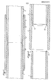
- Figures 1 and 2 show a seal according to the invention produced between two male elements 1 and 2 by means of a sleeve 3.
- the external conical threads 4 are provided at the ends of the male elements 1 and 2 to cooperate with corresponding threads 5 formed on the inner surface of the sleeve.
- These threads are preferably trapezoidal threads which vanish on the outside surface of the tubes.
- the sleeve 3 has at its central part a cylindrical female sealing surface 6 connected on either side with the internal surface of the sleeve 3 by curved surfaces 7.
- Male sealing surfaces 8 also cylindrical are provided outside the ends 9 of the male elements 1 and 2.
- the diameter of the male sealing surfaces 8 is equal to or slightly greater than the diameter of the female sealing surface 6 of the sleeve 3 so that no clearance exists between the sealing surfaces when the male elements 1 and 2 are engaged in the sleeve 3.
- the hooping which may result therefrom must not be excessive in order to avoid seizing.
- peripheral edges 10 of the male elements 1 and 2 are slightly rounded.
- these roundings have been exaggerated in the drawing. In practice, these rounding may be inexistent.nts or be constituted by a very small chamfer to "break" the sharp edge of the end of the male elements. In some cases, these rounding may take on some importance.
- the contact surfaces 11 and 12 of the male elements 1 and 2 each consist of a first external conical surface, 16 ', 17' and a second internal conical surface 16, 17 , whose taper is oriented in the opposite direction.
- the angle of inclination a of the surface 16 'of the element 1 is equal to 10 °
- the angle of inclination b of the surface 17' of the element 2 is equal at 5 °
- the angles of inclination c and d of the conical surfaces 16 and 17 of the elements 1 and 2 may for example both be equal to 10 °.
- edges 14 and 15 formed by the surfaces 16 and 16 'on the one hand and 17 and 17' on the other hand are offset by distance h in the radial direction.
- the radial offset h of the edges 14 and 15 makes it possible to limit the straightforward screwing by the contact of the surfaces 16 and 17.
- the offset ha has a value of 1 mm and a thickness at the end tubes of about 10 to 20mm.
- This assembly can advantageously be carried out in the factory while the assembly of the end of the male element 1 in the sleeve 3 (FIG. 1) is carried out on site, with a tightening torque lower than that of the male element 2 if this is not ensured on the sleeve.
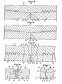
- Figures 3 and 4 show another embodiment in which the first contact of the male elements 1 and 2 is always provided at the outer periphery of these tubes.
- the space 13 widens from the outer periphery to the inner periphery of the male elements.
- the contact surfaces 19 and 20 of the ends of the male elements 1 and 2 are concave conical surfaces, that is to say conical surfaces whose apex is situated on the axis of the tubes 1 and 2 to 1 inside these male elements.
- the amount of play 21a depends on the inclination of the surfaces 19 and 20 and on the tightening of the joint. In most cases, it is preferable that this game be reduced to nothing or almost nothing, but the existence of such a game is compatible with the implementation of the invention.
- angles between the generatrices of the conical surfaces and the radial planes values of the order of 15 minutes to 30 minutes.
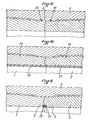
- FIG. 8 represents a variant in which two toric PTFE sealing rings 22 are housed in annular grooves provided on either side of the female sealing surface 5 of the sleeve 3.
- FIG. 9 Another variant is shown in which PTFE rings 23 are housed in recesses provided for this purpose at the internal periphery of the ends 9 of the male elements 1 and 2.
- only one PTFE ring is provided, which is preferably placed at the end of the male element 1.
- Figure 10 shows an embodiment in which the male elements let 2 are bimetallic tubes whose outer part 24 is made for example of ordinary steel while the inner part 25 is made for example of stainless steel.
- the front ends 19 and 20 of the male elements are coated with a stainless metal identical or compatible with that which constitutes the inner part 25 of the male elements.
- the present invention has been described with reference to cylindrical sealing surfaces both on the sleeve and on the ends of the male elements.
- this cylindrical shape for the sealing surfaces is the preferred shape according to the invention, one would not deviate from the spirit of the latter by making the sealing surfaces with very slightly conical shapes which do not not deviate significantly from a cylindrical shape.
- the male elements should have at their end their sealing surface having a taper in the same direction as the taper of their thread.
Landscapes
- Engineering & Computer Science (AREA)
- Geology (AREA)
- Mechanical Engineering (AREA)
- General Engineering & Computer Science (AREA)
- Life Sciences & Earth Sciences (AREA)
- Mining & Mineral Resources (AREA)
- Fluid Mechanics (AREA)
- General Life Sciences & Earth Sciences (AREA)
- Geochemistry & Mineralogy (AREA)
- Physics & Mathematics (AREA)
- Environmental & Geological Engineering (AREA)
- Non-Disconnectible Joints And Screw-Threaded Joints (AREA)
- Protection Of Pipes Against Damage, Friction, And Corrosion (AREA)
- Gasket Seals (AREA)
- Flanged Joints, Insulating Joints, And Other Joints (AREA)
- Lubricants (AREA)
- Branch Pipes, Bends, And The Like (AREA)
- Joints With Sleeves (AREA)
- Earth Drilling (AREA)
- Sealing Material Composition (AREA)
- Joints With Pressure Members (AREA)
- Rigid Pipes And Flexible Pipes (AREA)
- Polyoxymethylene Polymers And Polymers With Carbon-To-Carbon Bonds (AREA)
Priority Applications (1)
| Application Number | Priority Date | Filing Date | Title |
|---|---|---|---|
| AT80401547T ATE7328T1 (de) | 1979-10-30 | 1980-10-30 | Rohrverbindung fuer die erdoelindustrie. |
Applications Claiming Priority (2)
| Application Number | Priority Date | Filing Date | Title |
|---|---|---|---|
| FR7926890 | 1979-10-30 | ||
| FR7926890A FR2468823A1 (fr) | 1979-10-30 | 1979-10-30 | Joint pour tubes destine a l'industrie petroliere |
Publications (2)
| Publication Number | Publication Date |
|---|---|
| EP0027771A1 true EP0027771A1 (de) | 1981-04-29 |
| EP0027771B1 EP0027771B1 (de) | 1984-05-02 |
Family
ID=9231180
Family Applications (1)
| Application Number | Title | Priority Date | Filing Date |
|---|---|---|---|
| EP80401547A Expired EP0027771B1 (de) | 1979-10-30 | 1980-10-30 | Rohrverbindung für die Erdölindustrie |
Country Status (15)
| Country | Link |
|---|---|
| US (1) | US4373750A (de) |
| EP (1) | EP0027771B1 (de) |
| JP (1) | JPS56150689A (de) |
| AT (1) | ATE7328T1 (de) |
| AU (1) | AU536445B2 (de) |
| BR (1) | BR8006968A (de) |
| CA (1) | CA1156287A (de) |
| DE (1) | DE3067708D1 (de) |
| ES (2) | ES264584Y (de) |
| FR (1) | FR2468823A1 (de) |
| IE (1) | IE50172B1 (de) |
| IN (1) | IN155013B (de) |
| MX (1) | MX150843A (de) |
| NO (1) | NO803237L (de) |
| OA (1) | OA06705A (de) |
Cited By (8)
| Publication number | Priority date | Publication date | Assignee | Title |
|---|---|---|---|---|
| EP0088817A1 (de) * | 1982-03-17 | 1983-09-21 | Kawasaki Jukogyo Kabushiki Kaisha | Korrosionsbeständige Rohrkupplungskonstruktionen |
| FR2592935A1 (fr) * | 1986-01-15 | 1987-07-17 | Vallourec | Joint filete composite pour tube d'acier |
| EP0386373A3 (de) * | 1989-03-08 | 1991-11-06 | Baroid Technology, Inc. | Verbindung für Ölfeldrohre |
| EP0386372A3 (de) * | 1989-03-08 | 1991-11-27 | Baroid Technology, Inc. | Geschraubte Gestängeverbindung mit einem Dichtring |
| EP0707133A1 (de) | 1994-10-13 | 1996-04-17 | Vallourec Oil & Gas | Gewindeverbindung für Rohre |
| FR2733570A1 (fr) * | 1995-04-28 | 1996-10-31 | Vallourec Oil & Gas | Assemblage filete pour tubes |
| US5906399A (en) * | 1995-12-22 | 1999-05-25 | Vallourec Oil & Gas | Threaded joint for metal tubes with internal coating |
| CN105066490A (zh) * | 2015-08-06 | 2015-11-18 | 黑龙江省九0四环境工程勘察设计院 | 寒区地温能双壁套管式高效换热器 |
Families Citing this family (48)
| Publication number | Priority date | Publication date | Assignee | Title |
|---|---|---|---|---|
| DE3203857C2 (de) * | 1982-02-03 | 1984-08-02 | Mannesmann AG, 4000 Düsseldorf | Ölfeldrohr-Verbindung und Verfahren zum Verbinden von Ölfeld-Rohren |
| US4568113A (en) * | 1983-04-04 | 1986-02-04 | Awb, Inc. | Pipe connection |
| GB8323508D0 (en) * | 1983-09-01 | 1983-10-05 | Hunting Oilfield Services Ltd | Pipe connectors |
| US4762344A (en) * | 1985-01-30 | 1988-08-09 | Lee E. Perkins | Well casing connection |
| US4988127A (en) * | 1985-04-24 | 1991-01-29 | Cartensen Kenneth J | Threaded tubing and casing joint |
| US5405171A (en) * | 1989-10-26 | 1995-04-11 | Union Oil Company Of California | Dual gasket lined pipe connector |
| US5236231A (en) * | 1989-10-26 | 1993-08-17 | Union Oil Company Of California | Brittle lined pipe connector |
| US5779276A (en) * | 1989-10-26 | 1998-07-14 | Union Oil Company Of California | Lined pipe connector containing end rings |
| DE69212793T2 (de) * | 1991-12-26 | 1997-02-13 | Legris Sa | Verbindungsvorrichtung für Teile eines Fluid-Verteilungssystems, besagte Teile und System |
| US6863313B1 (en) | 1998-02-25 | 2005-03-08 | Grant Prideco, L.P. | Threaded connection for internally clad pipe |
| US6042153A (en) * | 1998-02-25 | 2000-03-28 | Grant Prideco, Inc. | Threaded connection for internally clad pipe |
| FI3931U1 (fi) * | 1998-12-18 | 1999-04-22 | Rautaruukki Oyj | Porapaalun jatkoliitos |
| BR0010192A (pt) * | 1999-04-30 | 2002-05-14 | Grant Prideco Inc | Conexão rosqueada com alta capacidade de compressão |
| US7125053B2 (en) * | 2002-06-10 | 2006-10-24 | Weatherford/ Lamb, Inc. | Pre-expanded connector for expandable downhole tubulars |
| ATE310196T1 (de) * | 2002-08-01 | 2005-12-15 | Atlas Copco Mai Gmbh | Kupplung von bohrankern |
| GB0221585D0 (en) * | 2002-09-17 | 2002-10-23 | Weatherford Lamb | Tubing connection arrangement |
| AU2005208880B2 (en) * | 2004-01-27 | 2009-12-17 | Baker Hughes Incorporated | Rotationally locked wear sleeve for through-tubing drilling and completion |
| US7585002B2 (en) * | 2004-04-21 | 2009-09-08 | Baker Hughes Incorporated | Expandable tubular connection |
| EP1749165A2 (de) * | 2004-05-05 | 2007-02-07 | Fred N. Huston | Gewindeverbindung für ölfeldanwendungen |
| US7438329B2 (en) * | 2005-01-11 | 2008-10-21 | V&M Atlas Bradford, Lp | Methods and connections for coupled pipe |
| EP2006589B1 (de) * | 2007-06-22 | 2011-08-31 | Tenaris Connections Aktiengesellschaft | Gewindeverbindungsstück mit aktivierbarer Dichtung |
| EP2009340B1 (de) * | 2007-06-27 | 2010-12-08 | Tenaris Connections Aktiengesellschaft | Gewindeverbindung mit unter Druck setzbarer Dichtung |
| EP2017507B1 (de) * | 2007-07-16 | 2016-06-01 | Tenaris Connections Limited | Gewindeverbindungsstück mit elastischem Dichtungsring |
| EP2028402B1 (de) | 2007-08-24 | 2010-09-01 | Tenaris Connections Aktiengesellschaft | Verfahren zur Erhöhung der Ermüdungsbeständigkeit einer Schraubverbindung |
| EP2028403B1 (de) * | 2007-08-24 | 2011-04-13 | Tenaris Connections Aktiengesellschaft | Gewindeverbindungsstück mit hoher Radiallast und unterschiedlich behandelten Oberflächen |
| EP2096253B1 (de) * | 2008-02-29 | 2010-06-16 | Tenaris Connections AG | Gewindeverbindungsstück mit verbesserten elastischen Dichtungsringen |
| EP2243920A1 (de) * | 2009-04-22 | 2010-10-27 | Tenaris Connections Aktiengesellschaft | Gewindeverbindung für Röhren, Leitungen und dergleichen |
| EP2325435B2 (de) * | 2009-11-24 | 2020-09-30 | Tenaris Connections B.V. | Verschraubung für [ultrahoch] abgedichteten internen und externen Druck |
| FR2953271B1 (fr) * | 2009-11-27 | 2012-11-16 | Vallourec Mannesmann Oil & Gas | Ensemble pour la realisation d'un joint filete, procede de vissage et de devissage d'un tel joint et utilisation d'un tel joint dans une colonne montante sous-marine |
| EP2372208B1 (de) * | 2010-03-25 | 2013-05-29 | Tenaris Connections Limited | Gewindeverbindung mit elastomerischem Dichtflansch |
| EP2372211B1 (de) | 2010-03-26 | 2015-06-03 | Tenaris Connections Ltd. | Dünnwandige Rohrverbindung und Verfahren zum Verbinden eines ersten Rohres mit einem zweiten Rohr |
| US8882157B2 (en) * | 2010-09-27 | 2014-11-11 | United States Steel Corporation | Connecting oil country tubular goods |
| US9163296B2 (en) | 2011-01-25 | 2015-10-20 | Tenaris Coiled Tubes, Llc | Coiled tube with varying mechanical properties for superior performance and methods to produce the same by a continuous heat treatment |
| BR112015016765A2 (pt) | 2013-01-11 | 2017-07-11 | Tenaris Connections Ltd | conexão de tubos de perfuração, tubo de perfuração correspondente e método para montar tubos de perfuração |
| US9803256B2 (en) | 2013-03-14 | 2017-10-31 | Tenaris Coiled Tubes, Llc | High performance material for coiled tubing applications and the method of producing the same |
| EP2789701A1 (de) | 2013-04-08 | 2014-10-15 | DALMINE S.p.A. | Hochfeste mittelwandige vergütete und nahtlose Stahlrohre und entsprechendes Verfahren zur Herstellung der Stahlrohre |
| EP2789700A1 (de) | 2013-04-08 | 2014-10-15 | DALMINE S.p.A. | Dickwandige vergütete und nahtlose Stahlrohre und entsprechendes Verfahren zur Herstellung der Stahlrohre |
| KR102197204B1 (ko) | 2013-06-25 | 2021-01-04 | 테나리스 커넥션즈 비.브이. | 고크롬 내열철강 |
| WO2016059719A1 (ja) * | 2014-10-17 | 2016-04-21 | 株式会社メタルワン | 鋼管の継手構造およびその製造方法 |
| US9261207B1 (en) | 2014-12-12 | 2016-02-16 | Precision Couplings, Llc | Coupling with anti-rotational element |
| US20160305192A1 (en) | 2015-04-14 | 2016-10-20 | Tenaris Connections Limited | Ultra-fine grained steels having corrosion-fatigue resistance |
| US11047413B2 (en) | 2016-04-27 | 2021-06-29 | Hydril Company | Threaded and coupled tubular goods connection |
| US11124852B2 (en) | 2016-08-12 | 2021-09-21 | Tenaris Coiled Tubes, Llc | Method and system for manufacturing coiled tubing |
| US10434554B2 (en) | 2017-01-17 | 2019-10-08 | Forum Us, Inc. | Method of manufacturing a coiled tubing string |
| JP6472855B1 (ja) * | 2017-09-16 | 2019-02-20 | 株式会社隆起工業 | 配管継手、高圧ガス用配管、溶接方法、高圧ガス用装置の製造方法および高圧ガス用装置 |
| US11008819B2 (en) | 2017-10-30 | 2021-05-18 | OCTG Connections, LLC | Oil country tubular goods casing coupling |
| CA3190633A1 (en) * | 2020-09-30 | 2022-04-07 | Jfe Steel Corporation | Threaded joint of pipe and method for connecting same |
| CN117506331B (zh) * | 2023-10-26 | 2026-01-30 | 西安德信成科技有限责任公司 | 整体式冶金复合双金属油管及制备工艺 |
Citations (4)
| Publication number | Priority date | Publication date | Assignee | Title |
|---|---|---|---|---|
| FR1127712A (fr) * | 1955-05-12 | 1956-12-24 | Dalmine Spa | Dispositif de joint étanche pour éléments tubulaires à fluides sous pression |
| US3307860A (en) * | 1965-01-15 | 1967-03-07 | Mobil Oil Corp | Joint for liner-carrying well pipe |
| BE689292A (de) * | 1965-11-05 | 1967-05-05 | ||
| FR2359353A1 (fr) * | 1976-07-23 | 1978-02-17 | Vallourec | Joint pour tubes, notamment pour tubes petroliers |
Family Cites Families (7)
| Publication number | Priority date | Publication date | Assignee | Title |
|---|---|---|---|---|
| US2239942A (en) * | 1939-05-17 | 1941-04-29 | Hydril Company Of California | Well pipe joint |
| US2258066A (en) * | 1940-03-11 | 1941-10-07 | Youngstown Sheet And Tube Co | Pipe joint |
| US2450453A (en) * | 1945-07-24 | 1948-10-05 | Hughes Tool Co | Double seal grip tool joint |
| US2467413A (en) * | 1946-02-15 | 1949-04-19 | William A Wildhack | Liquid oxygen pumping system |
| US2574081A (en) * | 1949-04-18 | 1951-11-06 | Walter A Abegg | Pipe joint |
| JPS5211765B2 (de) * | 1972-03-31 | 1977-04-02 | ||
| US4262941A (en) * | 1979-09-06 | 1981-04-21 | Titeflex Corporation | Self-aligning tube fitting |
-
1979
- 1979-10-30 FR FR7926890A patent/FR2468823A1/fr active Granted
-
1980
- 1980-10-28 US US06/201,472 patent/US4373750A/en not_active Expired - Lifetime
- 1980-10-29 BR BR8006968A patent/BR8006968A/pt unknown
- 1980-10-29 JP JP15085480A patent/JPS56150689A/ja active Pending
- 1980-10-29 ES ES1980264584U patent/ES264584Y/es not_active Expired
- 1980-10-29 CA CA000363512A patent/CA1156287A/fr not_active Expired
- 1980-10-29 NO NO803237A patent/NO803237L/no unknown
- 1980-10-29 OA OA57242A patent/OA06705A/xx unknown
- 1980-10-30 AT AT80401547T patent/ATE7328T1/de not_active IP Right Cessation
- 1980-10-30 DE DE8080401547T patent/DE3067708D1/de not_active Expired
- 1980-10-30 EP EP80401547A patent/EP0027771B1/de not_active Expired
- 1980-10-30 MX MX184543A patent/MX150843A/es unknown
- 1980-10-30 AU AU63863/80A patent/AU536445B2/en not_active Ceased
- 1980-10-30 IE IE2255/80A patent/IE50172B1/en unknown
- 1980-11-24 IN IN826/DEL/80A patent/IN155013B/en unknown
-
1982
- 1982-08-31 ES ES1982267027U patent/ES267027Y/es not_active Expired
Patent Citations (5)
| Publication number | Priority date | Publication date | Assignee | Title |
|---|---|---|---|---|
| FR1127712A (fr) * | 1955-05-12 | 1956-12-24 | Dalmine Spa | Dispositif de joint étanche pour éléments tubulaires à fluides sous pression |
| US3307860A (en) * | 1965-01-15 | 1967-03-07 | Mobil Oil Corp | Joint for liner-carrying well pipe |
| BE689292A (de) * | 1965-11-05 | 1967-05-05 | ||
| US3489437A (en) * | 1965-11-05 | 1970-01-13 | Vallourec | Joint connection for pipes |
| FR2359353A1 (fr) * | 1976-07-23 | 1978-02-17 | Vallourec | Joint pour tubes, notamment pour tubes petroliers |
Cited By (15)
| Publication number | Priority date | Publication date | Assignee | Title |
|---|---|---|---|---|
| EP0088817A1 (de) * | 1982-03-17 | 1983-09-21 | Kawasaki Jukogyo Kabushiki Kaisha | Korrosionsbeständige Rohrkupplungskonstruktionen |
| FR2592935A1 (fr) * | 1986-01-15 | 1987-07-17 | Vallourec | Joint filete composite pour tube d'acier |
| WO1987004505A1 (fr) * | 1986-01-15 | 1987-07-30 | Vallourec Industries | Joint filete composite pour tube d'acier |
| EP0233802A1 (de) * | 1986-01-15 | 1987-08-26 | Vallourec Industries | Gewindeverbindung aus Verbundmaterial für Stahlrohre |
| EP0386373A3 (de) * | 1989-03-08 | 1991-11-06 | Baroid Technology, Inc. | Verbindung für Ölfeldrohre |
| EP0386372A3 (de) * | 1989-03-08 | 1991-11-27 | Baroid Technology, Inc. | Geschraubte Gestängeverbindung mit einem Dichtring |
| EP0707133A1 (de) | 1994-10-13 | 1996-04-17 | Vallourec Oil & Gas | Gewindeverbindung für Rohre |
| FR2725773A1 (fr) * | 1994-10-13 | 1996-04-19 | Vallourec Oil & Gas | Assemblage filete pour tubes |
| US5769466A (en) * | 1994-10-13 | 1998-06-23 | Vallourec Oil & Gas | Threaded joint for pipes |
| FR2733570A1 (fr) * | 1995-04-28 | 1996-10-31 | Vallourec Oil & Gas | Assemblage filete pour tubes |
| EP0741261A1 (de) * | 1995-04-28 | 1996-11-06 | Vallourec Oil & Gas | Schraubverbindung für Rohre |
| US5782503A (en) * | 1995-04-28 | 1998-07-21 | Vallourec Oil & Gas | Threaded joint for tubes |
| RU2150040C1 (ru) * | 1995-04-28 | 2000-05-27 | Валлурек Маннесманн Ойл Энд Гэз Франс. | Резьбовое соединение для труб и способ резьбового соединения труб |
| US5906399A (en) * | 1995-12-22 | 1999-05-25 | Vallourec Oil & Gas | Threaded joint for metal tubes with internal coating |
| CN105066490A (zh) * | 2015-08-06 | 2015-11-18 | 黑龙江省九0四环境工程勘察设计院 | 寒区地温能双壁套管式高效换热器 |
Also Published As
| Publication number | Publication date |
|---|---|
| ES264584Y (es) | 1983-06-16 |
| AU536445B2 (en) | 1984-05-10 |
| FR2468823B1 (de) | 1984-08-24 |
| NO803237L (no) | 1981-05-04 |
| OA06705A (fr) | 1982-05-31 |
| EP0027771B1 (de) | 1984-05-02 |
| IE50172B1 (en) | 1986-02-19 |
| AU6386380A (en) | 1981-05-07 |
| MX150843A (es) | 1984-07-30 |
| IE802255L (en) | 1981-04-30 |
| US4373750A (en) | 1983-02-15 |
| ES267027Y (es) | 1983-09-16 |
| ATE7328T1 (de) | 1984-05-15 |
| ES264584U (es) | 1982-12-16 |
| FR2468823A1 (fr) | 1981-05-08 |
| ES267027U (es) | 1983-03-01 |
| DE3067708D1 (en) | 1984-06-07 |
| CA1156287A (fr) | 1983-11-01 |
| JPS56150689A (en) | 1981-11-21 |
| IN155013B (de) | 1984-12-22 |
| BR8006968A (pt) | 1981-05-05 |
Similar Documents
| Publication | Publication Date | Title |
|---|---|---|
| EP0027771B1 (de) | Rohrverbindung für die Erdölindustrie | |
| CA2388688C (fr) | Joint tubulaire filete etanche a la pression exterieure | |
| EP0044778B1 (de) | Verbindung für Röhren, insbesondere zur Verwendung in der Petroleumindustrie | |
| EP0867596B1 (de) | Gewindeverbinder für Rohre | |
| EP1121553B1 (de) | Gewindeverbindung für zwei metallrohre | |
| FR2808068A1 (fr) | Joint d'etancheite metallique | |
| EP1532388B1 (de) | Gegen die umgebung abgedichtete schraubverbindung für rohre | |
| FR2551830A1 (fr) | Raccord de tube a haute pression etanche et anti-eclatement | |
| EP0333814A1 (de) | Verbindung mit auswechselbarer metallischer ringdichtung | |
| FR2493888A1 (fr) | Raccord pour tubes de pieux a enfoncer | |
| FR2565317A1 (fr) | Raccord de tubes | |
| FR2549194A1 (fr) | Raccord pour circuits a haute pression | |
| CH692093A5 (fr) | Joint d'étanchéité annulaire. | |
| EP0780617A1 (de) | Schraubverbindung für innenbeschichtete Metallrohre | |
| FR3029593A1 (fr) | Composant tubulaire a butee helicoidale | |
| EP0100259B1 (de) | Verbindungsvorrichtung für Futter- oder Steigrohre, insbesondere zum Unterwasserbohren | |
| FR2953271A1 (fr) | Ensemble pour la realisation d'un joint filete, procede de vissage et de devissage d'un tel joint et utilisation d'un tel joint dans une colonne montante sous-marine | |
| FR2940677A1 (fr) | Joint tubulaire etanche utilise dans l'industrie du petrole | |
| FR2529991A1 (de) | ||
| EP0123599B1 (de) | Zerlegbare Befestigungsanordnung einer inneren Struktur in einer Hülle etwa einer Leitung oder eines Behälters | |
| LU86846A1 (fr) | Raccord pour tuyaux | |
| EP0615092A1 (de) | Stopfen, insbesondere für Rohre oder in Bohrungen von Wärmetauschern, in welchen ein unter Druck stehendes Fluid zirkuliert | |
| FR2954453A1 (fr) | Ensemble pour la realisation d'un joint filete, procede de vissage et de devissage d'un tel joint et utilisation d'un tel joint dans une colonne montante sous-marine | |
| EP0034101B1 (de) | Abnehmbare Verbindung, insbesondere zum Verbinden zweier Röhren oder Leitungen | |
| FR2524112A1 (fr) | Joint tubulaire filete muni d'un dispositif de freinage |
Legal Events
| Date | Code | Title | Description |
|---|---|---|---|
| PUAI | Public reference made under article 153(3) epc to a published international application that has entered the european phase |
Free format text: ORIGINAL CODE: 0009012 |
|
| AK | Designated contracting states |
Designated state(s): AT BE DE GB IT NL SE |
|
| 17P | Request for examination filed |
Effective date: 19811013 |
|
| ITF | It: translation for a ep patent filed | ||
| GRAA | (expected) grant |
Free format text: ORIGINAL CODE: 0009210 |
|
| AK | Designated contracting states |
Designated state(s): AT BE DE GB IT NL SE |
|
| REF | Corresponds to: |
Ref document number: 7328 Country of ref document: AT Date of ref document: 19840515 Kind code of ref document: T |
|
| REF | Corresponds to: |
Ref document number: 3067708 Country of ref document: DE Date of ref document: 19840607 |
|
| PGFP | Annual fee paid to national office [announced via postgrant information from national office to epo] |
Ref country code: SE Payment date: 19840930 Year of fee payment: 5 Ref country code: BE Payment date: 19840930 Year of fee payment: 5 |
|
| PGFP | Annual fee paid to national office [announced via postgrant information from national office to epo] |
Ref country code: DE Payment date: 19841220 Year of fee payment: 5 |
|
| PLBI | Opposition filed |
Free format text: ORIGINAL CODE: 0009260 |
|
| 26 | Opposition filed |
Opponent name: MANNESMANN AKTIENGESELLSCHAFT Effective date: 19850202 |
|
| NLR1 | Nl: opposition has been filed with the epo |
Opponent name: MANNESMANN AG. |
|
| PGFP | Annual fee paid to national office [announced via postgrant information from national office to epo] |
Ref country code: AT Payment date: 19851029 Year of fee payment: 6 |
|
| PGFP | Annual fee paid to national office [announced via postgrant information from national office to epo] |
Ref country code: NL Payment date: 19851031 Year of fee payment: 6 |
|
| PG25 | Lapsed in a contracting state [announced via postgrant information from national office to epo] |
Ref country code: GB Effective date: 19861030 Ref country code: AT Effective date: 19861030 |
|
| PG25 | Lapsed in a contracting state [announced via postgrant information from national office to epo] |
Ref country code: SE Effective date: 19861031 |
|
| BERE | Be: lapsed |
Owner name: VALLOUREC Effective date: 19861031 |
|
| PG25 | Lapsed in a contracting state [announced via postgrant information from national office to epo] |
Ref country code: NL Effective date: 19870501 |
|
| NLV4 | Nl: lapsed or anulled due to non-payment of the annual fee | ||
| GBPC | Gb: european patent ceased through non-payment of renewal fee | ||
| PG25 | Lapsed in a contracting state [announced via postgrant information from national office to epo] |
Ref country code: DE Effective date: 19870701 |
|
| RDAG | Patent revoked |
Free format text: ORIGINAL CODE: 0009271 |
|
| STAA | Information on the status of an ep patent application or granted ep patent |
Free format text: STATUS: PATENT REVOKED |
|
| 27W | Patent revoked |
Effective date: 19871016 |
|
| GBPR | Gb: patent revoked under art. 102 of the ep convention designating the uk as contracting state | ||
| EUG | Se: european patent has lapsed |
Ref document number: 80401547.7 Effective date: 19870811 |