EP0027872A1 - Procédé de mise en oeuvre d'une batterie de fours à coke - Google Patents
Procédé de mise en oeuvre d'une batterie de fours à coke Download PDFInfo
- Publication number
- EP0027872A1 EP0027872A1 EP80105079A EP80105079A EP0027872A1 EP 0027872 A1 EP0027872 A1 EP 0027872A1 EP 80105079 A EP80105079 A EP 80105079A EP 80105079 A EP80105079 A EP 80105079A EP 0027872 A1 EP0027872 A1 EP 0027872A1
- Authority
- EP
- European Patent Office
- Prior art keywords
- filling
- gas
- coke oven
- line
- flue gas
- Prior art date
- Legal status (The legal status is an assumption and is not a legal conclusion. Google has not performed a legal analysis and makes no representation as to the accuracy of the status listed.)
- Granted
Links
- 239000000571 coke Substances 0.000 title claims abstract description 59
- 238000000034 method Methods 0.000 title claims abstract description 32
- 239000007789 gas Substances 0.000 claims abstract description 164
- 239000003546 flue gas Substances 0.000 claims abstract description 47
- UGFAIRIUMAVXCW-UHFFFAOYSA-N Carbon monoxide Chemical compound [O+]#[C-] UGFAIRIUMAVXCW-UHFFFAOYSA-N 0.000 claims abstract description 45
- 239000000203 mixture Substances 0.000 claims abstract description 28
- XLYOFNOQVPJJNP-UHFFFAOYSA-N water Substances O XLYOFNOQVPJJNP-UHFFFAOYSA-N 0.000 claims abstract description 20
- 238000011010 flushing procedure Methods 0.000 claims abstract description 17
- 238000005429 filling process Methods 0.000 claims abstract description 15
- 239000003245 coal Substances 0.000 claims abstract description 12
- 238000000926 separation method Methods 0.000 claims abstract description 7
- 239000008237 rinsing water Substances 0.000 claims description 9
- 238000003032 molecular docking Methods 0.000 claims description 5
- 239000002918 waste heat Substances 0.000 claims description 4
- 238000004519 manufacturing process Methods 0.000 claims description 3
- 239000002245 particle Substances 0.000 claims description 2
- 239000007787 solid Substances 0.000 claims description 2
- 239000000945 filler Substances 0.000 description 7
- 230000007613 environmental effect Effects 0.000 description 4
- 238000005406 washing Methods 0.000 description 4
- 239000007788 liquid Substances 0.000 description 3
- 238000004140 cleaning Methods 0.000 description 2
- 238000002485 combustion reaction Methods 0.000 description 2
- 239000000428 dust Substances 0.000 description 2
- 229910000831 Steel Inorganic materials 0.000 description 1
- QVGXLLKOCUKJST-UHFFFAOYSA-N atomic oxygen Chemical compound [O] QVGXLLKOCUKJST-UHFFFAOYSA-N 0.000 description 1
- 230000015572 biosynthetic process Effects 0.000 description 1
- 239000000470 constituent Substances 0.000 description 1
- 238000010276 construction Methods 0.000 description 1
- 239000000356 contaminant Substances 0.000 description 1
- 238000001816 cooling Methods 0.000 description 1
- 230000006735 deficit Effects 0.000 description 1
- 239000012717 electrostatic precipitator Substances 0.000 description 1
- 238000000605 extraction Methods 0.000 description 1
- 238000007654 immersion Methods 0.000 description 1
- 239000012535 impurity Substances 0.000 description 1
- 239000011261 inert gas Substances 0.000 description 1
- 238000009434 installation Methods 0.000 description 1
- 239000001301 oxygen Substances 0.000 description 1
- 229910052760 oxygen Inorganic materials 0.000 description 1
- 230000035515 penetration Effects 0.000 description 1
- 239000002244 precipitate Substances 0.000 description 1
- 238000010926 purge Methods 0.000 description 1
- 230000001105 regulatory effect Effects 0.000 description 1
- 239000000779 smoke Substances 0.000 description 1
- 239000010959 steel Substances 0.000 description 1
Images
Classifications
-
- C—CHEMISTRY; METALLURGY
- C10—PETROLEUM, GAS OR COKE INDUSTRIES; TECHNICAL GASES CONTAINING CARBON MONOXIDE; FUELS; LUBRICANTS; PEAT
- C10B—DESTRUCTIVE DISTILLATION OF CARBONACEOUS MATERIALS FOR PRODUCTION OF GAS, COKE, TAR, OR SIMILAR MATERIALS
- C10B27/00—Arrangements for withdrawal of the distillation gases
- C10B27/04—Arrangements for withdrawal of the distillation gases during the charging operation of the oven
-
- Y—GENERAL TAGGING OF NEW TECHNOLOGICAL DEVELOPMENTS; GENERAL TAGGING OF CROSS-SECTIONAL TECHNOLOGIES SPANNING OVER SEVERAL SECTIONS OF THE IPC; TECHNICAL SUBJECTS COVERED BY FORMER USPC CROSS-REFERENCE ART COLLECTIONS [XRACs] AND DIGESTS
- Y02—TECHNOLOGIES OR APPLICATIONS FOR MITIGATION OR ADAPTATION AGAINST CLIMATE CHANGE
- Y02P—CLIMATE CHANGE MITIGATION TECHNOLOGIES IN THE PRODUCTION OR PROCESSING OF GOODS
- Y02P20/00—Technologies relating to chemical industry
- Y02P20/10—Process efficiency
- Y02P20/129—Energy recovery, e.g. by cogeneration, H2recovery or pressure recovery turbines
Definitions
- the invention relates to a method for operating a coke oven battery with horizontal chambers, in which the filling gases escaping during the filling process are drawn off separately from the production gas and, after separation of the solid particles and tar components contained therein, are mixed with the raw coke oven gas.
- the invention is therefore based on the object of improving the method of the type described at the outset in such a way that the investment and operating costs for cleaning the filling gases are significantly reduced.
- operational safety and environmental friendliness are to be improved and the method according to the invention should be usable regardless of whether moist or pre-dried coal is used.
- the method used to solve this problem is characterized in that the filling gases are rendered inert by admixing flue gas, drawn off via a filling gas line supplied with flushing water from the coke oven gas supply, and the resulting filling gas / flue gas mixture is then mixed into the raw coke oven gas behind the coke oven gas supply, while the tar- and coal-containing rinsing water running out of the filling gas line is passed into a thick tar separator and after the tar separation has been carried out to the coke oven gas supply is returned.
- the filling gas is first rendered inert by the addition of flue gas for the purpose of the required operational safety, with flue gas from the A. heat duct of the coke oven battery preferably being used.
- the flue gas can be supplied in a suitable manner, preferably via the leveling door into the furnace chamber and / or into the suction hood of the filling truck and / or directly into the filling gas line.
- the amount of flue gas is dimensioned in such a way that the ignition range in the resulting fill gas / flue gas mixture is reduced to zero, and thus the upper and lower ignition limits coincide. This mixture can therefore no longer be ignited by an increased air supply. It has been shown that for the inerting of the filling gas, depending on the residual oxygen content, a flue gas quantity of approximately 10 to 20 Nm 3 flue gas per Nm 3 filling gas is required.
- the inertized gas mixture is drawn off via a filling gas line which, according to the invention, is fed with flushing water from the coke oven gas receiver, the amount of flushing water applied preferably being 10 to 15 liters per Nm of filling gas / flue gas mixture.
- This supply purging water which always has a certain NH content, serves on the one hand to avoid the formation of tar and coal deposits in the filling gas line and, on the other hand, to partially precipitate these components from the filling gas / flue gas mixture.
- the filling gas line is laid with a slight slope, so that the tar and coal-containing flushing water generated during gas treatment can flow into a thick tar separator. In front the existing thick tar separator from the coke oven gas treatment process is also used for this purpose. From here, after the tar separation has taken place in the manner intended for this purpose, the flushing liquid can be returned to the coke oven gas receiver.
- the filling gases can be drawn off via the existing riser pipe of the coke oven battery, which in this case is provided with a switching device. This is set during the withdrawal of the filling gases so that they cannot get into the coke oven gas supply, but actually flow to the filling gas line via a line provided for this purpose.
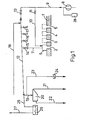
- the furnace ceiling of the coke oven battery is denoted by 1.
- the filling holes 2 to 5 are located in this.
- the suction hood 6 of the filling carriage (not shown in detail) is located above one of the filling holes.
- this is the filling hole 2, while the position of the suction hood 6 above the filling holes 3 to 5 is indicated by broken lines.
- the filling gas which collects under the suction hood 6 during the filling process has approximately the following composition:
- This gas is withdrawn together with any air as well as partially burned filling gas and flue gas from the exhaust hood 6 via line 7.
- the total amount of flue gas added in this case must be approx. 15 Nm3 flue gas per Nm3 fill gas.
- the required flue gas is drawn off from the waste heat duct of the coke oven battery by means of the blower 8 via line 9. However, it could possibly also be produced in a separate smoke gas generator 28.
- the line 10 branches off from the line 9 and leads to the suction hood 6, so that the flue gas can be admixed to the filling gas to the extent necessary under the suction hood 6 if the valve 11 is in the appropriate position.
- the line 9 also has a connection to the filling gas line 12 , so that the flue gas can only be admixed to the filling gas in the filling gas line 12 when the valve 13 is in the appropriate position.
- the valves 11 and 13 can also be regulated in such a way that flue gas is added both in the suction hood 6 and in the filling gas line 12.
- the filling gas line 12 is in this case, as indicated in the figure, designed as a so-called docking line and provided with the connecting pieces 14 to 17, which are in a corresponding position above the filling holes 2 to 5, so that the suction hood 6 in each Position of the filling car finds a corresponding connection piece in the filling gas line 12.
- This can be a known construction with a scraper belt conveyor, so that the so-called thick tar is discharged on the upper part of the thick tar separator 20 and can be drawn off via the line 21.
- the rinse water and the remaining tar meanwhile reach the condensate deep tank (not shown) of the coke oven gas treatment process via line 22.
- the rinsing water can then be returned in a manner known per se to the coke oven template (not shown) and is thus available for re-filling on the filling gas line 12.
- the filling gas / flue gas mixture largely freed of the tar and coal-containing impurities is meanwhile via the Line 23 withdrawn.
- This gas mixture is mixed during the filling process with a temperature of approx. 70 ° C to the raw coke oven gas behind the coke oven gas supply. If the normally required temperature between 40 and 70 ° C. has not already been set when entering line 23, the temperature of the gas mixture can be reduced accordingly in a cooling device, not shown.
- the throttle valve 24 is arranged in the line 23 and is closed during the filling pauses, that is to say the times in which the filling process is interrupted and the filling truck is transported from one filling hole to the other. So that the inert gas pressure in the system is maintained during this time, there is no interruption in the flue gas supply during the filling pauses. During this time, the gas from the filling gas line 12 rather reaches the immersion pot 26 via the line piece 25 and can be drawn off from there via the line 27 into the waste heat duct and the chimney (not shown).
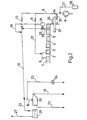
- the furnace top of the coke oven battery is again designated 1.
- the Filling holes 2 to 5 arranged.
- the suction hood 6 of the filling vehicle is located above one of the filling holes. In the illustration in FIG. 2, this is the filling hole 2.
- the filling hole 2 approximately 5 to 15 Nm 3 of dry filling gas escape during the filling process. In this case, however, the filling gas is withdrawn via the existing riser pipe 29, which is provided with a switching device 30. This is set during the withdrawal of the filling gases so that they cannot get into the coke oven gas receiver 31, but rather flow via line 32 to the filling gas line 12.
- the flue gas required for the inerting of the filling gases is also drawn off from the waste heat duct (not shown) of the coke oven battery by means of the blower 8 via the line 9. If necessary, however, it could also be produced in a separate flue gas generator 28 and - fed via line 33 into line 9. From this line 34 branches off, through which, when the valve is in the appropriate position, flue gas can reach the furnace chamber via the leveling door 36.
- the reference numeral 37 marks the leveling bar. Additional flue gas can be withdrawn via line 10 when the valve 11 is in the appropriate position and thus passes into the suction hood 6 of the filling truck, so that the necessary flue gas overpressure is set there, by which unnecessary air penetration into the suction hood 6 is avoided during the filling process .
- the line 9 also has a connection to the filling gas line 12, so that the flue gas can only be admixed to the filling gas in the filling gas line 12 if the valve 13 is in the appropriate position.
- the flue gas addition to the individual feed points can be distributed to the desired extent by a corresponding position of the valves 35, 11 and 13 or regulate.
- the amount of flue gas added in this case must be approximately 15 Nm 3 flue gas per Nm 3 filling gas.
- the filling gas that collects in the gas collection chamber of the coke oven battery during the filling process is drawn off from the gas collection chamber of the coke oven chamber together with any air as well as partially burned filling gas and flue gas via the riser pipe 29.
- the gas mixture reaches the filling gas line 12 via the line 32.
- the line 32 is arranged in a stationary manner and represents a fixed connection between the riser pipe 29 and the filling gas line 12.
- the filling gases are drawn off via an additional opening 38 in the furnace ceiling 1, this opening 38 being directly connected to the filling gas line 12 via the valve 39 and the line 40. While the filling gases are being drawn off via the opening 38 and the line 40, the coke oven gas supply 31 is shut off by actuating the switching device 30, so that no filling gases can get into the coke oven gas supply 31.
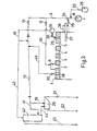
- the embodiment in FIG. 3 also relates to a process variant in which the filler gas / flue gas mixture withdrawn from the filler gas line 12 is first subjected to an aftertreatment in the form of washing with rinsing water from the coke oven gas receiver 31 before it is added to the raw coke oven gas.
- the gas mixture from the filling gas line 12 passes through line 41 into the washer 42, which it passes through from bottom to top.
- 42 washing water in an amount of 5 to 10 liters / Nm filling gas / flue gas mixture is added to the washer.
- the rinse water is supplied through line 43, which branches off from line 18.
- the washer 42 can be provided with conventional internals, the aftertreated and cleaned gas mixture being drawn off at the top of the washer 42 and reaching the raw gas stream behind the coke oven gas receiver 31 via line 23.
- the rinsing water flowing out of the washer 42 and loaded with the contaminants separated from the gas flows in the meantime via the line 44 into the thick tar separator 20, in which it is combined with the tar and coal-containing rinsing water flowing in via the connecting piece 19 from the filling gas line 12.
- the further treatment in the thick tar separator 20 then takes place in the manner already described, so that the thick tar and the flushing water and the remaining tar are drawn off via the line 21 and the line 22.
- the remaining treatment of the filling gas also corresponds to the method of operation described in connection with FIG. 1.
- the dip pot 26 shown in FIGS. 1 and 2 can also be connected downstream and the throttle valve 24 can be arranged in the line 23, so that the flue gas supply does not have to be interrupted in this case either during the filling break.
- the method according to the invention makes it possible to carry out the filling gas treatment using the existing facilities of the coke oven gas treatment process to the greatest possible extent.
- the installation and operating costs are extraordinarily low, the method according to the invention being characterized at the same time by high operational reliability and environmental friendliness.
Landscapes
- Chemical & Material Sciences (AREA)
- Engineering & Computer Science (AREA)
- Oil, Petroleum & Natural Gas (AREA)
- Chemical Kinetics & Catalysis (AREA)
- General Chemical & Material Sciences (AREA)
- Materials Engineering (AREA)
- Organic Chemistry (AREA)
- Coke Industry (AREA)
- Industrial Gases (AREA)
Applications Claiming Priority (4)
| Application Number | Priority Date | Filing Date | Title |
|---|---|---|---|
| DE2942962 | 1979-10-24 | ||
| DE19792942962 DE2942962A1 (de) | 1979-10-24 | 1979-10-24 | Verfahren zum betrieb einer koksofenbatterie |
| DE19792949016 DE2949016A1 (de) | 1979-12-06 | 1979-12-06 | Verfahren zum betrieb einer koksofenbatterie |
| DE2949016 | 1979-12-06 |
Publications (2)
| Publication Number | Publication Date |
|---|---|
| EP0027872A1 true EP0027872A1 (fr) | 1981-05-06 |
| EP0027872B1 EP0027872B1 (fr) | 1983-01-12 |
Family
ID=25781654
Family Applications (1)
| Application Number | Title | Priority Date | Filing Date |
|---|---|---|---|
| EP80105079A Expired EP0027872B1 (fr) | 1979-10-24 | 1980-08-27 | Procédé de mise en oeuvre d'une batterie de fours à coke |
Country Status (5)
| Country | Link |
|---|---|
| US (1) | US4283253A (fr) |
| EP (1) | EP0027872B1 (fr) |
| AU (1) | AU531564B2 (fr) |
| CA (1) | CA1162162A (fr) |
| DE (1) | DE3061632D1 (fr) |
Families Citing this family (2)
| Publication number | Priority date | Publication date | Assignee | Title |
|---|---|---|---|---|
| DE3150657A1 (de) * | 1981-12-21 | 1983-06-30 | Dr. C. Otto & Comp. Gmbh, 4630 Bochum | "rohrstueck zur fuellgasabsaugung an verkokungsoefen" |
| DE19729032C1 (de) * | 1997-07-08 | 1999-02-11 | Dmt Gmbh | Vorrichtung zum Abdichten einer Planiertüröffnung einer Koksofenkammer |
Citations (3)
| Publication number | Priority date | Publication date | Assignee | Title |
|---|---|---|---|---|
| DE801274C (de) * | 1949-01-01 | 1950-12-28 | Koppers Gmbh Heinrich | Vorrichtung zum Absaugen der Fuellgase von OEfen zur Erzeugung von Gas und Koks |
| DE2710672A1 (de) * | 1976-03-19 | 1977-09-29 | Otto & Co Gmbh Dr C | Batterie waagerechter verkokungsofenkammern und verfahren zum betrieb derselben |
| US4157940A (en) * | 1976-03-19 | 1979-06-12 | Dr. C. Otto & Comp. G.M.B.H. | Method for operating a battery of horizontal coke ovens |
Family Cites Families (9)
| Publication number | Priority date | Publication date | Assignee | Title |
|---|---|---|---|---|
| GB1460735A (en) * | 1973-04-05 | 1977-01-06 | Carves Simon Ltd | Coking ovens |
| ZA742128B (en) * | 1973-04-26 | 1975-11-26 | Carves Simon Ltd | Improvements in or relating to coking ovens |
| US4010079A (en) * | 1973-08-30 | 1977-03-01 | Wilputte Corporation | Coke oven charging gas cleaning and collecting apparatus and process |
| GB1546572A (en) * | 1975-08-08 | 1979-05-23 | British Steel Corp Chemical Lt | Methdod of emission control during charging of coke ovens |
| DE2600130C2 (de) * | 1976-01-03 | 1982-07-22 | Carl Still Gmbh & Co Kg, 4350 Recklinghausen | Verfahren zur Reinhaltung des Kreislauf-Berieselungswassers für die Steigerohre von Verkokungsöfen |
| FR2338988A1 (fr) * | 1976-01-22 | 1977-08-19 | Lorraine Houilleres | Procede de separation des poussieres goudronneuses de gaz de fours a coke |
| DE2632092A1 (de) * | 1976-07-16 | 1978-01-26 | Otto & Co Gmbh Dr C | Verfahren zum kuehlen von gasen, die feststoffe, teer und naphthalin enthalten |
| GB1538859A (en) * | 1976-07-22 | 1979-01-24 | British Steel Corp | Collection of coke oven by products |
| GB1540305A (en) * | 1977-11-30 | 1979-02-07 | Carves Ltd O | Coking ovens |
-
1980
- 1980-08-27 EP EP80105079A patent/EP0027872B1/fr not_active Expired
- 1980-08-27 DE DE8080105079T patent/DE3061632D1/de not_active Expired
- 1980-09-18 US US06/188,281 patent/US4283253A/en not_active Expired - Lifetime
- 1980-09-29 CA CA000361233A patent/CA1162162A/fr not_active Expired
- 1980-10-21 AU AU63537/80A patent/AU531564B2/en not_active Ceased
Patent Citations (3)
| Publication number | Priority date | Publication date | Assignee | Title |
|---|---|---|---|---|
| DE801274C (de) * | 1949-01-01 | 1950-12-28 | Koppers Gmbh Heinrich | Vorrichtung zum Absaugen der Fuellgase von OEfen zur Erzeugung von Gas und Koks |
| DE2710672A1 (de) * | 1976-03-19 | 1977-09-29 | Otto & Co Gmbh Dr C | Batterie waagerechter verkokungsofenkammern und verfahren zum betrieb derselben |
| US4157940A (en) * | 1976-03-19 | 1979-06-12 | Dr. C. Otto & Comp. G.M.B.H. | Method for operating a battery of horizontal coke ovens |
Also Published As
| Publication number | Publication date |
|---|---|
| US4283253A (en) | 1981-08-11 |
| AU6353780A (en) | 1981-04-30 |
| DE3061632D1 (en) | 1983-02-17 |
| EP0027872B1 (fr) | 1983-01-12 |
| CA1162162A (fr) | 1984-02-14 |
| AU531564B2 (en) | 1983-08-25 |
Similar Documents
| Publication | Publication Date | Title |
|---|---|---|
| DE3315738C2 (de) | Verfahren und Einrichtung zum Entstauben von Kokereiemissionen | |
| EP0606573B1 (fr) | Procédé pour refroidir et purifier du gaz contenant de fines particules, spécialement gaz de geulart ou d'un générateur de gaz et installation à cette fin | |
| DE3328702A1 (de) | Verfahren und vorrichtung zum loeschen von gluehendem koks | |
| EP0728713B1 (fr) | Procédé d'utilisation de matériaux de déchets pour la fabrication de ciment | |
| DE2142052A1 (de) | Einrichtung und Verfahren zur Her stellung verwertbarer Stoffe aus Abfall stoffen | |
| DE3307848A1 (de) | Verfahren zur nachverbrennung und reinigung von prozessabgasen | |
| DE2915330A1 (de) | Verfahren und anlage fuer die nassloeschung von koks | |
| EP0064617A2 (fr) | Procédé et dispositif pour l'exploitation d'une installation de fours à coke | |
| DE3328373A1 (de) | Verfahren und anlage zur direkten erzeugung von eisenschwammpartikeln und fluessigem roheisen aus stueckigem eisenerz | |
| EP1201731A1 (fr) | Procédé de gazéification en lit fluidisé de solides contenant du carbone et installation de gazéification | |
| EP0183677A3 (fr) | Procédé et appareil pour la réduction directe de minerais de fer et leur fusion dans un gazogène | |
| DD227985A5 (de) | Verfahren zur aufarbeitung von schwermetallhaltigen rueckstaenden der chemischen industrie | |
| DE2646865A1 (de) | Verfahren zur reinigung und kuehlung von staubfoermige verunreinigungen enthaltenden partialoxydationsgasen | |
| DE2944989C3 (fr) | ||
| DE4412004A1 (de) | Verfahren zum Vergasen von Abfallstoffen in der zirkulierenden Wirbelschicht | |
| EP0027872B1 (fr) | Procédé de mise en oeuvre d'une batterie de fours à coke | |
| DE3006570A1 (de) | Vorrichtung und verfahren zum koksloeschen | |
| DE3714749C2 (fr) | ||
| DE2942962A1 (de) | Verfahren zum betrieb einer koksofenbatterie | |
| DE897310C (de) | Verfahren und Vorrichtung zur Vergasung von Brennstoffen | |
| DE19614482C1 (de) | Anlage zum Naßlöschen von heißem Koks im Zuge der Verkokung von Steinkohle und Verfahren zum Betrieb der Anlage | |
| DE2949016A1 (de) | Verfahren zum betrieb einer koksofenbatterie | |
| DE2804934C2 (de) | Vorrichtung zur Trennung von Gasen und Feststoffen bei der Verkokung von Kohle | |
| DE19602321A1 (de) | Verfahren und Verwertung von Reststoffen bei der Zementherstellung | |
| DE3730749C2 (de) | Verfahren und Vorrichtung zum emissionsfreien Löschen von Koks |
Legal Events
| Date | Code | Title | Description |
|---|---|---|---|
| PUAI | Public reference made under article 153(3) epc to a published international application that has entered the european phase |
Free format text: ORIGINAL CODE: 0009012 |
|
| AK | Designated contracting states |
Designated state(s): BE DE FR GB NL SE |
|
| 17P | Request for examination filed |
Effective date: 19810921 |
|
| GRAA | (expected) grant |
Free format text: ORIGINAL CODE: 0009210 |
|
| AK | Designated contracting states |
Designated state(s): BE DE FR GB NL SE |
|
| ET | Fr: translation filed | ||
| REF | Corresponds to: |
Ref document number: 3061632 Country of ref document: DE Date of ref document: 19830217 |
|
| PGFP | Annual fee paid to national office [announced via postgrant information from national office to epo] |
Ref country code: FR Payment date: 19840713 Year of fee payment: 5 |
|
| PGFP | Annual fee paid to national office [announced via postgrant information from national office to epo] |
Ref country code: DE Payment date: 19840919 Year of fee payment: 5 |
|
| PGFP | Annual fee paid to national office [announced via postgrant information from national office to epo] |
Ref country code: SE Payment date: 19840930 Year of fee payment: 5 Ref country code: BE Payment date: 19840930 Year of fee payment: 5 |
|
| PG25 | Lapsed in a contracting state [announced via postgrant information from national office to epo] |
Ref country code: SE Effective date: 19870828 |
|
| PGFP | Annual fee paid to national office [announced via postgrant information from national office to epo] |
Ref country code: NL Payment date: 19870831 Year of fee payment: 8 |
|
| BERE | Be: lapsed |
Owner name: KRUPP-KOPPERS G.M.B.H. Effective date: 19870831 |
|
| PG25 | Lapsed in a contracting state [announced via postgrant information from national office to epo] |
Ref country code: FR Free format text: LAPSE BECAUSE OF NON-PAYMENT OF DUE FEES Effective date: 19880429 |
|
| PG25 | Lapsed in a contracting state [announced via postgrant information from national office to epo] |
Ref country code: DE Effective date: 19880503 |
|
| GBPC | Gb: european patent ceased through non-payment of renewal fee | ||
| REG | Reference to a national code |
Ref country code: FR Ref legal event code: ST |
|
| PG25 | Lapsed in a contracting state [announced via postgrant information from national office to epo] |
Ref country code: GB Free format text: LAPSE BECAUSE OF NON-PAYMENT OF DUE FEES Effective date: 19881118 |
|
| PG25 | Lapsed in a contracting state [announced via postgrant information from national office to epo] |
Ref country code: NL Effective date: 19890301 |
|
| NLV4 | Nl: lapsed or anulled due to non-payment of the annual fee | ||
| PG25 | Lapsed in a contracting state [announced via postgrant information from national office to epo] |
Ref country code: BE Effective date: 19890831 |
|
| EUG | Se: european patent has lapsed |
Ref document number: 80105079.0 Effective date: 19880707 |
|
| PLBE | No opposition filed within time limit |
Free format text: ORIGINAL CODE: 0009261 |
|
| STAA | Information on the status of an ep patent application or granted ep patent |
Free format text: STATUS: NO OPPOSITION FILED WITHIN TIME LIMIT |