EP0027880A2 - Haushalt-Getränkeautomat - Google Patents
Haushalt-Getränkeautomat Download PDFInfo
- Publication number
- EP0027880A2 EP0027880A2 EP80105399A EP80105399A EP0027880A2 EP 0027880 A2 EP0027880 A2 EP 0027880A2 EP 80105399 A EP80105399 A EP 80105399A EP 80105399 A EP80105399 A EP 80105399A EP 0027880 A2 EP0027880 A2 EP 0027880A2
- Authority
- EP
- European Patent Office
- Prior art keywords
- household
- beverage dispenser
- containers
- open
- carbon dioxide
- Prior art date
- Legal status (The legal status is an assumption and is not a legal conclusion. Google has not performed a legal analysis and makes no representation as to the accuracy of the status listed.)
- Granted
Links
Images



Classifications
-
- B—PERFORMING OPERATIONS; TRANSPORTING
- B67—OPENING, CLOSING OR CLEANING BOTTLES, JARS OR SIMILAR CONTAINERS; LIQUID HANDLING
- B67D—DISPENSING, DELIVERING OR TRANSFERRING LIQUIDS, NOT OTHERWISE PROVIDED FOR
- B67D1/00—Apparatus or devices for dispensing beverages on draught
- B67D1/0042—Details of specific parts of the dispensers
- B67D1/0043—Mixing devices for liquids
- B67D1/0044—Mixing devices for liquids for mixing inside the dispensing nozzle
- B67D1/0046—Mixing chambers
-
- B—PERFORMING OPERATIONS; TRANSPORTING
- B67—OPENING, CLOSING OR CLEANING BOTTLES, JARS OR SIMILAR CONTAINERS; LIQUID HANDLING
- B67D—DISPENSING, DELIVERING OR TRANSFERRING LIQUIDS, NOT OTHERWISE PROVIDED FOR
- B67D1/00—Apparatus or devices for dispensing beverages on draught
- B67D1/0015—Apparatus or devices for dispensing beverages on draught the beverage being prepared by mixing at least two liquid components
- B67D1/0021—Apparatus or devices for dispensing beverages on draught the beverage being prepared by mixing at least two liquid components the components being mixed at the time of dispensing, i.e. post-mix dispensers
-
- B—PERFORMING OPERATIONS; TRANSPORTING
- B67—OPENING, CLOSING OR CLEANING BOTTLES, JARS OR SIMILAR CONTAINERS; LIQUID HANDLING
- B67D—DISPENSING, DELIVERING OR TRANSFERRING LIQUIDS, NOT OTHERWISE PROVIDED FOR
- B67D1/00—Apparatus or devices for dispensing beverages on draught
- B67D1/08—Details
- B67D1/0801—Details of beverage containers, e.g. casks, kegs
- B67D2001/0812—Bottles, cartridges or similar containers
-
- B—PERFORMING OPERATIONS; TRANSPORTING
- B67—OPENING, CLOSING OR CLEANING BOTTLES, JARS OR SIMILAR CONTAINERS; LIQUID HANDLING
- B67D—DISPENSING, DELIVERING OR TRANSFERRING LIQUIDS, NOT OTHERWISE PROVIDED FOR
- B67D2210/00—Indexing scheme relating to aspects and details of apparatus or devices for dispensing beverages on draught or for controlling flow of liquids under gravity from storage containers for dispensing purposes
- B67D2210/00002—Purifying means
- B67D2210/00005—Filters
-
- B—PERFORMING OPERATIONS; TRANSPORTING
- B67—OPENING, CLOSING OR CLEANING BOTTLES, JARS OR SIMILAR CONTAINERS; LIQUID HANDLING
- B67D—DISPENSING, DELIVERING OR TRANSFERRING LIQUIDS, NOT OTHERWISE PROVIDED FOR
- B67D2210/00—Indexing scheme relating to aspects and details of apparatus or devices for dispensing beverages on draught or for controlling flow of liquids under gravity from storage containers for dispensing purposes
- B67D2210/00028—Constructional details
- B67D2210/00031—Housing
Definitions
- the innovation is based on a household beverage vending machine with exchangeable storage containers for beverage concentrates, carbon dioxide containers or the like, as well as with electrical and fluidic devices for portioned removal of the concentrate, mixing with water and feeding the mixture to an output station.
- vending machines of this type can indeed be operated from the front of the device, as far as the switching on of the device, the selection of the beverage and the removal of the selected beverage are concerned.
- the replacement of the storage containers, the replacement of the empty carbon dioxide bottle and the like is not readily possible only from the front of the device in these known vending machines.
- Such Ge automatic watering machines cannot be used as so-called built-in devices, in which at least a large part of the side surfaces of the device is enclosed by furniture, for example built-in kitchen furniture.
- built-in devices have a filling capacity of approximately 1,500 portions, the vending machine needs to be refilled from time to time.
- the entire device would then have to be removed from the installed position each time, which is not reasonable for the consumer.
- the innovation is based on the task of designing a domestic drinks machine of the type mentioned in such a way that it can be fully operated from the front and thus enables its use as a built-in appliance.
- this object is achieved in that a space for all detachable or replaceable functional parts such as storage containers and carbon dioxide containers is provided in the device housing, preferably above the feeding and mixing station, and is open to the front of the device and can optionally be covered by a removable or swiveling front panel.
- each interchangeable storage container for the beverage concentrate, from which the individual concentrate portions are removed is provided with a metering valve for this purpose, which is opened electromagnetically for portion removal.
- each storage container is assigned an annular coil which is fixed to the device and into which the storage container with its metering valve must be set from above. With excitement of the Ring coil, the metering valve is opened.
- the storage container of which is provided in the aforementioned manner with metering valves which can be actuated by electromagnetic means
- full front operability is made possible with a very small device height
- the electromagnetic actuating device is made of there is a U-shaped magnet yoke open towards the front of the device in connection with a magnet coil arranged thereon. It is advantageous if the legs of the U-shaped magnetic yoke are surrounded by protective walls towards the front of the device, which delimit a niche open at the front for adjusting the storage container with its metering valve.
- the household beverage machine shown schematically in FIGS. 1 to 4 has a box-like device housing 1, for example made of plastic material, of which the device front is shown in FIG. 1.
- the device housing 1 On the back of the device, the device housing 1 is provided with a lower indentation 2, in the area in which electrical connections or water-technical connections (not shown further) can be located.
- the front of the device As shown in FIG. 1 in connection with FIG. 4, the front of the device is open in the area of the widths a and b to the front of the device and is separated in height by an intermediate floor 3 into two superimposed rooms with the height c and d.
- the lower space in FIG. 1 with the width b and the height d forms a removal space 4, on the bottom 5 of which a drinking glass 6 is placed.
- a beverage mixing channel 7 with an inclined floor is detachably fastened in guide strips 8.
- the upper space 9 with the width a and the depth c and the lower space 4 are separated from the rest of the interior of the device by a trough-like shell body 10 with a rear wall 11 which is molded in approximately half the height and forms the intermediate floor 3 and which is in the upper space area , has a further bulge 13 forming a space 12 accessible from the front.
- the shell body 10 also has horizontal shell walls 14 and 15.
- the shell body 10 has according to the rooms 4 and 9 graded widths a and b and a height that results from the addition of the partial heights c and d. As indicated in FIG.
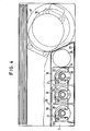
- FIG. 1 in connection with FIG. 4, an electromagnetically actuable actuating device is assigned to each storage container 18 at the level of the metering valves.
- Each actuating device consists of an essentially U-shaped magnetic yoke 21 and a magnetic coil 22 arranged thereon.
- the protective walls form open niches 25 on the front, into which the storage containers 18 with their metering valves 19 can be inserted horizontally from the front of the device.
- a carbon dioxide container is designated by 26, which can be adjusted laterally next to the storage containers 18 into the upper space 9 within the shell body 10 and can be connected to corresponding gas lines.
- the front open cutout of the device housing 1 in the area of the upper room 4 can be covered by a front panel 28, which can be folded upwards, for example, about the pivot point 27, which front panel is trans can be parent or can be provided on the outer surface with corresponding references to the contents of the storage container 18.
- each of the keys lying one below the other in the exemplary embodiment 4 is assigned to one of the storage containers 18 which contain different syrups, the fourth key serving to provide a pure soda drink. If one of the buttons assigned to the storage containers is actuated, carbonized water flows from a water container (not shown) that is provided with a cooling device into the mixing trough 7 is emitted into the mixing trough 7, which mixes there with the carbonized water and flows into the drinking glass 6.
- FIG. 5 shows some installation options for the explained domestic drinks machine.
- the device 1 is only indicated schematically in its outlines.
- a worktop 31 has a row of cupboards 32 at a distance from the worktop.
- FIG. 5 shows three different ways of attaching or installing the drinks machine to or in this row of cupboards.
- the vending machine is attached directly to the lower boundary of the cabinet row 32 at a distance from the worktop 31.
- the drinks machine is only installed with its upper part in the cabinet row 32, so that practically only the room 4, ie the mixing and dispensing station of the device and the operating and display elements 29 located at the same height below the Stand out cabinet row 32 and are freely accessible there at working height.
- the entire vending machine is installed in the cabinet row 32 and can be concealed by a cabinet door.
Landscapes
- Devices For Dispensing Beverages (AREA)
- Beverage Vending Machines With Cups, And Gas Or Electricity Vending Machines (AREA)
Abstract
Description
- Die Neuerung geht aus von einem Haushalt-Getränkeautomatemit auswechselbaren Vorratsbehältern für Getränkekonzentrate, Kohlendioxidbehälter oder dergleichen sowie mit elektrischen und strömungstechnischen Einrichtungen für die portionierte Konzentratentnahme, die Vermischung mit Wasser und die Zuführung des Gemisches zu einer Ausgabestation.
- Derartige bekannte Getränkeautomaten sind zwar von der Gerätefrontseite her bedienbar, was die Einschaltung des Geräts,die Auswahl des Getränkes und die Entnahme des ausgewählten Getränkes angeht. Jedoch ist das Auswechseln der Vorratsbehälter, das Austauschen der leeren Kohlendioxidflasche und dergleichen ausschließlich von der Gerätefrontseite her bei diesen bekannten Getränkeautomaten nicht ohne weiteres möglich. Dies hat zur Folge, daß derartige Getränkeautomaten nicht als sogenannte Einbaugeräte verwendbar sind, bei denen zumindest ein Großteil der Geräte-Seitenflächen von Möbeln, z.B. von Einbau-Küchenmöbeln, umschlossen ist. Obwohl derartige Getränkeautomaten eine Füllkapazität von annähernd 1500 Getränkeportionen haben, ist doch von Zeit zu Zeit ein Nachfüllen des Automaten erforderlich. Bei der Verwendung des vorgenannten bekannten Automaten als Einbaugerät müßte dann jedesmal das gesamte Gerät aus der Einbaulage entfernt werden, was für den Verbraucher nicht zumutbar ist.
- Der Neuerung liegt die Aufgabe zugrunde, einen Haushalt-Getränkeautomaten der eingangs genannten Art so auszugestalten, daß volle Frontbedienbarkeit gegeben ist und damit dessen Verwendung als Einbaugerät ermöglicht wird.
- Diese Aufgabe wird gemäß der Neuerung dadurch gelöst, daß im Gerätegehäuse, vorzugsweise oberhalb der Aufgabe- und Mischstation ein zur Gerätefrontseite hin offener und gegebenenfalls durch eine abnehmbare oder schwenkbare Frontblende abdeckbarer Raum für alle lösbaren bzw. auswechselbaren Funktionsteile wie Vorratsbehälter, Kohlendioxidbehälter vorgesehen ist.
- Bei den bekannten Getränkeautomaten der vorgenannten Art ist jeder auswechselbare Vorratbsbehälter für das Getränkekonzentrat, aus dem die einzelnen Konzentratportionen entnommen werden,zu diesem Zweck mit einem Dosierventil versehen, das auf elektromagnetischem Wege zur Portionsentnahme geöffnet wird. Als Betätigungsvorrichtung hierfür ist jedem Vorratsbehälter eine gerätefest angeordnete Ringspule zugeordnet, in welchehe der Vorratsbehälter mit seinem Dosierventil von oben her eingestellt werden muß. Mit Erregung der Ringspule wird das Dosierventil geöffnet.
- Gemäß einer besonders vorteilhaften Ausgestaltung der Erfindung wird bei einem Getränkeautomaten, dessen Vorratsbehälter in der vorgenannten Weise mit Dosierventilen versehen ist, die auf elektromagnetischem Wege betätigt werden können, eine volle Frontbedienbarkeit bei sehr knapp bemessener Geräte-Bauhöhe ermöglicht, dadurch, daß die elektromagnetische Betätigungsvorrichtung aus einem zur Gerätefrontseite hin offenen, U-förmigen Magnetjoch in Verbindung mit einer darauf angeordneten Magnetspule besteht. Dabei ist es vorteilhaft, wenn die Schenkel des U-förmigen Magnetjochs zur Gerätefrontseite hin von Schutzwänden umgeben sind, die eine frontseitig offene Nische zum Einstellen des Vorratsbehälters mit seinem Dosierventil begrenzen. Durch die neuerungsgemäße Ausgestaltung wird nicht nur eine optimale Frontbedienbarkeit erreicht, sondern es werden auch die kosten für die Betätigungsvorrichtung gegenüber bekannten Ausführungen infolge des wesentlich verminderten Kupferanteiles erheblich gesenkt.
- Weitere vorteilhafte Einzelheiten der Feuerung ergeben sich aus dem in der Zeichnung dargestellten und nachstehend beschriebenen Ausführungsbeispiel.
- Es zeigt
- Fig. 1 eine Draufsicht auf den nur schematisch dargestellten neuerungsgemäßen Haushalt-Getränkeautomat,
- Fig. 2 und 3 zwei unterschiedliche Schnitt-Seitenansichten des Automaten gemäß Figur 1,
- Fig. 4 eine zum Teil in Schnittansicht dargestellte Draufsicht auf den Haushalt-Getränkeautomaten gemäß den vorhergehenden Figuren,
- Fig. 5 eine Draufsicht auf einen schematisch dargestellten Einbau-Küchenblock in Verbindung mit dem neuerungsgemäßen Haushalt-Getränkeautomaten.
- Der.in den Figuren 1 bis 4 schematisch dargestellte Haushalt-Getränkeautomat besitzt ein kastenartiges Gerätegehäuse 1 z.B. aus Kunststoffmaterial, von dem in Figur 1 die GeräteFrontseite dargestellt ist. An der Geräterückseite ist das Gerätegehäuse 1 mit einer unteren Einbuchtung 2 versehen, im Bereich welcher sich nicht weiter dargestellte elektrische Anschlüsse oder wassertechnische Anschlüsse befinden können. Wie Figur 1 in Verbindung mit Figur 4 zeigt, ist die Gerätefrontseite im Bereich der Breite a und b zur Gerätefrontseite hin offen und höhenmäßig durch einen Zwischenboden 3 in zwei übereinanderliegende Räume mit der Höhe c und d getrennt. Der in Figur 1 untere Raum mit der Breite b und der Höhe d bildet einen Entnahmeraum 4, auf dessen Boden 5 ein Trinkglas 6 abgestellt ist. An der Unterseite des Zwischenbodens 3 ist, wie Figur 1 in Verbindung mit Figur 2 zeigt, ein Getränke-Mischkanal 7 mit geneigtem Boden in Führungsleisten 8 lösbar befestigt. Der obere Raum 9 mit der Breite a und der Tiefe c sowie der untere Raum 4 sind vom übrigen Geräteinnenraum getrennt durch einen wannenartigen Schalenkörper 10 mit einer Rückwand 11, die etwa in halber Höhe eingeformt ist und den Zwischenboden 3 bildet und die im oberen Raumbereich eine, einen weiteren von der Frontseite her zugänglichen Raum 12 bildende Ausbuchtung 13 besitzt. Der Schalenkörper 10 besitzt ferner waagerechte Schalenwände 14 und 15. Der Schalenkörper 10 besitzt entsprechend den Räumen 4 und 9 abgestufte Breiten a und b sowie eine Höhe, die sich aus der Addition der Teilhöhen c und d ergibt. Wie in Figur 3 angedeutet, befindet sich im Geräteraumbereich mit der Breite e (Fig.1) übereinander ein Verdichter 16 einer Kühleinrichtung an sich bekannter Art sowie ein ebenfalls an sich bekannter Carbonisator 17. In den Raum 9 senkrecht einstellbar sind beim Ausführungsbeispiel 3 Getränkekonzentrat-Vorratsbehälter 18, die an den Unterseiten Dosierventile 19 besitzen. Diese Vorratsbehälter 18 stützen sich mit stufenförmigen Ansätzen 20 auf der oberen Begrenzung der in mittlerer Höhe angeordneten Einbuchtung des Schalenkörpers 10 ab. Die Mischrinne 7 ist nach oben, also zu den Dosierventilen 19 hin offen. Wie Figur 1 in Verbindung mit Fig. 4 zeigt, ist in Höhe der Dosierventile jedem Vorratsbehälter 18 eine elektromagnetisch betätigbare Betätigungsvorrichtung gerätefest zugeordnet. Jede Betätigungsvorrichtung besteht aus einem im wesentlichen U-förmigen Magnetjoch 21 und einer darauf angeordneten Magnetspule 22. Wie insbesondere aus Figur 4 hervorgeht, sind die freien Schenkel des U-förmigen Magnetjochs 21 umgeben von Schutzwänden 23 eines Isolierstreifens 24, der Teil des Schalenkörpers 10 sein kann. Die Schutzwände bilden frontseitig offene Nischen 25, in welche die Vorratsbehälter 18 mit ihren Dosierventilen 19 horizontal von der Gerätefrontseite her einschiebbar sind.
- Mit 26 ist ein Kohlendioxidbehälter bezeichnet, der seitlich neben den Vorratsbehältern 18 in den oberen Raum 9 innerhalb des Schalenkörpers 10 einstellbar ist und an entsprechende Gasleitungen anschließbar ist.
- Aus den Figuren 2 und 4 ist zu entnehmen, daß der frontseitig offene Ausschnitt des Gerätegehäuses 1 im Bereich des oberen Raumes 4 durch eine z.B. um den Drehpunkt bei 27 nach oben hochklappbare Frontblende 28 verdeckbar ist, welche Frontblende transparent sein kann oder aber an der Außenfläche mit entsprechenden Hinweisen auf den Inhalt der Vorratsbehälter 18 versehen sein kann.
- Schließlich befinden sich an der Gerätefrontseite in Höhe der Misch- und Ausgabestation, d.h. des unteren Raumes 4 Bedienungs- und Anzeigeorgane 29 in Form einer Tastenbank. Jede der im Ausführungsbeispiel 4 untereinanderliegenden Tasten ist einem der Vorratsbehälter 18, die unterschiedliche Sirupe enthalten, zugeordnet, wobei die vierte Taste zur Bereitstellung eines reinen Sodagetränkes dient. Wird eine der den Vorratsbehältern zugeordnete Taste betätigt, so fließt aus einem nicht weiter dargestellten, mit einer Kühleinrichtung versehenen Wasserbehälter carbonisiertes Wasser in die Mischrinne 7. Kurzzeitig danach wird die Magnetspule 22 der Betätigungsvorrichtung erregt, womit aus dem Dosierventil 19 des Vorratsbehälters 18 eine vorbestimmte Konzentratmenge in die Mischrinne 7 abgegeben wird, die sich dort mit dem carbonisierten Wasser vermischt und in das Trinkglas 6 einfließt.
- Wie die Figuren verdeutlichen, sind alle Funktionsteile des Getränkeautomaten, die von Zeit zu Zeit ausgetauscht werden müssen (Vorratsbehälter 18, Kohlendioxidbehälter 26) oder aber gewartet werden müssen,z.B. das in der Ausbuchtung 13 untergebrachte Wasserfilter 50,ausschließlich von der Gerätefrontseite her zugänglich, sc daß das beschriebene Gerät vorteilhaft als Einbaugerät verwendet werden kann.
- In Figur 5 sind einige Einbaumöglichkeiten des erläuterten Haushalt-Getränkeautomaten dargestellt. Hierbei ist das Gerät 1 nur in seinen Umrissen schematisch angedeutet. Oberhalb einer Arbeitsplatte 31 befindet sich mit Abstand zur Arbeitsplatte eine Schrankzeile 32. Figur 5 zeigt drei verschiedene Möglichkeiten des An- bzw. Einbaues des Getränkeautomaten an bzw. in diese Schrankzeile. In Figur 5-rechts ist der Getränkeautomat unmittelbar an die untere Begrenzung der Schrankzeile 32 mit Abstand zur Arbeitsplatte 31 angesetzt. Bei der in Figur 5 mittleren Variante ist der Getränkeautomat nur mit seinem oberen Teil in die Schrankzeile 32 eingebaut, sodaß praktisch nur mehr der Raum 4, d.h. die Misch- und Ausgabestation des Gerätes sowie die in gleicher Höhe befindlichen Bedienungs- und Anzeigeorgane 29 unterhalb der Schrankzeile 32 herausragen und dort in Arbeitshöhe frei zugriffsbereit sind. Dagegen ist bei der in Figur 5 linken Variante der gesamte Getränkeautomat in die Schrankzeile 32 eingebaut und durch eine Schranktür verdeckbar.
Claims (6)
Applications Claiming Priority (2)
| Application Number | Priority Date | Filing Date | Title |
|---|---|---|---|
| DE7930729U | 1979-10-30 | ||
| DE19797930729U DE7930729U1 (de) | 1979-10-30 | 1979-10-30 | Haushalt-getraenkeautomat |
Publications (3)
| Publication Number | Publication Date |
|---|---|
| EP0027880A2 true EP0027880A2 (de) | 1981-05-06 |
| EP0027880A3 EP0027880A3 (en) | 1982-09-15 |
| EP0027880B1 EP0027880B1 (de) | 1986-11-26 |
Family
ID=6708680
Family Applications (1)
| Application Number | Title | Priority Date | Filing Date |
|---|---|---|---|
| EP80105399A Expired EP0027880B1 (de) | 1979-10-30 | 1980-09-10 | Haushalt-Getränkeautomat |
Country Status (4)
| Country | Link |
|---|---|
| US (1) | US4496080A (de) |
| EP (1) | EP0027880B1 (de) |
| CA (1) | CA1151605A (de) |
| DE (2) | DE7930729U1 (de) |
Cited By (8)
| Publication number | Priority date | Publication date | Assignee | Title |
|---|---|---|---|---|
| EP0080253A3 (en) * | 1981-11-12 | 1983-09-07 | The Coca-Cola Comapny | Post-mix beverage dispenser |
| US4493441A (en) * | 1981-11-12 | 1985-01-15 | The Coca-Cola Company | Portable post-mix beverage dispenser unit |
| EP0181450A1 (de) * | 1984-11-16 | 1986-05-21 | The Coca-Cola Company | Einrichtung zur Qualitätssicherung in einem Spender für nachträglich gemischte Getränke |
| US4679707A (en) * | 1981-06-26 | 1987-07-14 | The Coca-Cola Company | Post-mix beverage dispenser apparatus having front access for loading syrup, CO2 and water |
| US4688701A (en) * | 1981-06-26 | 1987-08-25 | The Coca-Cola Company | Self-contained portable post-mix beverage dispenser apparatus having access for manually loading syrup CO2 and water |
| WO2014159458A1 (en) * | 2013-03-14 | 2014-10-02 | Altria Client Services Inc. | Disposable beverage pod and apparatus for making a beverage |
| US9771552B2 (en) | 2014-03-12 | 2017-09-26 | Altria Client Services Llc | Flavor system and method for making sherry wine like beverages |
| US10301583B2 (en) | 2013-03-14 | 2019-05-28 | Altria Client Services Llc | Flavor system and method for making beverages |
Families Citing this family (17)
| Publication number | Priority date | Publication date | Assignee | Title |
|---|---|---|---|---|
| US4687120A (en) * | 1982-12-27 | 1987-08-18 | The Cornelius Company | Method and apparatus for dispensing cold beverage |
| US4674656A (en) * | 1984-10-22 | 1987-06-23 | The Coca-Cola Company | Agitator assembly for the refrigeration system of a beverage dispenser |
| US4703870A (en) * | 1986-07-21 | 1987-11-03 | The Cocoa-Cola Company | Water reservoir assembly for post-mix beverage dispenser |
| US5190188A (en) * | 1987-12-04 | 1993-03-02 | The Coca-Cola Company | Convertible beverage dispenser |
| JPH01153492A (ja) * | 1987-12-08 | 1989-06-15 | Sanden Corp | 可変式後混合炭酸飲料分配装置 |
| DE3940876A1 (de) * | 1989-12-11 | 1991-06-13 | Bosch Siemens Hausgeraete | Antriebsvorrichtung in einem fluessigkeitsspendenden geraet, insbesondere in einem getraenkeautomaten |
| US5353963A (en) * | 1993-06-02 | 1994-10-11 | Karma, Inc. | Post mix dispenser |
| DE19526215A1 (de) * | 1994-08-22 | 1996-02-29 | Unifontes Ag | Gerät zur Erzeugung und Abgabe verschiedener Post-Mix-Getränke sowie Verfahren zum Betrieb eines solchen Gerätes |
| US7866508B2 (en) * | 2005-09-19 | 2011-01-11 | JMF Group LLC | Beverage dispensing system and method |
| USD586880S1 (en) | 2006-11-17 | 2009-02-17 | Pur Water Purification Products Inc. | Faucet mount housing |
| USD592729S1 (en) | 2006-11-17 | 2009-05-19 | Pur Water Purification Products, Inc. | Dispenser cartridge |
| USD576250S1 (en) | 2006-11-17 | 2008-09-02 | Pur Water Purification Products, Inc. | Dispenser cartridge and pitcher |
| US7863546B2 (en) * | 2006-12-27 | 2011-01-04 | Kraft Foods Global Brands Llc | Automated preparation of infant formula and children's beverages |
| US8708197B1 (en) * | 2011-12-01 | 2014-04-29 | Kenneth L. Brewer | Portable refrigerator system |
| US9932218B2 (en) | 2016-03-04 | 2018-04-03 | BIBO Barmaid LLC | Cold beverage dispenser and cutter assembly for cold beverage dispenser |
| US9695030B2 (en) | 2014-07-22 | 2017-07-04 | BIBO Barmaid LLC | Cold beverage dispenser |
| US20180057338A1 (en) * | 2016-08-31 | 2018-03-01 | Bsh Hausgeraete Gmbh | Drink Producing Apparatus With A Decompression Chamber Chargeable With Ambient Air, Household Refrigeration Apparatus As Well As Method For Producing A Drink |
Family Cites Families (12)
| Publication number | Priority date | Publication date | Assignee | Title |
|---|---|---|---|---|
| US2583461A (en) * | 1946-08-28 | 1952-01-22 | Square Mfg Company | Beverage dispensing machine |
| US2657628A (en) * | 1947-01-09 | 1953-11-03 | Wurlitzer Co | Beverage dispensing apparatus |
| US2828889A (en) * | 1954-11-01 | 1958-04-01 | Practical Products Company | Beverage vending machine |
| US2727667A (en) * | 1954-12-15 | 1955-12-20 | Jack J Booth | Delivery mechanism for vending beverage in cups |
| US2873069A (en) * | 1955-04-22 | 1959-02-10 | Baso Inc | Flow control devices |
| US3159190A (en) * | 1961-09-27 | 1964-12-01 | Karma Corp | Blended-beverage dispensing machine |
| US3195779A (en) * | 1963-04-29 | 1965-07-20 | Flake Ice Machines Inc | Beverage dispenser |
| GB1239401A (de) * | 1967-06-10 | 1971-07-14 | ||
| US3531019A (en) * | 1968-05-01 | 1970-09-29 | Dispensing Systems Inc | Food dispensing machine with adjustable auger |
| GB1286039A (en) * | 1969-02-21 | 1972-08-16 | Imd | Machine for the production and dispensing of carbonated beverages |
| GB1479973A (en) * | 1973-08-13 | 1977-07-13 | Bardeau W | Liquid dispensing apparatus |
| US4310023A (en) * | 1978-12-26 | 1982-01-12 | Kah Jr Carl L C | Magnetically actuated pilot valve |
-
1979
- 1979-10-30 DE DE19797930729U patent/DE7930729U1/de not_active Expired
-
1980
- 1980-09-10 DE DE8080105399T patent/DE3071842D1/de not_active Expired
- 1980-09-10 EP EP80105399A patent/EP0027880B1/de not_active Expired
- 1980-10-22 CA CA000363021A patent/CA1151605A/en not_active Expired
-
1983
- 1983-07-28 US US06/517,928 patent/US4496080A/en not_active Expired - Lifetime
Cited By (12)
| Publication number | Priority date | Publication date | Assignee | Title |
|---|---|---|---|---|
| US4679707A (en) * | 1981-06-26 | 1987-07-14 | The Coca-Cola Company | Post-mix beverage dispenser apparatus having front access for loading syrup, CO2 and water |
| US4688701A (en) * | 1981-06-26 | 1987-08-25 | The Coca-Cola Company | Self-contained portable post-mix beverage dispenser apparatus having access for manually loading syrup CO2 and water |
| EP0080253A3 (en) * | 1981-11-12 | 1983-09-07 | The Coca-Cola Comapny | Post-mix beverage dispenser |
| US4493441A (en) * | 1981-11-12 | 1985-01-15 | The Coca-Cola Company | Portable post-mix beverage dispenser unit |
| EP0190811A3 (de) * | 1981-11-12 | 1987-08-19 | The Coca-Cola Company | Ausschankvorrichtung für nachträglich gemischte Getränke |
| EP0181450A1 (de) * | 1984-11-16 | 1986-05-21 | The Coca-Cola Company | Einrichtung zur Qualitätssicherung in einem Spender für nachträglich gemischte Getränke |
| AU577147B2 (en) * | 1984-11-16 | 1988-09-15 | Coca-Cola Company, The | Drink dispenser with compatible components |
| WO2014159458A1 (en) * | 2013-03-14 | 2014-10-02 | Altria Client Services Inc. | Disposable beverage pod and apparatus for making a beverage |
| CN105102369A (zh) * | 2013-03-14 | 2015-11-25 | 奥驰亚客户服务公司 | 一次性饮料盒以及用于制备饮料的装置 |
| CN105102369B (zh) * | 2013-03-14 | 2018-05-04 | 奥驰亚客户服务有限责任公司 | 一次性饮料盒以及用于制备饮料的装置 |
| US10301583B2 (en) | 2013-03-14 | 2019-05-28 | Altria Client Services Llc | Flavor system and method for making beverages |
| US9771552B2 (en) | 2014-03-12 | 2017-09-26 | Altria Client Services Llc | Flavor system and method for making sherry wine like beverages |
Also Published As
| Publication number | Publication date |
|---|---|
| EP0027880A3 (en) | 1982-09-15 |
| CA1151605A (en) | 1983-08-09 |
| DE3071842D1 (en) | 1987-01-15 |
| US4496080A (en) | 1985-01-29 |
| DE7930729U1 (de) | 1981-04-09 |
| EP0027880B1 (de) | 1986-11-26 |
Similar Documents
| Publication | Publication Date | Title |
|---|---|---|
| EP0027880B1 (de) | Haushalt-Getränkeautomat | |
| DE19701033C2 (de) | Getränkebereiter | |
| DE3779886T2 (de) | Getraenkespender. | |
| EP1957917A1 (de) | Ausgeberanordnung für eine kühlschranktür | |
| DE1293977B (de) | Apparat zur Zubereitung und Ausgabe von Getraenken | |
| DE3882009T2 (de) | Verkaufsautomat mit vergrössertem Verhältnis zwischen Schächtezahl und Wählmöglichkeiten. | |
| EP3315884A1 (de) | Behälter-ventil-baugruppe für einen getränkedispenser | |
| DE3403852A1 (de) | Automatisch gesteuerte waschmaschine | |
| DE69101012T2 (de) | Mit Getränkeabgabevorrichtung versehener Kühlschrank. | |
| DE3639723C2 (de) | ||
| EP1762163B1 (de) | Getränkebereiter, insbesondere Kaffeeautomat | |
| DE2946961C2 (de) | Wechselgeldspender für Registrierkassen | |
| DE3644947A1 (de) | Kaffeemaschine mit aufnahmeschale fuer einen kaffeefilter | |
| DE202012100722U1 (de) | Getränkeausgabevorrichtung | |
| DE20011682U1 (de) | Vorrichtung zum Herstellen von mit Kohlendioxid versetztem Tafelwasser | |
| EP3530154B1 (de) | Einbaugerät zur herstellung von aufgussgetränken | |
| DE1292327B (de) | Maschine zur Abgabe von Getraenken | |
| DE2308337A1 (de) | Grossvolumige ausgabevorrichtung | |
| AT401119B (de) | Verkaufsautomat, insbesondere für kühlwaren | |
| DE2529870B2 (de) | Vorrichtung zur Ausgabe von fibereinandergestapelten Waren mit Einrichtungen zum Erwärmen und Ausgeben von Lebensmhtelportionen | |
| DE60108907T2 (de) | Tür zum verschliessen des betriebsinnenraums einer getränkeausgabemaschine | |
| EP1161166B1 (de) | Ausgabeeinrichtung für flüssigkeiten | |
| DE8623315U1 (de) | Transportable Biertheke | |
| DE102008041005A1 (de) | Kältegerät mit türunabhängiger Beleuchtung | |
| DE8912275U1 (de) | Kühlgerät, insbesondere Haushalts-Kühl- oder Gefrierschrank |
Legal Events
| Date | Code | Title | Description |
|---|---|---|---|
| PUAI | Public reference made under article 153(3) epc to a published international application that has entered the european phase |
Free format text: ORIGINAL CODE: 0009012 |
|
| AK | Designated contracting states |
Designated state(s): CH DE FR GB IT NL SE |
|
| PUAL | Search report despatched |
Free format text: ORIGINAL CODE: 0009013 |
|
| AK | Designated contracting states |
Designated state(s): CH DE FR GB IT NL SE |
|
| 17P | Request for examination filed |
Effective date: 19821006 |
|
| RAP1 | Party data changed (applicant data changed or rights of an application transferred) |
Owner name: BOSCH-SIEMENS HAUSGERAETE GMBH |
|
| GRAA | (expected) grant |
Free format text: ORIGINAL CODE: 0009210 |
|
| AK | Designated contracting states |
Kind code of ref document: B1 Designated state(s): CH DE FR GB IT LI NL SE |
|
| REF | Corresponds to: |
Ref document number: 3071842 Country of ref document: DE Date of ref document: 19870115 |
|
| ET | Fr: translation filed | ||
| ITF | It: translation for a ep patent filed | ||
| PLBE | No opposition filed within time limit |
Free format text: ORIGINAL CODE: 0009261 |
|
| STAA | Information on the status of an ep patent application or granted ep patent |
Free format text: STATUS: NO OPPOSITION FILED WITHIN TIME LIMIT |
|
| 26N | No opposition filed | ||
| ITTA | It: last paid annual fee | ||
| PGFP | Annual fee paid to national office [announced via postgrant information from national office to epo] |
Ref country code: FR Payment date: 19940812 Year of fee payment: 15 |
|
| PGFP | Annual fee paid to national office [announced via postgrant information from national office to epo] |
Ref country code: SE Payment date: 19940815 Year of fee payment: 15 |
|
| PGFP | Annual fee paid to national office [announced via postgrant information from national office to epo] |
Ref country code: CH Payment date: 19941122 Year of fee payment: 15 |
|
| EAL | Se: european patent in force in sweden |
Ref document number: 80105399.2 |
|
| PGFP | Annual fee paid to national office [announced via postgrant information from national office to epo] |
Ref country code: GB Payment date: 19950901 Year of fee payment: 16 |
|
| PG25 | Lapsed in a contracting state [announced via postgrant information from national office to epo] |
Ref country code: SE Effective date: 19950911 |
|
| PG25 | Lapsed in a contracting state [announced via postgrant information from national office to epo] |
Ref country code: LI Effective date: 19950930 Ref country code: CH Effective date: 19950930 |
|
| PGFP | Annual fee paid to national office [announced via postgrant information from national office to epo] |
Ref country code: DE Payment date: 19951026 Year of fee payment: 16 |
|
| REG | Reference to a national code |
Ref country code: CH Ref legal event code: PL |
|
| PG25 | Lapsed in a contracting state [announced via postgrant information from national office to epo] |
Ref country code: FR Effective date: 19960531 |
|
| EUG | Se: european patent has lapsed |
Ref document number: 80105399.2 |
|
| REG | Reference to a national code |
Ref country code: FR Ref legal event code: ST |
|
| PG25 | Lapsed in a contracting state [announced via postgrant information from national office to epo] |
Ref country code: GB Effective date: 19960910 |
|
| PGFP | Annual fee paid to national office [announced via postgrant information from national office to epo] |
Ref country code: NL Payment date: 19960930 Year of fee payment: 17 |
|
| GBPC | Gb: european patent ceased through non-payment of renewal fee |
Effective date: 19960910 |
|
| PG25 | Lapsed in a contracting state [announced via postgrant information from national office to epo] |
Ref country code: DE Effective date: 19970603 |
|
| PG25 | Lapsed in a contracting state [announced via postgrant information from national office to epo] |
Ref country code: NL Free format text: LAPSE BECAUSE OF NON-PAYMENT OF DUE FEES Effective date: 19980401 |
|
| NLV4 | Nl: lapsed or anulled due to non-payment of the annual fee |
Effective date: 19980401 |