EP0028021B1 - Verfahren und Apparat zur Pyrolyse - Google Patents
Verfahren und Apparat zur Pyrolyse Download PDFInfo
- Publication number
- EP0028021B1 EP0028021B1 EP80106537A EP80106537A EP0028021B1 EP 0028021 B1 EP0028021 B1 EP 0028021B1 EP 80106537 A EP80106537 A EP 80106537A EP 80106537 A EP80106537 A EP 80106537A EP 0028021 B1 EP0028021 B1 EP 0028021B1
- Authority
- EP
- European Patent Office
- Prior art keywords
- sand
- reactor
- pyrolysis
- air
- combustion
- Prior art date
- Legal status (The legal status is an assumption and is not a legal conclusion. Google has not performed a legal analysis and makes no representation as to the accuracy of the status listed.)
- Expired
Links
- 238000000034 method Methods 0.000 title claims description 19
- 238000000197 pyrolysis Methods 0.000 claims description 105
- 239000004576 sand Substances 0.000 claims description 100
- 238000002485 combustion reaction Methods 0.000 claims description 31
- 239000000203 mixture Substances 0.000 claims description 29
- 239000000463 material Substances 0.000 claims description 27
- 230000001105 regulatory effect Effects 0.000 claims description 25
- 230000008878 coupling Effects 0.000 claims description 12
- 238000010168 coupling process Methods 0.000 claims description 12
- 238000005859 coupling reaction Methods 0.000 claims description 12
- 230000033228 biological regulation Effects 0.000 claims description 11
- 239000000470 constituent Substances 0.000 claims description 9
- 238000007599 discharging Methods 0.000 claims description 5
- 239000000446 fuel Substances 0.000 claims description 3
- 239000008241 heterogeneous mixture Substances 0.000 claims 2
- 239000007789 gas Substances 0.000 description 81
- 239000002699 waste material Substances 0.000 description 20
- 238000007664 blowing Methods 0.000 description 9
- 239000000126 substance Substances 0.000 description 8
- 230000000903 blocking effect Effects 0.000 description 7
- 238000007789 sealing Methods 0.000 description 7
- XLYOFNOQVPJJNP-UHFFFAOYSA-N water Substances O XLYOFNOQVPJJNP-UHFFFAOYSA-N 0.000 description 7
- 238000005243 fluidization Methods 0.000 description 6
- 230000001276 controlling effect Effects 0.000 description 5
- 239000000428 dust Substances 0.000 description 5
- 230000000694 effects Effects 0.000 description 5
- 239000007937 lozenge Substances 0.000 description 5
- 238000006243 chemical reaction Methods 0.000 description 4
- 239000007788 liquid Substances 0.000 description 4
- 230000007423 decrease Effects 0.000 description 3
- 230000001419 dependent effect Effects 0.000 description 3
- 238000002156 mixing Methods 0.000 description 3
- 239000011368 organic material Substances 0.000 description 3
- 230000008929 regeneration Effects 0.000 description 3
- 238000011069 regeneration method Methods 0.000 description 3
- 229910052782 aluminium Inorganic materials 0.000 description 2
- XAGFODPZIPBFFR-UHFFFAOYSA-N aluminium Chemical compound [Al] XAGFODPZIPBFFR-UHFFFAOYSA-N 0.000 description 2
- 238000000354 decomposition reaction Methods 0.000 description 2
- 230000003247 decreasing effect Effects 0.000 description 2
- 238000002474 experimental method Methods 0.000 description 2
- 230000008569 process Effects 0.000 description 2
- 230000004044 response Effects 0.000 description 2
- 239000007787 solid Substances 0.000 description 2
- 238000005299 abrasion Methods 0.000 description 1
- 239000002956 ash Substances 0.000 description 1
- 230000008859 change Effects 0.000 description 1
- 239000003245 coal Substances 0.000 description 1
- 238000010276 construction Methods 0.000 description 1
- 238000010586 diagram Methods 0.000 description 1
- 238000003912 environmental pollution Methods 0.000 description 1
- 239000012530 fluid Substances 0.000 description 1
- 239000011521 glass Substances 0.000 description 1
- 239000008187 granular material Substances 0.000 description 1
- 230000006872 improvement Effects 0.000 description 1
- 229910052751 metal Inorganic materials 0.000 description 1
- 239000002184 metal Substances 0.000 description 1
- 238000012544 monitoring process Methods 0.000 description 1
- 239000003208 petroleum Substances 0.000 description 1
- 230000001172 regenerating effect Effects 0.000 description 1
- 230000000087 stabilizing effect Effects 0.000 description 1
Images






Classifications
-
- C—CHEMISTRY; METALLURGY
- C10—PETROLEUM, GAS OR COKE INDUSTRIES; TECHNICAL GASES CONTAINING CARBON MONOXIDE; FUELS; LUBRICANTS; PEAT
- C10B—DESTRUCTIVE DISTILLATION OF CARBONACEOUS MATERIALS FOR PRODUCTION OF GAS, COKE, TAR, OR SIMILAR MATERIALS
- C10B53/00—Destructive distillation, specially adapted for particular solid raw materials or solid raw materials in special form
-
- C—CHEMISTRY; METALLURGY
- C10—PETROLEUM, GAS OR COKE INDUSTRIES; TECHNICAL GASES CONTAINING CARBON MONOXIDE; FUELS; LUBRICANTS; PEAT
- C10B—DESTRUCTIVE DISTILLATION OF CARBONACEOUS MATERIALS FOR PRODUCTION OF GAS, COKE, TAR, OR SIMILAR MATERIALS
- C10B49/00—Destructive distillation of solid carbonaceous materials by direct heating with heat-carrying agents including the partial combustion of the solid material to be treated
- C10B49/16—Destructive distillation of solid carbonaceous materials by direct heating with heat-carrying agents including the partial combustion of the solid material to be treated with moving solid heat-carriers in divided form
- C10B49/20—Destructive distillation of solid carbonaceous materials by direct heating with heat-carrying agents including the partial combustion of the solid material to be treated with moving solid heat-carriers in divided form in dispersed form
- C10B49/22—Destructive distillation of solid carbonaceous materials by direct heating with heat-carrying agents including the partial combustion of the solid material to be treated with moving solid heat-carriers in divided form in dispersed form according to the "fluidised bed" technique
Definitions
- the present invention relates to a method and apparatus for pyrolyzing municipal waste or the like maintaining substantially stable condition in a two-bed pyrolysis system.
- pyrolysis gas may be recovered therefrom.
- a two-bed type of pyrolysis apparatus such as is employed in the petrochemical, coal-chemical or the like processes have been utilized.
- the two-bed thermal reactor of the prior art was originally designed for relatively uniform materials such as petroleum or coal rather than mixtures. Thus, special consideration should be paid for treating municipal waste which contains a mixture of several kinds of materials including solids and non-organic materials in the two-bed pyrolysis apparatus.
- a two-bed pyrolysis apparatus generally comprises a pyrolysis fluidized bed reactor where endothermic decomposition is performed to produce pyrolysis gas and a regenerator or combustion fluidized reactor where exothermic reaction is primarily performed with respect to char, oil and tar produced in the pyrolysis reactor and introduced therein.
- pyrolysis gas generated in the pyrolysis reactor may be introduced for aiding regeneration of sand in case the amount of char, oil and tar to be burnt therein is insufficient and, therefore, variation in the amount of exhaust gas, from the regenerator is made relatively small; however, in the pyrolysis reactor, the amount of pyrolysis gas generated as well as the free board pressure of the pyrolysis reactor vary due to the fact that the kind and size of the constituents of waste to be decomposed and their water content vary widely whereby, as a consequence, stable circulation of fluidized medium or sand may be obstructed.
- An apparatus of this type is disclosed in GB-A-1484130.
- composition and the amount of generated pyrolysis gas are greatly influenced and are subject to variation of the pyrolyzing temperature. It is hard to keep the pyrolyzing temperature constant if the composition, water content, etc. of the material to be pyrolyzed vary.
- Still another object of the present invention is to generate pyrolysis gas having a high calorific value and stable composition in the two bed pyrolysis system.
- Another object of the present invention is to provide a method and apparatus for the two-bed pyrolysis system in which smooth and continuous circulation of the fluidized medium is possible.
- a method and an apparatus are provided as claimed in claim 1 and 7, respectively.
- Fig. 1 indicates an example of gas yields relative to the pyrolyzing temperature wherein the increase in yields is illustrated as somewhat proportional to the increase of the temperature
- Fig. 2 indicates an example of gas composition relative to the pyrolyzing temperature in which remarkable variation in the composition is observed when the temperature is varied and this variation causes inconvenience in utilization thereof since calorific value of the gas varies depending on the composition.
- FIG. 3 there is schematically shown a two-bed pyrolyzing system according to the present invention.
- the primary portion of the system comprises a fluidized bed pyrolysis reactor 11 wherein endothermic decomposition is performed and a fluidized bed combustion reactor or regenerator 12 wherein exothermic reaction or combustion of char, oil, tar, etc. produced in the reactor 11 is primarily performed.
- a fluidized medium such as sand is circulated between the two reactors 11 and 12 through passages as is explained hereinafter.
- Municipal waste or the like which is to be pyrolyzed to produce pyrolysis gas is conveyed by a conveyor 13 from a storage 14 to a supply hopper 15. Thence, the waste or material to be pyrolyzed is charged by a feeder 16 into a pyrolysis fluidized bed 17 within the reactor 11, while the feeder 16 functions to effect regulation of the amount of waste fed as well as gas sealing at a charge port in the reactor 11.
- the charged waste is pyrolyzed in the fluidized bed 17 and generates pyrolysis gas which is taken out from the free board of the reactor 11 to a cyclone 18 where char accompanying the generated gas is collected and such char is charged into a combustion fluidized bed 19 in the regenerator 12 through a char feeder 20.
- the sand or other fluidized medium the temperature of which decreases due to endothermic reaction in the pyrolysis fluidized bed 17 together with char generated during the reaction is fed downwardly through an inclined conduit 21 to an ejecting reservoir 22 into which air is blown from a blower 23 and the sand is lifted by the air through a lifting conduit 24 into the combustion fluidized bed 19.
- the regenerator 12 and the ejecting reservoir 22 may be regarded as constituting upper and lower portions, respectively of a total combustion reactor.
- the combustible char is burnt in the ejecting reservoir 22 and then further burnt completely in the fluidized bed 19 thereby raising the temperature of the fluidized medium or sand.
- the char supplied from the feeder 20 is also burnt in the fluidized bed 19.
- the pyrolysis gas generated in the pyrolysis reactor 11 and passed through the cyclone 18 is conveyed to a gas cleaner 25 and thence to a gas holder or reservoir 26.
- the gas received in the reservoir 26 is utilized as a clean fuel recovered from the waste and having high calorific value.
- the liquid contained in the generated gas is removed and forwarded to a liquid processor 27 where oil and tar contained in the liquid are removed and fed back as indicated by arrows "a" into the combustion reactor 12 where they are also burnt and the water removed from the liquid thus processed may be discharged outside of the system, said discharge being controlled so as to avoid environmental pollution.
- the sand regenerated or raised in temperature is conveyed from the combustion bed 19 through a downwardly inclined conduit or passage 28 to the pyrolysis bed 17 so as to maintain the pyrolyzing temperature therein, e.g. approximately 700°C to 800°C by the circulation of the sand.
- the exhaust gas from the free board of the combustion reactor 12 is fed to pass an aluminum eliminator 29 and a dust cyclone 30 where light metallic constituents such as aluminum waste and ash or dust are collected, respectively from the exhaust gas and they are discharged to a disposing means 31 such as a bin and a truck as illustrated for further disposition.
- the exhaust gas is further fed to a dust collector 32 such as an electronic dust collector where dust still remaining in the exhaust gas is removed and the exhaust gas thus cleaned is finally discharged into the atmosphere through a gas stack 33.
- the passage of the exhaust gas is preferably arranged to pass through a heat exchanger to transfer its thermal energy to the medium introduced into the system.
- the passage is arranged to pass a heat exchanger 34 wherein the thermal energy is transferred to air blown from the blower 23 to the ejecting reservoir 22.
- a heat exchanger 34 wherein the thermal energy is transferred to air blown from the blower 23 to the ejecting reservoir 22.
- Non-combustible constituents in the material charged into the system are discharged from the bottom portions of the pyrolysis reactor 11, regenerator 12 and ejecting reservoir 22 where an appropriate valve means (not shown) is disposed, respectively through discharge means 35,36 and 37, respectively to a sand separator 38.
- the sand separator separates the sand from foreign materials and directs the foreign materials to a disposing means 39 similar to the disposing means 31 and returns the sand to a sand hopper 40 through conveyors 41 and 42.
- Fluidization of the beds 17 and 19 is effected by blowing a part of the generated and cleaned pyrolysis gas upwardly from a lower distribution means in the reactor 11 and air upwardly from a lower distribution means in the regenerator 12, respectively in a manner known in the art.
- the pyrolysis gas for fluidization is pressurized by a blower 43 and directed to the pyrolysis reactor 11 through a heat exchanger 44 where the thermal energy of the pyrolysis gas taken out from the free board of the pyrolysis reactor 11 is transferred to the gas directed to the reactor 11 for fluidization.
- the air for fluidizing the bed 19 is pressurized by a blower 45 and forwarded to the regenerator 12 through a heat exchanger 46 where the thermal energy of the exhaust gas is transferred to the air directed to the regenerator 12 for fluidization.
- Sand for replenishment of sand in the system is supplied from a sand bunker 46'to the sand hopper 40 preferably at a constant rate by means of a feeder 47 and the conveyor 42. From the sand hopper 40, the sand is supplied to the regenerator 12 through a sand feeder 50 in response to the information on the amount of sand in the system which will be further explained later.
- the amount of char produced in the pyrolysis reactor 11 may vary depending on the composition of the waste charged thereinto. If the amount of char is insufficient to maintain the temperature for regenerating the sand or raising the temperature thereof, the pyrolysis gas from the holder 26 may be utilized to aid the regeneration by being supplied to the regenerator 12 in the direction of arrows "(3" together with necessary air supplied from a blower 49. As touched upon earlier, one of the factors in maintaining the desired stable operation of the two-bed pyrolysis system is that the flow of the sand or other fluidized medium in the system must be smoothly effected while maintaining gas sealing in the inclined conduits or passages 21 and 28 by having the sand continuously circulating through the system including the passages 21 and 28.
- the level of either of the fluidized beds in a two-bed pyrolysis system is a function dependent on the amount of sand in the system, the rate of sand circulation, superficial velocity in the pyrolysis reactor and the pressure difference between the two reactors.
- the rate of sand circulation is in a substantially linear relationship with the feed rate of lifting air in the regenerator and independent from the fluidizing gas circulated in the pyrolysis reactor.
- the rate of sand circulation is set based on the feed rate of the material to be pyrolyzed, water content of the same and energy balance dependent on the respective temperature condition of the two reactors, the feed rate of lifting air is also naturally set and the circulation rate of the fluidizing gas in the pyrolysis reactor, i.e. the superficial velocity in the pyrolysis reactor is determined independently of the feed rate of the lifting air so as to maintain fluidization in good order.
- the circulation rate of the sand and the superficial velocity in the pyrolysis reactor are set as above, continuous and stable operation of the system is easily achieved by regulating the pressure difference between the two reactors while monitoring the respective levels of the fluidized beds.
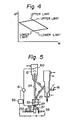
- Fig. 4 there is shown an operating range for regulating the pressure difference APT between the two reactors and the amount of sand W in the system.
- the range is shown as a lozenge which is determined after setting the respective upper and lower limits of the two fluidized bed levels by taking the structural factors such as the positions of the conduits 21 and 28 into consideration.
- the position of the lozenge in Fig. 4 will be displaced upwardly as the circulation rate of the sand decreases and vice-versa.
- the preferred set of operating conditions is naturally the center of the lozenge.
- Regulation or control of the amount of the sand in the system is determined on the basis of the respective levels of the fluidized pyrolysis bed and combustion bed. These levels are conventionally determined by measuring the pressure difference between the upper portion and the lower portion of each of the fluidized beds. On the basis of the above determination the amount of sand in the system is appropriately adjusted by actuation of the discharging means 35, 36 and 37 and/or the sand feeder 50 disposed between the sand hopper 40 and the combustion reactor 12 (Fig. 3).
- a lifting nozzle 51 is disposed for injecting gas upwardly to lift the sand from the reservoir 22 to the free board of the regenerator 12 through the lifting conduit 24.
- the feed rate of the gas may be controlled by a device such as a valve 52.
- the gas injected upwardly from the nozzle 51 may be air or a mixture of air and vapor.
- the lower end of the lifting conduit 24 is funnel shaped as illustrated in Fig.
- a fluidizing ring 55 is mounted around the nozzle 51, and below the opening 54 and air which is fed through a flow-meter 57 and a flow regulating valve 58 is blown in a downward or diagonally downward direction from an annular gap 56.
- the air injected or blown out of the ring 55 causes disturbance in the fluidizing medium or sand adjacent the nozzle 51 thereby decreasing the angle of repose for the sand and thereby it becomes easy to make the sand flow toward the upper zone of the nozzle 51 where the sand is sucked into the funnel end 53 due to ejection of the lifting gas from the nozzle opening 54.
- the feed rate of the air to the fluidizing ring 55 has an important effect on the circulation rate of the sand since any variation in the feed rate of the air to the ring 55 causes a change in the fluidization around the nozzle 51 thereby causing variation in the amount of sand blown into the lifting conduit 24 through its funnel end 53.
- the relationship of the feed rate of the air to the ring 55 and the circulation rate of the sand is shown in Fig. 8.
- the dotted line “I" is a border between the stable zone (S) and the unstable zone (U).
- three curves C i , C 2 and C 3 are illustrated each of which represents the relationship under a certain feed rate of lifting air, respectively wherein C,>C 2 >C 3 .
- the circulation rate increases as the ring air is increased provided that it is within a certain range. Accordingly, by utilizing the relationship shown in Fig. 8, it is made possible not only to stabilize the lifting rate of the sand but also to regulate the same.
- the pressure loss in the conveying duct for the powdery material varies depending on the mixing ratio in the mixture of the conveying gas and the material to be delivered thereby.
- the concentration of the sand in the upwardly moving mixture is relatively thin and, thus, it is possible to measure the circulation rate of the mixture by sensing the pressure difference between the two points in the Ifiting conduit 24.
- the mixture may cause plugging or clogging of the pressure sensing ports and, thus, the sensing in the lifting conduit may not be appropriate. Therefore, it is rather preferred to provide one sensing port 59 in the nozzle 51 and the other sensing port 60 at the top portion of the feed board in the regenerator 12 where the possibility of plugging by the sand may be negligible.
- the circulation rate of the sand may be measured. Since with this arrangement there is little chance of plugging the ports by sand, it is possible to detect the pressure difference under the stable condition.
- the pressure difference AP is measured by a detector 61 which delivers the signal corresponding to AP to a controller 56 and this controller 56 regulates the valve 58 so as to regulate the ring air thereby controlling the circulation rate of the sand as explained with respect to Fig. 8.
- the increase of the circulation rate of the sand only by the regulation of the ring air.
- the ring air is regulated so as to make the circulation rate of the sand to be beyond its upper limit, air or mixture of air and vapor may blow upwardly into the pyrolysis reactor 11 through the conduit 21. Therefore, if it is desired to increase the circulation rate of the sand under critical conditions, the feed rate of the lifting air is to be increased-for example, from the C, side to the C 3 side in Fig. 8 by regulating the valve 52.
- the superficial velocity is naturally determined to maintain the desired fluidized state by regulating the blower orvalve.
- a part of the pyrolysis gas generated is utilized as a fluidizing gas for the pyrolysis reactor 11 by means of the blower 43.
- the flow rate of the gas is measured by a flow meter 61 and, depending on the information from the flow meter, a controller 62 regulates a regulator valve 63 or the blower 43 so as to maintain the desired flow rate.
- a temperature detector 64 is arranged to sense the temperature of the fluidized bed 17 and forward its information to the controller 62 which incorporates the sensed temperature value for determining and controlling the feed rate of the fluidizing gas.
- pressure difference between the two reactors means the difference in pressure between the free boards of the two reactors.
- pressures at points 65 and 66 in the free boards of the pyrolysis reactor 11 and combustion reactor 12, respectively are sensed by pressure gauges 67 and 68 which deliver the information regarding respective pressure values to a pressure controller 69 for determining the pressure difference APT-
- the controller 69 regulates either or both of valves 70 and 71 disposed in output lines of pyrolysis gas and exhaust gas, respectively so as to maintain the desired pressure difference.
- Control system for maintaining the pressure difference has been explained above in a simplified form, but it is to be understood that other system may also be utilized.
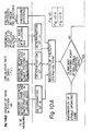
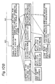
- Fig. 10 is a flow chart of such a comprehensive control system.
- Fig. 10 is divided into Figs. 10A and 10B which are to be reviewed in combination.
- the amount of sand in the system is determined by the pressure difference between the upper portion and the lower portion in each of the fluidized beds
- the circulation rate of the sand is determined by the pressure difference between the upper and lower parts in the regenerator
- the superficial velocity in the pyrolysis reactor is obtained from the flow meter for pyrolysis reactor fluidizing gas. Taking these values together with the pressure difference AP, between the two reactors, the preferable operating point, ideal operating point and the safety operating zone around that point are determined.
- Optimum operation is, thus, carried out by firstly judging whether the operation is within the safety zone and then, based on this judgement, respective signals are supplied to each of the controllers as to whether the operating condition of the respective portion is to be maintained or changed to achieve and maintain the continuous and stable operation of the system.
- the optimum operating point would be selected as the center of the safety operation zone referred to above.
- the superficial velocity in the pyrolysis reactor may be eliminated from the factors for controlling the system.
- the limits of the safety operation zone are determined taking the following into consideration.
- the gas sealing of both conduits 21 and 28 is effected by using the thermal fluidizing medium, i.e. the sand. Therefore, there must be enough sand in the coupling conduits while the sand is continuously circulating between the two reactors. Such satisfactory material sealing may be accomplished if each of the fluidized bed levels is maintained within a certain range.
- the levels H RA and H RG are functions of W, F S , V,, and AP,.
- the respective limits of the levels of H RA and H are defined as follows.
- the respective values of W, F s , V f and ⁇ P t are selected as exemplified below for determining the levels H RA and H RG ⁇
- the specific values noted below are merely examples and are not ones limiting the present invention.
- W is to be determined referring to the size and structure of the reactors. However, in general, it may be the amount of sand which gives the following levels during the normal operation.
- reinstatement of the levels to the desired levels may be achieved by actuation of the valve 70 (Fig. 9) and/or changing the circulation rate of the sand.
- the circulation rate is primarily altered by regulating the ring air as explained referring to Fig. 8, since the operation mode in the regenerator is relatively stable compared to that in the pyrolysis reactor where the char and tar are spattering.
- F s is determined by the energy balance taking into consideration the feed rate and water content of material to be pyrolyzed and the temperature conditions in the two reactors. The difference in temperature between the two reactors is usually set within the range of 20°C through 300°C. In the present system, F s is related to the feed rate of the lifting air in the combustion reactor in a substantially linear relationship and may be determined independently of the feed rate of the fluidizing gas for the pyrolysis reactor.
- V f it is independent from the feed rate of the lifting air.
- the lower limit of V I is determined so as to be the minimum value which may be able to fluidize the pyrolysis fluidized bed and the upper limit thereof is one which may not cause remarkable abrasion of the fluidizing medium of the sand and excessive scattering of the same.
- the value thereof may be in the following range:
- V is set to be 0.4 m/s through 1.2 m/s and, when the pyrolysis gas is generated, it is increased thereby.
- the operating point if usually selected so that V f becomes 0.8 m/s through 2.5 m/s.
- the preferred operational zone By determining the amount of W under operation and the value of F s based on the feed rate of material to be processed or pyrolyzed, the preferred operational zone will assume, according to the formulas above, a lozenge shape as illustrated in Fig. 11. Continuous and stable operation is obtained by regulating ⁇ P t and/or V, so that the operating point is within the lozenge in Fig. 11. During the usual operation, the actual value of ⁇ P t is, for example, between -49 kPa (-5000 mm Aq) and 49 kPa (5000 mm Aq).
- calorific or thermal energy Q A to be supplied to the pyrolysis reactor may be expressed by the following equation: wherein
- T RA T RA
- T RA is expressed as follows:
- the following factors may be controlled.
- T RA it is preferable to regulate the T RA by controlling the feed rate of the auxiliary gas but it is preferably controlled to maintain T RG below the temperature of producing clinkers in the regenerator. If such regulation alone is not satisfactory, circulation rate of the sand will next be adjusted by regulating the ring air. If it is still necessary to adjust the T RG even with the controls above, (i.e. controls of the items "b" and "c"), the feed rate of the material will be regulated. In this last instance, if the F, and T RG are maintained constant, it is necessary to keep constant as viewed from the equation (5). If T RA is maintained constant, it may be enough to keep Q o Z substantially constant since Q S and Q 6 are generally kept constant. In other words, the feed rate of material is preferably regulated so as to cancel the variation of Q o .
- the method and apparatus of the present invention have been explained referring to the treatment of municipal waste in a two-bed pyrolyzing system but they may be utilized for any other material to be pyrolyzed. Also, the continuous and stable operation has been discussed.
- non-combustible constituents such as metal, glass, earth sand and pebbles, etc. mixed therein must be separated and discharged out of the system as explained regarding the discharge means 31, 35, 36, 37, 38 and 39 etc. in Fig. 3 for maintaining continuous and stable operation. Otherwise these non-combustible constituents might fuse or stick together and become a large mass. These non-combustible constituents will be referred to as "foreign substance" for convenience.
- the foreign substance is appropriately discharged out of the system periodically and/or automatically by the control of the system as schematically illustrated in Fig. 10.
- the non-combustible constituents or foreign substance may cause trouble in the operation.
- the foreign substance is conveyed from the reactor 11, without being discharged outwardly through the discharging means 35 to the ejecting reservoir 22 through the conduit 21, they might stay or dwell around the annular gap 56 of the ring 55 (Figs. 6 and 7), and disturb the air flow through the gap 56 thereby abruptly increasing the circulation rate of the sand and making the operation unstable.
- the present invention further provides the improvement for overcoming such drawback for necessitating temporary shutdown of the system.
- the sealing state between the two reactors 11 and 12 is monitored by pressure difference sensors 80 and 81 adapted to sense the pressure difference between the opposite ends of the coupling conduits 21 and 28, respectively.
- a pressure difference between the free board of the regenerator 12 and the ejecting reservoir is monitored by a gauge 82 so as to detect the condition in advance of the occurrence of unstable operation or blocking.
- the flow meter 61 (Fig. 5) may be utilized in lieu of the gauge 82.
Landscapes
- Chemical & Material Sciences (AREA)
- Engineering & Computer Science (AREA)
- Oil, Petroleum & Natural Gas (AREA)
- Materials Engineering (AREA)
- Organic Chemistry (AREA)
- Dispersion Chemistry (AREA)
- Combustion & Propulsion (AREA)
- Gasification And Melting Of Waste (AREA)
Claims (13)
Zirkulieren des Sandes durch den Pyrolysereaktor (11) und den Verbrennungsreaktor (12), wobei die Reaktoren miteinander durch geneigte Leitungsmittel (21, 28) gekuppelt sind, und wobei der Sand vom oberen Teil eines der Reaktoren zum unteren Teil des anderen Reaktors durch die Leitungsmittel zirkuliert wird, und wobei der Sand innerhalb des Verbrennungsreaktors vom unteren Teil zum oberen Teil durch eine Hubleitung (24) angehoben wird, die sich zwischen dem unteren Teil und dem oberen Teil des Verbrennungsreaktors erstreckt, und zwar durch Eingeben unter Druck stehender Luft oder eine Mischung von Luft und Dampf aus einer Düse (51) in das untere Ende (53) der Hubleitung, wobei das Verfahren gekennzeichnet ist dadurch, daß die Zirkulationsgewischwindigkeit des Sandes dadurch gesteuert wird, daß man einen Luftstrom reguliert, der in einer nach unten oder diagonal nach unten weisenden Richtung durch Ringspaltmittel (55, 56) eingegeben wird, die koaxial die Düse (51) umgeben.
Applications Claiming Priority (4)
| Application Number | Priority Date | Filing Date | Title |
|---|---|---|---|
| JP139271/79 | 1979-10-30 | ||
| JP139272/79 | 1979-10-30 | ||
| JP13927279A JPS5944348B2 (ja) | 1979-10-30 | 1979-10-30 | 多塔循環式熱分解装置の流動媒体揚送装置 |
| JP13927179A JPH0233754B2 (ja) | 1979-10-30 | 1979-10-30 | Netsubunkaihoho |
Publications (2)
| Publication Number | Publication Date |
|---|---|
| EP0028021A1 EP0028021A1 (de) | 1981-05-06 |
| EP0028021B1 true EP0028021B1 (de) | 1986-09-24 |
Family
ID=26472126
Family Applications (1)
| Application Number | Title | Priority Date | Filing Date |
|---|---|---|---|
| EP80106537A Expired EP0028021B1 (de) | 1979-10-30 | 1980-10-24 | Verfahren und Apparat zur Pyrolyse |
Country Status (3)
| Country | Link |
|---|---|
| US (2) | US4344373A (de) |
| EP (1) | EP0028021B1 (de) |
| DE (1) | DE3071778D1 (de) |
Families Citing this family (25)
| Publication number | Priority date | Publication date | Assignee | Title |
|---|---|---|---|---|
| US4432290A (en) * | 1979-10-30 | 1984-02-21 | The Agency Of Industrial Science And Technology | Method of pyrolyzing organic material using a two-bed pyrolysis system |
| US4449461A (en) * | 1981-11-10 | 1984-05-22 | Jacob Gorbulsky | Process and apparatus for hydrocarbons recovery from solid fuels |
| DE3310534A1 (de) * | 1983-03-23 | 1984-10-04 | C. Deilmann AG, 4444 Bad Bentheim | Einrichtung zur gewinnung von energie aus pyrolisierbaren, kohlenstoffhaltigen abfallstoffen wechselnder zusammensetzung |
| GB2150854B (en) * | 1983-12-06 | 1987-09-16 | Coal Ind | Hot gas generation |
| DE3447147A1 (de) * | 1984-12-22 | 1986-06-26 | Christian Dr.-Ing. 8570 Pegnitz Koch | Verfahren und vorrichtung fuer die stickoxidfreie dampferzeugung mit fossilen brennstoffen |
| US4676177A (en) * | 1985-10-09 | 1987-06-30 | A. Ahlstrom Corporation | Method of generating energy from low-grade alkaline fuels |
| US4823712A (en) * | 1985-12-18 | 1989-04-25 | Wormser Engineering, Inc. | Multifuel bubbling bed fluidized bed combustor system |
| US4865625A (en) * | 1988-05-02 | 1989-09-12 | Battelle Memorial Institute | Method of producing pyrolysis gases from carbon-containing materials |
| US4930429A (en) * | 1988-08-11 | 1990-06-05 | Ahlstromforetagen Svenska Ab | Apparatus and process for generating steam from wet fuel |
| US5034498A (en) * | 1989-07-19 | 1991-07-23 | Biocarbons Corporation | Method and apparatus for producing water-soluble resin and resin product made by that method |
| US5115084A (en) * | 1989-07-19 | 1992-05-19 | Biocarbons Corporation | Method for controlling oil reservoir permeability using biomass oil |
| FI931785A7 (fi) * | 1993-04-20 | 1994-10-21 | Valtion Teknillinen | Menetelmä ja laitteisto nestemäisen polttoaineen valmistamiseksi pyrolysoimalla raakapolttoainetta |
| CN1234106A (zh) * | 1996-10-22 | 1999-11-03 | 特雷德克公司 | 用热解法处理废物并利用废物能量的设备 |
| DE19950062A1 (de) * | 1999-10-16 | 2001-04-26 | Siempelkamp Guss Und Anlagente | Verfahren und Anlage zur Aufbereitung von flüssigen und/oder festen organischen Abfallstoffen |
| RU2174948C1 (ru) * | 2000-11-23 | 2001-10-20 | Российское акционерное общество энергетики и электрификации "Единая энергетическая система России" | Способ термической переработки углеродосодержащего сырья с получением углеродных сорбентов и установка для его осуществления |
| FR2851570B1 (fr) * | 2003-02-24 | 2007-07-27 | Inst Francais Du Petrole | Installation et procede de gazeification multi-etapes d'une charge comprenant de la matiere organique |
| FI120556B (fi) * | 2006-12-11 | 2009-11-30 | Foster Wheeler Energia Oy | Menetelmä ja laite lämpöä sitovan leijupetireaktorin lämpötilan säätämiseksi |
| FI122778B (fi) * | 2008-03-31 | 2012-06-29 | Metso Power Oy | Pyrolyysimenetelmä kattilan yhteydessä ja pyrolyysilaitteisto |
| US9441887B2 (en) * | 2011-02-22 | 2016-09-13 | Ensyn Renewables, Inc. | Heat removal and recovery in biomass pyrolysis |
| CN108237024A (zh) * | 2017-12-28 | 2018-07-03 | 陕西延长石油(集团)有限责任公司 | 一种两级旋风分离器 |
| FR3087353B1 (fr) * | 2018-10-18 | 2022-12-16 | Arkema France | Procede de traitement d'un effluent gazeux issu d'une decomposition pyrolytique d'un polymere |
| ES3058360T3 (es) | 2020-04-22 | 2026-03-10 | Sumitomo SHI FW Energia Oy | Sistema de reactor de lecho fluidizado y procedimiento de funcionamiento de un sistema de reactor de lecho fluidizado |
| TW202432241A (zh) | 2022-10-13 | 2024-08-16 | 荷蘭商Asm Ip私人控股有限公司 | 蒸氣遞送設備、氣相反應器及用於監測及控制蒸氣遞送系統之方法 |
| CN116769495B (zh) * | 2023-05-30 | 2025-09-19 | 湖南新九方科技有限公司 | 一种干化热解一体炉控制方法、系统、设备及存储介质 |
| WO2025019808A2 (en) * | 2023-07-20 | 2025-01-23 | Czero, Inc. | Methods and reactors for direct catalytic conversion of hydrocarbons to hydrogen |
Family Cites Families (10)
| Publication number | Priority date | Publication date | Assignee | Title |
|---|---|---|---|---|
| USRE26514E (en) | 1968-12-31 | Treatment and disposal of waste sludges | ||
| DE908372C (de) * | 1942-10-23 | 1954-04-05 | Universal Oil Prod Co | Verfahren und Vorrichtung zur Aufrechterhaltung eines im wasentlichen gleichfoermigen Stromes einer Fluessigkeit oder fein verteilter fester Stoffe |
| US2601676A (en) * | 1950-03-10 | 1952-06-24 | Shell Dev | Control of flow of fluidized solids |
| US2972503A (en) * | 1960-02-16 | 1961-02-21 | Socony Mobil Oil Co Inc | Method for control of operation of pneumatic lift and apparatus therefor |
| FR1498034A (fr) * | 1966-10-28 | 1967-10-13 | Appareil pour l'incinération continue des déchets ou gadoues | |
| US3366080A (en) * | 1966-12-08 | 1968-01-30 | Dorr Oliver Inc | Fluidized bed combustion system |
| US3853498A (en) * | 1972-06-28 | 1974-12-10 | R Bailie | Production of high energy fuel gas from municipal wastes |
| GB1484130A (en) * | 1974-10-25 | 1977-08-24 | Kunii D | Pyrolytic process and apparatus for solid waste disposal |
| US4206186A (en) * | 1975-02-06 | 1980-06-03 | Holter Gesellschaft Fur Patentverwertungsverfahren Mbh | Refuse pyrolysis |
| US4057402A (en) * | 1976-06-28 | 1977-11-08 | Institute Of Gas Technology | Coal pretreatment and gasification process |
-
1980
- 1980-10-22 US US06/199,543 patent/US4344373A/en not_active Expired - Lifetime
- 1980-10-24 DE DE8080106537T patent/DE3071778D1/de not_active Expired
- 1980-10-24 EP EP80106537A patent/EP0028021B1/de not_active Expired
-
1982
- 1982-05-26 US US06/382,350 patent/US4437416A/en not_active Expired - Lifetime
Also Published As
| Publication number | Publication date |
|---|---|
| US4344373A (en) | 1982-08-17 |
| DE3071778D1 (en) | 1986-11-06 |
| EP0028021A1 (de) | 1981-05-06 |
| US4437416A (en) | 1984-03-20 |
Similar Documents
| Publication | Publication Date | Title |
|---|---|---|
| EP0028021B1 (de) | Verfahren und Apparat zur Pyrolyse | |
| CN101495808B (zh) | 带有横向传送系统的水平取向气化器 | |
| CA1158421A (en) | Fluidized bed reactor | |
| US6418866B1 (en) | Operating method of fluidized-bed incinerator and the incinerator | |
| EP0766041B1 (de) | Thermischer wirbelschichtreaktor | |
| EP2693118A1 (de) | Wirbelschichtofen | |
| US4757771A (en) | Method and apparatus for stable combustion in a fluidized bed incinerator | |
| JPH0133722B2 (de) | ||
| EP0050519B1 (de) | Wirbelbettverbrennungsvorrichtung | |
| US4823739A (en) | Apparatus for control of the heat transfer produced in a fluidized bed | |
| KR101734613B1 (ko) | 유동상로 및 폐기물의 처리 방법 | |
| EP2940386B1 (de) | Schmelzofen für abfälle | |
| GB2149151A (en) | Fluidized bed fuel burning | |
| US4767315A (en) | Method of controlling the depth of a fluidized bed in a power plant and a power plant with means for controlling the bed depth | |
| EP0369004B1 (de) | Wirbelbettofen mit innerer umwälzung und verfahren zur steuerung desselben | |
| EP0687855B1 (de) | Zirkulierender Wirbelschichtreaktor für minderwertige Brennstoffe | |
| US4813381A (en) | Controlling thermal transmission rate at a fast fluidized bed reactor | |
| JP6299467B2 (ja) | 廃棄物ガス化溶融装置及び廃棄物ガス化溶融方法 | |
| US4324620A (en) | Pyrolyzing apparatus | |
| EP0028458A2 (de) | Dampferzeuger mit Wirbelschicht-Brennkammer | |
| JPS5855408B2 (ja) | 都市ごみなどの熱分解装置 | |
| JPH0233754B2 (ja) | Netsubunkaihoho | |
| US4750434A (en) | Mill/dryer gas temperature control | |
| GB2132500A (en) | Classification and recycling of fluidised bed material | |
| US20150315500A1 (en) | Method of and apparatus for controlling a gasifier |
Legal Events
| Date | Code | Title | Description |
|---|---|---|---|
| PUAI | Public reference made under article 153(3) epc to a published international application that has entered the european phase |
Free format text: ORIGINAL CODE: 0009012 |
|
| 17P | Request for examination filed |
Effective date: 19810105 |
|
| AK | Designated contracting states |
Designated state(s): DE FR GB NL |
|
| GRAA | (expected) grant |
Free format text: ORIGINAL CODE: 0009210 |
|
| AK | Designated contracting states |
Kind code of ref document: B1 Designated state(s): DE FR GB NL |
|
| REF | Corresponds to: |
Ref document number: 3071778 Country of ref document: DE Date of ref document: 19861106 |
|
| ET | Fr: translation filed | ||
| PLBE | No opposition filed within time limit |
Free format text: ORIGINAL CODE: 0009261 |
|
| STAA | Information on the status of an ep patent application or granted ep patent |
Free format text: STATUS: NO OPPOSITION FILED WITHIN TIME LIMIT |
|
| 26N | No opposition filed | ||
| PGFP | Annual fee paid to national office [announced via postgrant information from national office to epo] |
Ref country code: NL Payment date: 19871031 Year of fee payment: 8 |
|
| PG25 | Lapsed in a contracting state [announced via postgrant information from national office to epo] |
Ref country code: GB Effective date: 19891024 |
|
| PG25 | Lapsed in a contracting state [announced via postgrant information from national office to epo] |
Ref country code: NL Effective date: 19900501 |
|
| NLV4 | Nl: lapsed or anulled due to non-payment of the annual fee | ||
| GBPC | Gb: european patent ceased through non-payment of renewal fee | ||
| PG25 | Lapsed in a contracting state [announced via postgrant information from national office to epo] |
Ref country code: FR Effective date: 19900629 |
|
| PG25 | Lapsed in a contracting state [announced via postgrant information from national office to epo] |
Ref country code: DE Effective date: 19900801 |
|
| REG | Reference to a national code |
Ref country code: FR Ref legal event code: ST |