EP0028037A1 - Procédé et installation pour sécher et préchauffer du charbon à coke dans un tube de transport pneumatique unique - Google Patents
Procédé et installation pour sécher et préchauffer du charbon à coke dans un tube de transport pneumatique unique Download PDFInfo
- Publication number
- EP0028037A1 EP0028037A1 EP80200900A EP80200900A EP0028037A1 EP 0028037 A1 EP0028037 A1 EP 0028037A1 EP 80200900 A EP80200900 A EP 80200900A EP 80200900 A EP80200900 A EP 80200900A EP 0028037 A1 EP0028037 A1 EP 0028037A1
- Authority
- EP
- European Patent Office
- Prior art keywords
- flow tube
- entrained flow
- gas
- entrained
- partial
- Prior art date
- Legal status (The legal status is an assumption and is not a legal conclusion. Google has not performed a legal analysis and makes no representation as to the accuracy of the status listed.)
- Granted
Links
Images
Classifications
-
- F—MECHANICAL ENGINEERING; LIGHTING; HEATING; WEAPONS; BLASTING
- F26—DRYING
- F26B—DRYING SOLID MATERIALS OR OBJECTS BY REMOVING LIQUID THEREFROM
- F26B3/00—Drying solid materials or objects by processes involving the application of heat
- F26B3/02—Drying solid materials or objects by processes involving the application of heat by convection, i.e. heat being conveyed from a heat source to the materials or objects to be dried by a gas or vapour, e.g. air
- F26B3/10—Drying solid materials or objects by processes involving the application of heat by convection, i.e. heat being conveyed from a heat source to the materials or objects to be dried by a gas or vapour, e.g. air the gas or vapour carrying the materials or objects to be dried with it
-
- C—CHEMISTRY; METALLURGY
- C10—PETROLEUM, GAS OR COKE INDUSTRIES; TECHNICAL GASES CONTAINING CARBON MONOXIDE; FUELS; LUBRICANTS; PEAT
- C10B—DESTRUCTIVE DISTILLATION OF CARBONACEOUS MATERIALS FOR PRODUCTION OF GAS, COKE, TAR, OR SIMILAR MATERIALS
- C10B57/00—Other carbonising or coking processes; Features of destructive distillation processes in general
- C10B57/08—Non-mechanical pretreatment of the charge, e.g. desulfurization
- C10B57/10—Drying
-
- F—MECHANICAL ENGINEERING; LIGHTING; HEATING; WEAPONS; BLASTING
- F26—DRYING
- F26B—DRYING SOLID MATERIALS OR OBJECTS BY REMOVING LIQUID THEREFROM
- F26B17/00—Machines or apparatus for drying materials in loose, plastic, or fluidised form, e.g. granules, staple fibres, with progressive movement
- F26B17/10—Machines or apparatus for drying materials in loose, plastic, or fluidised form, e.g. granules, staple fibres, with progressive movement with movement performed by fluid currents, e.g. issuing from a nozzle, e.g. pneumatic, flash, vortex or entrainment dryers
- F26B17/101—Machines or apparatus for drying materials in loose, plastic, or fluidised form, e.g. granules, staple fibres, with progressive movement with movement performed by fluid currents, e.g. issuing from a nozzle, e.g. pneumatic, flash, vortex or entrainment dryers the drying enclosure having the shape of one or a plurality of shafts or ducts, e.g. with substantially straight and vertical axis
Definitions
- the invention relates to a method according to the preamble of claim 1 and an apparatus for performing the method according to the invention.
- Coking coal is currently dried and preheated in single-stage or multi-stage, but usually two-stage entrained flow apparatus.
- An entrained flow apparatus consists of a generally vertical entrained flow tube and one or more downstream cyclones in which the gas / solid separation is carried out.
- the heat transfer gas is usually generated in a combustion chamber and mixed with recirculated vapors.
- a method for drying and preheating coking coal in a single entrained flow tube has now been proposed, in which, in a manner known per se, a hot gas stream, which entrains the ground, moist coal which is fed in at the lower end of the entrained flow tubes, rises and out of the top At the end of the entrained flow tube, all of the dried and preheated coal is separated from the gas stream and the coarser grain fractions of the feed material are separated at least at one point in the entrained flow tube and immediately subsequently fed back into the entrained flow tube containing only the finer grain fractions 28 41 088.0).
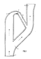
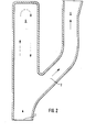
- the entrained flow tube has a curved course in the area in which the coarser grain fractions are to be separated, and leads into the further entrained flow path in a region not set on the curvature side Main branch for gas and the finer grain fractions and a branch branch following the curved course for the coarser grain fractions and at the end of the branch branch a device for re-feeding the coarser grain fractions into the further entrained flow path is arranged.
- this method can be carried out in two alternative ways.
- the first way is that the smaller gas flow, which stirs the coarser grain fractions with it, is led in a kind of bypass to the main flow path of the entrained flow pipe.
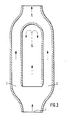
- the second way is that the coarse grain fractions carrying the sub-stream form vortices in a direction-constant, dead-running pipe end, in which the upward movement of the coal bodies is slowed down. Because of their gravity, these grains then fall down again and become swept away by the general gas flow and thus accelerated again.
- the method according to the invention has proven to be particularly effective if the coarser grain fractions previously separated sinks almost vertically downwards before being reunited into the main stream, since the subsequent acceleration is then particularly intensive.
- the vortex formation of the smaller partial flow and thus of the coarser grain fractions according to the second alternative is particularly favorable if the corresponding pipe section which is initially dead constant in direction is expanded in cross-section with respect to the entrainment flow pipe.
- the gas / solid mixture flows at high speed through entrained flow tube 1 and undergoes a sudden change in direction through branch 2.
- the different inertia of coarser and finer grain fractions causes that the finer grain fractions follow the change in direction of the main gas flow, while the coarser grain fractions maintain their old direction of movement.
- the latter are then deflected from their original path by a curved pipe section 4 and passed into the re-introduction channel 5. Due to the gravity of the particles, their friction on the elbow 4 and the throttling of the gas flow, their speed is considerably reduced and at the same time the direction of movement is changed so that they experience a new acceleration when they are fed back into the further course of the entrained flow tube 6.
- the desired high relative speed with respect to the gas flow is present, which leads to an increase in the heat transfer.
- the cross section of the bypass can be changed by means of throttle valves 7.
- this throttle valve is attached to the inside of the pipe bend, on the one hand it does not hinder the coal flow which flies along the outer wall of the bend due to the centrifugal acceleration, but on the other hand it offers the carrier gas a sufficiently high resistance and thus the extent of the grain fractions determined, which is separated by the bypass.
- the stronger the thrush. is, the less fine grain fractions get into the bypass.
- With such a flap the partial carrier gas flow which takes the path through the bypass can be reduced to a minimum; mechanical loads on the granular material are largely avoided.
- the gas / solid mixture flowing at high speed in the entrained flow tube is also suddenly deflected, the gas being able to entrain only the finer grain fractions due to the sudden change in direction. It immediately re-enters the downstream flow pipe.
- the coarser grain fractions which cannot change their direction of movement so quickly due to their inertia, are thrown into a dead tube piece 8 and set there in whirling motion and braked completely or with a possibly remaining speed, the particles collide with the end of the dead tube piece and are distracted from their direction of flight. In free fall, they now fall back from the dead space in the direction opposite to the gas flow and are entrained at the branch point by the gas flow rising from below and fed to the further course of the entrained flow pipe.
Landscapes
- Engineering & Computer Science (AREA)
- Chemical & Material Sciences (AREA)
- Mechanical Engineering (AREA)
- General Engineering & Computer Science (AREA)
- Materials Engineering (AREA)
- Microbiology (AREA)
- Life Sciences & Earth Sciences (AREA)
- Oil, Petroleum & Natural Gas (AREA)
- Organic Chemistry (AREA)
- Solid Fuels And Fuel-Associated Substances (AREA)
- Coke Industry (AREA)
- Drying Of Solid Materials (AREA)
- Production Of Liquid Hydrocarbon Mixture For Refining Petroleum (AREA)
Applications Claiming Priority (2)
| Application Number | Priority Date | Filing Date | Title |
|---|---|---|---|
| DE2942878 | 1979-10-24 | ||
| DE2942878A DE2942878C2 (de) | 1979-10-24 | 1979-10-24 | Verfahren und Vorrichtung zur Trocknung und Vorerhitzung von Kokskohle in einem einzigen Flugstromrohr |
Publications (2)
| Publication Number | Publication Date |
|---|---|
| EP0028037A1 true EP0028037A1 (fr) | 1981-05-06 |
| EP0028037B1 EP0028037B1 (fr) | 1982-05-19 |
Family
ID=6084207
Family Applications (1)
| Application Number | Title | Priority Date | Filing Date |
|---|---|---|---|
| EP80200900A Expired EP0028037B1 (fr) | 1979-10-24 | 1980-09-25 | Procédé et installation pour sécher et préchauffer du charbon à coke dans un tube de transport pneumatique unique |
Country Status (9)
| Country | Link |
|---|---|
| US (1) | US4380125A (fr) |
| EP (1) | EP0028037B1 (fr) |
| JP (1) | JPS5674186A (fr) |
| AU (1) | AU533365B2 (fr) |
| BR (1) | BR8006815A (fr) |
| CA (1) | CA1144748A (fr) |
| DE (2) | DE2942878C2 (fr) |
| ES (1) | ES8106926A1 (fr) |
| ZA (1) | ZA806325B (fr) |
Families Citing this family (2)
| Publication number | Priority date | Publication date | Assignee | Title |
|---|---|---|---|---|
| JPS6250393A (ja) * | 1985-08-28 | 1987-03-05 | Mitsubishi Heavy Ind Ltd | 石炭の熱処理法 |
| DE50111696D1 (de) * | 2001-10-02 | 2007-02-01 | Schoppe Fritz | Verfahren und Vorrichtung zur gleichmässigen Erhitzung eines Staubkörnergemisches in einer Strömung heisser Gase |
Citations (3)
| Publication number | Priority date | Publication date | Assignee | Title |
|---|---|---|---|---|
| GB418462A (en) * | 1933-05-11 | 1934-10-25 | British Rema Mfg Company Ltd | Improvements relating to drying apparatus |
| FR777901A (fr) * | 1933-09-07 | 1935-03-05 | Esch Werke K G Maschinenfabrik | Séchoir pneumatique |
| DE1180324B (de) * | 1961-02-04 | 1964-10-22 | Buettner Werke Ag | Steigrohr eines Einkanalstromtrockners im Bereich der Gutaufgabe |
Family Cites Families (5)
| Publication number | Priority date | Publication date | Assignee | Title |
|---|---|---|---|---|
| US3049343A (en) * | 1959-08-25 | 1962-08-14 | Polysius G M B H Fa | Apparatus for heating cement powder or similar fine-granular materials |
| DE2558506C2 (de) * | 1975-12-24 | 1982-03-11 | Klöckner-Humboldt-Deutz AG, 5000 Köln | Verfahren zur thermischen Behandlung von staubförmigem Gut, insbesondere zum Brennen von Zement in mehreren Stufen |
| DE2815461C2 (de) * | 1978-04-10 | 1987-01-29 | Klöckner-Humboldt-Deutz AG, 5000 Köln | Verfahren und Vorrichtung zur thermischen Behandlung von feinkörnigem Gut mit heißen Gasen |
| JPS5522322A (en) * | 1978-08-04 | 1980-02-18 | Sumitomo Cement Co Ltd | Method of heating powder material and device therefor |
| US4270900A (en) * | 1980-01-07 | 1981-06-02 | Allis-Chalmers Corporation | Suspension preheater |
-
1979
- 1979-10-24 DE DE2942878A patent/DE2942878C2/de not_active Expired
-
1980
- 1980-09-25 DE DE8080200900T patent/DE3060451D1/de not_active Expired
- 1980-09-25 EP EP80200900A patent/EP0028037B1/fr not_active Expired
- 1980-10-10 AU AU63168/80A patent/AU533365B2/en not_active Ceased
- 1980-10-15 ZA ZA00806325A patent/ZA806325B/xx unknown
- 1980-10-20 CA CA000362819A patent/CA1144748A/fr not_active Expired
- 1980-10-21 ES ES496114A patent/ES8106926A1/es not_active Expired
- 1980-10-23 US US06/199,953 patent/US4380125A/en not_active Expired - Lifetime
- 1980-10-23 BR BR8006815A patent/BR8006815A/pt unknown
- 1980-10-24 JP JP15003680A patent/JPS5674186A/ja active Granted
Patent Citations (3)
| Publication number | Priority date | Publication date | Assignee | Title |
|---|---|---|---|---|
| GB418462A (en) * | 1933-05-11 | 1934-10-25 | British Rema Mfg Company Ltd | Improvements relating to drying apparatus |
| FR777901A (fr) * | 1933-09-07 | 1935-03-05 | Esch Werke K G Maschinenfabrik | Séchoir pneumatique |
| DE1180324B (de) * | 1961-02-04 | 1964-10-22 | Buettner Werke Ag | Steigrohr eines Einkanalstromtrockners im Bereich der Gutaufgabe |
Also Published As
| Publication number | Publication date |
|---|---|
| US4380125A (en) | 1983-04-19 |
| CA1144748A (fr) | 1983-04-19 |
| AU533365B2 (en) | 1983-11-17 |
| ES496114A0 (es) | 1981-09-16 |
| JPS5674186A (en) | 1981-06-19 |
| DE3060451D1 (en) | 1982-07-08 |
| ES8106926A1 (es) | 1981-09-16 |
| DE2942878C2 (de) | 1983-10-06 |
| BR8006815A (pt) | 1981-04-28 |
| AU6316880A (en) | 1981-04-30 |
| JPH0120200B2 (fr) | 1989-04-14 |
| ZA806325B (en) | 1981-10-28 |
| EP0028037B1 (fr) | 1982-05-19 |
| DE2942878A1 (de) | 1981-05-07 |
Similar Documents
| Publication | Publication Date | Title |
|---|---|---|
| DE2548948C2 (de) | Zyklonabscheider | |
| EP0178316B1 (fr) | Separateur cyclone | |
| DE3521638A1 (de) | Verfahren und turbo-sichter zum streuwindsichten, insbesondere von zement | |
| DE2161411B2 (de) | Verfahren und vorrichtung zum reduzieren des alkaligehalts von zementklinker | |
| DE2838173A1 (de) | Zyklonabscheider zum abscheiden von schwer- und staubteilen aus fasermaterial | |
| DE69717829T2 (de) | Zyklonabscheider | |
| DE69416406T2 (de) | Verfahren und vorrichtung zum abtrennen von schweren partikeln aus partikelförmigem material | |
| EP0028037B1 (fr) | Procédé et installation pour sécher et préchauffer du charbon à coke dans un tube de transport pneumatique unique | |
| EP0491278B1 (fr) | Procédé et dispositif pour le dépoussiérage et/ou le tri de matières granuleuses ou fibreuses dans un courant d'air | |
| DE3040603C2 (de) | Zentrifugalabscheider | |
| DE2401735C2 (de) | Vorrichtung zum Klassieren von in einem Trägerfluid dispergierten Feststoffteilchen | |
| DE2934590A1 (de) | Zyklonabscheider | |
| DE19718158C2 (de) | Verfahren und Vorrichtung zum windsichtenden Separieren | |
| DE2841088C2 (de) | Verfahren und Vorrichtung zur Trocknung und Vorerhitzung von Kokskohle in einem einzigen Flugstromrohr | |
| DE893905C (de) | Pneumatische Anlage zum Foerdern und Sichten von koernigem Schuettgut | |
| DE19957993A1 (de) | Kegelsichter und Verfahren zum Sichten von eingeschränkt oder nicht rieselfähigem Schüttgut | |
| DE2944383A1 (de) | Verfahren und vorrichtung zur steigerung der effektivitaet bei der erwaermung feinteiliger feststoffe in flugstromrohren | |
| DE623564C (fr) | ||
| DE1250320C2 (de) | Verfahren und vorrichtung zum trennen von zigaretten oder anderen stabfoermigen gegenstaenden | |
| DE561991C (de) | Verfahren und Einrichtung zur Verfeuerung eines Kohlenstaubkorngemisches | |
| DE2239122A1 (de) | Verfahren und einrichtung zum aufbereiten eines weitgehend trockenen gemisches | |
| AT226504B (de) | Sichter | |
| DE535312C (de) | Vorrichtung zur Abscheidung der schwereren und groeberen Bestandteile aus einem Staubluftgemischstrom | |
| DE922399C (de) | Abscheider fuer pneumatisch gefoerdertes koerniges Gut | |
| DE531445C (de) | Windsichter mit zwei in verschiedenen Ebenen uebereinander angeordneten, den Gutstrom umlenkenden Leitstellen |
Legal Events
| Date | Code | Title | Description |
|---|---|---|---|
| PUAI | Public reference made under article 153(3) epc to a published international application that has entered the european phase |
Free format text: ORIGINAL CODE: 0009012 |
|
| AK | Designated contracting states |
Designated state(s): DE FR GB IT NL |
|
| 17P | Request for examination filed |
Effective date: 19810511 |
|
| ITF | It: translation for a ep patent filed | ||
| GRAA | (expected) grant |
Free format text: ORIGINAL CODE: 0009210 |
|
| AK | Designated contracting states |
Designated state(s): DE FR GB IT NL |
|
| REF | Corresponds to: |
Ref document number: 3060451 Country of ref document: DE Date of ref document: 19820708 |
|
| PGFP | Annual fee paid to national office [announced via postgrant information from national office to epo] |
Ref country code: FR Payment date: 19840816 Year of fee payment: 5 |
|
| PGFP | Annual fee paid to national office [announced via postgrant information from national office to epo] |
Ref country code: NL Payment date: 19860930 Year of fee payment: 7 |
|
| PG25 | Lapsed in a contracting state [announced via postgrant information from national office to epo] |
Ref country code: NL Effective date: 19880401 |
|
| NLV4 | Nl: lapsed or anulled due to non-payment of the annual fee | ||
| PG25 | Lapsed in a contracting state [announced via postgrant information from national office to epo] |
Ref country code: FR Free format text: LAPSE BECAUSE OF NON-PAYMENT OF DUE FEES Effective date: 19880531 |
|
| GBPC | Gb: european patent ceased through non-payment of renewal fee | ||
| REG | Reference to a national code |
Ref country code: FR Ref legal event code: ST |
|
| PG25 | Lapsed in a contracting state [announced via postgrant information from national office to epo] |
Ref country code: GB Free format text: LAPSE BECAUSE OF NON-PAYMENT OF DUE FEES Effective date: 19881118 |
|
| PGFP | Annual fee paid to national office [announced via postgrant information from national office to epo] |
Ref country code: DE Payment date: 19920819 Year of fee payment: 13 |
|
| PG25 | Lapsed in a contracting state [announced via postgrant information from national office to epo] |
Ref country code: DE Effective date: 19940601 |
|
| PLBE | No opposition filed within time limit |
Free format text: ORIGINAL CODE: 0009261 |
|
| STAA | Information on the status of an ep patent application or granted ep patent |
Free format text: STATUS: NO OPPOSITION FILED WITHIN TIME LIMIT |