EP0028081B1 - Procédé et dispositif pour détecter l'usure par friction dans des paliers métalliques - Google Patents
Procédé et dispositif pour détecter l'usure par friction dans des paliers métalliques Download PDFInfo
- Publication number
- EP0028081B1 EP0028081B1 EP80303532A EP80303532A EP0028081B1 EP 0028081 B1 EP0028081 B1 EP 0028081B1 EP 80303532 A EP80303532 A EP 80303532A EP 80303532 A EP80303532 A EP 80303532A EP 0028081 B1 EP0028081 B1 EP 0028081B1
- Authority
- EP
- European Patent Office
- Prior art keywords
- output signal
- transducer
- frictional wear
- signal
- time
- Prior art date
- Legal status (The legal status is an assumption and is not a legal conclusion. Google has not performed a legal analysis and makes no representation as to the accuracy of the status listed.)
- Expired
Links
- 238000000034 method Methods 0.000 title claims description 6
- 239000002184 metal Substances 0.000 title description 5
- 238000012544 monitoring process Methods 0.000 claims description 4
- 229910000897 Babbitt (metal) Inorganic materials 0.000 description 6
- 238000010586 diagram Methods 0.000 description 6
- 238000010926 purge Methods 0.000 description 5
- 238000001514 detection method Methods 0.000 description 4
- 239000000919 ceramic Substances 0.000 description 1
- 238000005516 engineering process Methods 0.000 description 1
- 238000002474 experimental method Methods 0.000 description 1
- 230000006870 function Effects 0.000 description 1
- 238000013021 overheating Methods 0.000 description 1
- 230000000737 periodic effect Effects 0.000 description 1
- 238000012545 processing Methods 0.000 description 1
- 230000004044 response Effects 0.000 description 1
- 238000003466 welding Methods 0.000 description 1
Images


Classifications
-
- G—PHYSICS
- G01—MEASURING; TESTING
- G01N—INVESTIGATING OR ANALYSING MATERIALS BY DETERMINING THEIR CHEMICAL OR PHYSICAL PROPERTIES
- G01N29/00—Investigating or analysing materials by the use of ultrasonic, sonic or infrasonic waves; Visualisation of the interior of objects by transmitting ultrasonic or sonic waves through the object
- G01N29/14—Investigating or analysing materials by the use of ultrasonic, sonic or infrasonic waves; Visualisation of the interior of objects by transmitting ultrasonic or sonic waves through the object using acoustic emission techniques
Definitions
- This invention relates to a method and apparatus for detecting frictional wear in a plain bearing of a rotary machine.
- Metal wipe or frictional wear of metal bearings can lead to the occurrence of serious accidents, particularly when such wear leads to the seizure of a bearing in a large machine such as a large steam turbine generator which rotates at high speed. It is, therefore, highly desirable to detect such frictional wear in the plain bearings while the machine is in its operating mode before actual failure such as axial vibration or rubbing occurs.
- US-A-4 007 630 discloses a method of and an apparatus for detecting frictional wear in a plain bearing of a rotary machine by detecting an ultrasonic signal produced upon rotation of a part in the bearing, by means of a transducer located so as to receive said ultrasonic signal, and the output signal of the transducer is monitored so as to detect a substantial periodicity of the output signal indicative of such frictional wear.
- the method of the invention is characterised in that, in order to determine the presence of the frictional wear which occurs in operation prior to the advent of rubbing damage, the output 'signal of a transducer detecting an ultrasonic signal is monitored during a turning operation of the machine at a rotary speed substantially less than the operation speed, and the output signal of the transducer arising in a predetermined period of time is compared with the output signal arising in an immediately preceding such predetermined period of time.
- the apparatus of the invention is characterised by a turning decision circuit for receiving a rotation frequency signal and the output signal of a transducer for detecting an ultrasonic signal produced in the bearing and for deciding whether or not the machine is in a turning operation at a speed substantially less than the operation speed, and for passing the output signal of the transducer while the rotary machine is in a turning operation, means for receiving the output signal from the turning decision circuit and for converting it into a pulse signal, the periodicity detecting circuit including means for receiving and means for storing the pulse signals received over a predetermined period of time, means for comparing such a stored pulse signal relating to a predetermined period of time with that relating to an immediately preceding predetermined period of time and means for providing an output signal indicative of an occurrence of frictional wear in dependence on the result of this comparison.
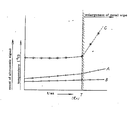
- Fig. 1 shows the Babbit metal temperature A, the oil purging temperature B and the count C of the ultrasonic signal plotted against time. These data were obtained from an experiment in which frictional wear was reproduced.
- Fig. 2 shows how the Babbit metal temperature A and the oil purging temperature B, respectively, are measured by thermocouples 13a and 13b which are provided in the Babbit metal bearing 11 and the housing 12, respectively.
- TheT.he ultrasonic signal is produced by a transducer 14 fixed to the bearing 11 and is amplified by a preamplifier 15 and a main amplifier 16, and is then counted by a counter 17.
- the Babbit metal temperature and the oil purging temperature increase monotonically before and after the occurrence of frictional wear (time T).
- the ultrasonic signal level count increased suddenly when frictional wear occurred.
- Fig. 3 illustrates a waveform of the ultrasonic signal generated by the frictional wear; the abscissa indicates time, in which T designates the point at which the onset of frictional wear occurs.
- the ultrasonic signal which appeared at about the same time has an amplitude which is approximately constant.
- the ultrasonic signal generated by the frictional wear has a characteristic period and amplitude. Accordingly, frictional wear can be detected by monitoring such an ultrasonic signal.
- a journal 20, a plain bearing 21, and a piezoelectric ceramic transducer element 22 there are shown a journal 20, a plain bearing 21, and a piezoelectric ceramic transducer element 22.
- the transducer 22 is fixed by pressure welding or bonding at a position where it receives the ultrasonic signal generated by the frictional wear on the surface of the plain bearing 21.
- the ultrasonic signal received by the transducer 22 is applied to a turning decision circuit 23 (the turning operation is the preliminary operation of the machine at a speed of about 2 rpm).
- a rotation frequency is also applied to the circuit 23.
- the turning decision circuit decides whether the machine is in turning operation or in normal operation, in order to pass the output signal of the transducer 22 to the preamplifier 24 only when the machine is in turning operation.
- the output signal of the transducer 22 is applied directly to the preamplifier 24.
- the preamplified signal is applied through a noise filter 25 to a main amplifier 26.
- the amplified signal is passed through a detector 27 and thence to a converter 28.
- the converter 28 converts the ultrasonic signal into a pulse signal.
- the pulse signal is then applied to a periodicity detection circuit 29, in which the periodicity of the pulse signal is detected.
- the output signal of the converter 28 is applied to a counter 30 when the periodicity of the pulse signal is detected, that is, when the output signal (hereinafter referred to as the frictional wear signal) of the circuit 29 indicates the occurrence of frictional wear.
- the count generated by the output sig ⁇ lal is displayed by a display 31.
- the output signal of the converter 28 is applied to a gate circuit 40, which includes a timer 41.
- a gate (A) 42a and a gate (B) 42b are operated alternately by the timer 41 so as to pass the output signal to digital memory circuits 43a and 43b, respectively.
- the digital memory circuits are constructed so that the stored signal is cleared when the next signal is input.
- the ultrasonic signal is generated periodically when the frictional wear occurs.
- the occurrence of frictional wear can be detected by computing the following ratio.
- the signals stored in the digital memory circuits 43a and 43b are applied to a divider 44 every time (t 1 , t 2 , t 3 , ...) a signal is read into the gate circuit 40.
- the ratio of the output signal A of the circuit 43a to the output signal B of the circuit 43b, that is, A 1 /B 1 , A,/B 2 , A 2 /B 2 , etc. is computed by the divider 44.
- the divider 44 outputs a direct voltage signal of 5 volts when the signal A nearly equals the signal B.
- an AND gate 45 performs an AND logical operation in response to the application of the output signal of the comparator 28 and that of the divider 44:
- Fig. 7 shows a second embodiment of the present invention.
- the same reference numerals are used for the parts corresponding to the parts shown in Fig. 4.
- Reference numeral 59 designates a microcomputer and 60 a CRT display.
- the microcomputer 59 is employed instead of the periodicity detection circuit 29 and the counter 30 shown in Fig. 4.
- the apparatus functions in a similar manner to that of Fig. 4.
Landscapes
- Physics & Mathematics (AREA)
- Biochemistry (AREA)
- Health & Medical Sciences (AREA)
- Life Sciences & Earth Sciences (AREA)
- Chemical & Material Sciences (AREA)
- Analytical Chemistry (AREA)
- Acoustics & Sound (AREA)
- General Health & Medical Sciences (AREA)
- General Physics & Mathematics (AREA)
- Immunology (AREA)
- Pathology (AREA)
- Sliding-Contact Bearings (AREA)
- Investigating Or Analyzing Materials By The Use Of Ultrasonic Waves (AREA)
- Measurement Of Mechanical Vibrations Or Ultrasonic Waves (AREA)
Claims (2)
Applications Claiming Priority (2)
| Application Number | Priority Date | Filing Date | Title |
|---|---|---|---|
| JP128918/79 | 1979-10-08 | ||
| JP12891879A JPS5653422A (en) | 1979-10-08 | 1979-10-08 | Diagnosis device for bearing abnormality |
Publications (3)
| Publication Number | Publication Date |
|---|---|
| EP0028081A2 EP0028081A2 (fr) | 1981-05-06 |
| EP0028081A3 EP0028081A3 (en) | 1982-07-07 |
| EP0028081B1 true EP0028081B1 (fr) | 1986-08-20 |
Family
ID=14996585
Family Applications (1)
| Application Number | Title | Priority Date | Filing Date |
|---|---|---|---|
| EP80303532A Expired EP0028081B1 (fr) | 1979-10-08 | 1980-10-08 | Procédé et dispositif pour détecter l'usure par friction dans des paliers métalliques |
Country Status (5)
| Country | Link |
|---|---|
| US (1) | US4481819A (fr) |
| EP (1) | EP0028081B1 (fr) |
| JP (1) | JPS5653422A (fr) |
| CA (1) | CA1162287A (fr) |
| DE (1) | DE3071710D1 (fr) |
Families Citing this family (17)
| Publication number | Priority date | Publication date | Assignee | Title |
|---|---|---|---|---|
| JPS58150859A (ja) * | 1982-03-03 | 1983-09-07 | Hitachi Ltd | 回転体の亀裂診断装置 |
| JPS5997315A (ja) * | 1982-11-24 | 1984-06-05 | Toshiba Corp | すべり軸受異常検出方法 |
| DE8432304U1 (de) * | 1984-11-05 | 1985-04-18 | Gebrüder Trox, GmbH, 4133 Neukirchen-Vluyn | Druckmessvorrichtung fuer eine klimatechnischen anlage |
| JPS6219755A (ja) * | 1985-07-19 | 1987-01-28 | Hitachi Ltd | Ae方式回転機異常診断システム |
| EP0297729B1 (fr) * | 1987-06-03 | 1992-10-21 | Koyo Seiko Co., Ltd. | Dispositif pour la détection de défauts dans des paliers |
| US4790190A (en) * | 1987-10-02 | 1988-12-13 | Servo Corporation Of America | On-line acoustic detection of bearing defects |
| US5309149A (en) * | 1992-02-12 | 1994-05-03 | The United States Of America As Represented By The Administrator Of The National Aeronautics And Space Administration | Smart accelerometer |
| SE9400568L (sv) * | 1994-02-18 | 1995-08-19 | Spm Instr International Ab | Adapter för att vid rullningslager mäta lagertillståndet |
| US5510781A (en) * | 1994-04-21 | 1996-04-23 | Ontario Hydro | Ultrasonic rotary shaft position encoder |
| DE19522543A1 (de) * | 1994-08-01 | 1996-02-08 | Ntn Toyo Bearing Co Ltd | Piezoelektrisches Film-Meßfühlersystem für Lager |
| RU2213336C2 (ru) * | 2001-06-25 | 2003-09-27 | Хабаровский государственный технический университет | Способ ультразвукового контроля подшипников качения |
| DE10324924B4 (de) * | 2003-06-03 | 2021-08-26 | Ab Skf | Verfahren zum Ermitteln einer von einem Gleitlager mit sphärisch oder zylindrisch ausgebildeten Lagerflächen aufgenommenen Last |
| US7509862B2 (en) * | 2007-01-24 | 2009-03-31 | Massachusetts Institute Of Technology | System and method for providing vibration detection in turbomachinery |
| GB2491632B (en) * | 2011-06-10 | 2013-10-30 | Rolls Royce Plc | Rotating blade analysis |
| EP2805072A1 (fr) * | 2012-04-19 | 2014-11-26 | Siemens Aktiengesellschaft | Procédé et dispositif de mesure pour contrôler des états de fonctionnement d'un palier lisse |
| US9927323B2 (en) * | 2012-10-26 | 2018-03-27 | Acellent Technologies, Inc. | System and method for monitoring the structural health of coupled bearings |
| CN109084981B (zh) * | 2018-10-22 | 2020-04-03 | 中国矿业大学 | 一种轴承冲击摩擦磨损试验机 |
Family Cites Families (10)
| Publication number | Priority date | Publication date | Assignee | Title |
|---|---|---|---|---|
| US2114029A (en) * | 1936-09-29 | 1938-04-12 | Socony Vacuum Oil Co Inc | Testing machine |
| US3052123A (en) * | 1959-05-21 | 1962-09-04 | Robert E Gustafson | Temperature sensing element and method of installation |
| US3699806A (en) * | 1967-07-14 | 1972-10-24 | Bjorn Weichbrodt | Early detection of damage to machine elements in rolling engagement |
| US3677072A (en) * | 1970-10-30 | 1972-07-18 | Gen Electric | Damage detection method and apparatus for machine elements utilizing vibrations therefrom |
| US3712130A (en) * | 1970-10-30 | 1973-01-23 | Gen Electric | Detection of distributed defects in gear assemblies |
| US3842663A (en) * | 1972-12-01 | 1974-10-22 | Boeing Co | Demodulated resonance analysis system |
| JPS599842B2 (ja) * | 1974-07-12 | 1984-03-05 | 日本精工株式会社 | 回転体の損傷検出装置 |
| US3971249A (en) * | 1975-03-28 | 1976-07-27 | Sun Oil Company Of Pennsylvania | Mechanical testing system |
| NL7704347A (nl) * | 1977-04-21 | 1978-10-24 | Skf Ind Trading & Dev | Detectie-systeem alsmede detectie-apparaat waarin het systeem is aangebracht. |
| JPS54149696A (en) * | 1978-05-16 | 1979-11-24 | Hitachi Ltd | Rubbing detection between rotary body and stationary body |
-
1979
- 1979-10-08 JP JP12891879A patent/JPS5653422A/ja active Pending
-
1980
- 1980-10-08 CA CA000361812A patent/CA1162287A/fr not_active Expired
- 1980-10-08 EP EP80303532A patent/EP0028081B1/fr not_active Expired
- 1980-10-08 DE DE8080303532T patent/DE3071710D1/de not_active Expired
-
1983
- 1983-02-09 US US06/465,183 patent/US4481819A/en not_active Expired - Fee Related
Also Published As
| Publication number | Publication date |
|---|---|
| EP0028081A3 (en) | 1982-07-07 |
| EP0028081A2 (fr) | 1981-05-06 |
| CA1162287A (fr) | 1984-02-14 |
| JPS5653422A (en) | 1981-05-13 |
| DE3071710D1 (en) | 1986-09-25 |
| US4481819A (en) | 1984-11-13 |
Similar Documents
| Publication | Publication Date | Title |
|---|---|---|
| EP0028081B1 (fr) | Procédé et dispositif pour détecter l'usure par friction dans des paliers métalliques | |
| US4669315A (en) | Rotating machinery diagnosis system with acoustic emission technique | |
| CA1195418A (fr) | Methode et dispositif de detection des frottements dans une mahine tournante | |
| US4748850A (en) | Apparatus for evaluating the slippage of a mechanical seal | |
| US5511422A (en) | Method and apparatus for analyzing and detecting faults in bearings and other rotating components that slip | |
| JP2935503B2 (ja) | タービン羽根の振動を検知する方法および装置 | |
| US4991442A (en) | Method and apparatus for detecting cracks in bearings | |
| CA1179064A (fr) | Methode d'analyse des vibrations d'une machine tournante | |
| US4377947A (en) | Device for identifying rubbing locations in rotating machines | |
| US5747680A (en) | Multiple parameter sensor and method of operation thereof | |
| JPS60195426A (ja) | 回転機構の故障診断方法 | |
| JP2695366B2 (ja) | 低速回転機械の異常診断方法 | |
| JP3318246B2 (ja) | ファンモータ診断方法及び診断装置 | |
| JPH0619291B2 (ja) | 回転機械の振動監視装置 | |
| JP3264480B2 (ja) | 軸受内蔵型車輪及び低速回転軸受の異常診断方法 | |
| JP2551119B2 (ja) | 軸振動自己診断装置 | |
| JPH0565016B2 (fr) | ||
| JPS61128128A (ja) | 回転体の異常診断装置 | |
| JP2963144B2 (ja) | 軸受の異常検出装置 | |
| JPS59212512A (ja) | すべり軸受の監視方法 | |
| JP2596885B2 (ja) | 回転機械の開放型羽根の振れ監視装置 | |
| JPS6330983Y2 (fr) | ||
| JPS61182530A (ja) | 捩り振動検出装置 | |
| JPS644611B2 (fr) | ||
| JPS6131325B2 (fr) |
Legal Events
| Date | Code | Title | Description |
|---|---|---|---|
| PUAI | Public reference made under article 153(3) epc to a published international application that has entered the european phase |
Free format text: ORIGINAL CODE: 0009012 |
|
| 17P | Request for examination filed |
Effective date: 19810113 |
|
| AK | Designated contracting states |
Designated state(s): DE FR SE |
|
| PUAL | Search report despatched |
Free format text: ORIGINAL CODE: 0009013 |
|
| AK | Designated contracting states |
Designated state(s): DE FR SE |
|
| GRAA | (expected) grant |
Free format text: ORIGINAL CODE: 0009210 |
|
| AK | Designated contracting states |
Kind code of ref document: B1 Designated state(s): DE FR SE |
|
| REF | Corresponds to: |
Ref document number: 3071710 Country of ref document: DE Date of ref document: 19860925 |
|
| ET | Fr: translation filed | ||
| PLBE | No opposition filed within time limit |
Free format text: ORIGINAL CODE: 0009261 |
|
| STAA | Information on the status of an ep patent application or granted ep patent |
Free format text: STATUS: NO OPPOSITION FILED WITHIN TIME LIMIT |
|
| 26N | No opposition filed | ||
| PGFP | Annual fee paid to national office [announced via postgrant information from national office to epo] |
Ref country code: SE Payment date: 19930909 Year of fee payment: 14 |
|
| PGFP | Annual fee paid to national office [announced via postgrant information from national office to epo] |
Ref country code: FR Payment date: 19931018 Year of fee payment: 14 |
|
| PGFP | Annual fee paid to national office [announced via postgrant information from national office to epo] |
Ref country code: DE Payment date: 19931223 Year of fee payment: 14 |
|
| PG25 | Lapsed in a contracting state [announced via postgrant information from national office to epo] |
Ref country code: SE Effective date: 19941009 |
|
| EAL | Se: european patent in force in sweden |
Ref document number: 80303532.8 |
|
| PG25 | Lapsed in a contracting state [announced via postgrant information from national office to epo] |
Ref country code: FR Effective date: 19950630 |
|
| PG25 | Lapsed in a contracting state [announced via postgrant information from national office to epo] |
Ref country code: DE Effective date: 19950701 |
|
| EUG | Se: european patent has lapsed |
Ref document number: 80303532.8 |
|
| REG | Reference to a national code |
Ref country code: FR Ref legal event code: ST |