EP0028112B1 - Strip for forming a solar panel - Google Patents
Strip for forming a solar panel Download PDFInfo
- Publication number
- EP0028112B1 EP0028112B1 EP80303693A EP80303693A EP0028112B1 EP 0028112 B1 EP0028112 B1 EP 0028112B1 EP 80303693 A EP80303693 A EP 80303693A EP 80303693 A EP80303693 A EP 80303693A EP 0028112 B1 EP0028112 B1 EP 0028112B1
- Authority
- EP
- European Patent Office
- Prior art keywords
- strip
- flange
- channel
- conduit
- flanges
- Prior art date
- Legal status (The legal status is an assumption and is not a legal conclusion. Google has not performed a legal analysis and makes no representation as to the accuracy of the status listed.)
- Expired
Links
- 239000000463 material Substances 0.000 claims description 17
- 230000015572 biosynthetic process Effects 0.000 claims description 8
- 210000001364 upper extremity Anatomy 0.000 claims description 4
- 239000013529 heat transfer fluid Substances 0.000 claims description 3
- 239000011358 absorbing material Substances 0.000 claims description 2
- 230000000295 complement effect Effects 0.000 claims description 2
- 238000000926 separation method Methods 0.000 claims 1
- 238000005728 strengthening Methods 0.000 claims 1
- 238000005755 formation reaction Methods 0.000 description 5
- 238000000034 method Methods 0.000 description 5
- 238000001125 extrusion Methods 0.000 description 3
- 238000004519 manufacturing process Methods 0.000 description 3
- 239000002184 metal Substances 0.000 description 3
- 229910052751 metal Inorganic materials 0.000 description 3
- RYGMFSIKBFXOCR-UHFFFAOYSA-N Copper Chemical compound [Cu] RYGMFSIKBFXOCR-UHFFFAOYSA-N 0.000 description 2
- 239000011324 bead Substances 0.000 description 2
- 229910052802 copper Inorganic materials 0.000 description 2
- 239000010949 copper Substances 0.000 description 2
- 230000000135 prohibitive effect Effects 0.000 description 2
- 238000003466 welding Methods 0.000 description 2
- 229910001209 Low-carbon steel Inorganic materials 0.000 description 1
- XUIMIQQOPSSXEZ-UHFFFAOYSA-N Silicon Chemical compound [Si] XUIMIQQOPSSXEZ-UHFFFAOYSA-N 0.000 description 1
- 230000002745 absorbent Effects 0.000 description 1
- 239000002250 absorbent Substances 0.000 description 1
- 238000006243 chemical reaction Methods 0.000 description 1
- 238000010276 construction Methods 0.000 description 1
- 238000005260 corrosion Methods 0.000 description 1
- 230000007797 corrosion Effects 0.000 description 1
- 238000002788 crimping Methods 0.000 description 1
- 239000012530 fluid Substances 0.000 description 1
- 230000006698 induction Effects 0.000 description 1
- 238000003780 insertion Methods 0.000 description 1
- 230000037431 insertion Effects 0.000 description 1
- 239000013521 mastic Substances 0.000 description 1
- 238000012986 modification Methods 0.000 description 1
- 230000004048 modification Effects 0.000 description 1
- 230000002093 peripheral effect Effects 0.000 description 1
- 230000001681 protective effect Effects 0.000 description 1
- 229910052710 silicon Inorganic materials 0.000 description 1
- 239000010703 silicon Substances 0.000 description 1
- 230000009182 swimming Effects 0.000 description 1
Images
Classifications
-
- F—MECHANICAL ENGINEERING; LIGHTING; HEATING; WEAPONS; BLASTING
- F24—HEATING; RANGES; VENTILATING
- F24S—SOLAR HEAT COLLECTORS; SOLAR HEAT SYSTEMS
- F24S10/00—Solar heat collectors using working fluids
- F24S10/70—Solar heat collectors using working fluids the working fluids being conveyed through tubular absorbing conduits
- F24S10/75—Solar heat collectors using working fluids the working fluids being conveyed through tubular absorbing conduits with enlarged surfaces, e.g. with protrusions or corrugations
- F24S10/753—Solar heat collectors using working fluids the working fluids being conveyed through tubular absorbing conduits with enlarged surfaces, e.g. with protrusions or corrugations the conduits being parallel to each other
-
- F—MECHANICAL ENGINEERING; LIGHTING; HEATING; WEAPONS; BLASTING
- F24—HEATING; RANGES; VENTILATING
- F24S—SOLAR HEAT COLLECTORS; SOLAR HEAT SYSTEMS
- F24S20/00—Solar heat collectors specially adapted for particular uses or environments
- F24S20/60—Solar heat collectors integrated in fixed constructions, e.g. in buildings
- F24S20/67—Solar heat collectors integrated in fixed constructions, e.g. in buildings in the form of roof constructions
-
- Y—GENERAL TAGGING OF NEW TECHNOLOGICAL DEVELOPMENTS; GENERAL TAGGING OF CROSS-SECTIONAL TECHNOLOGIES SPANNING OVER SEVERAL SECTIONS OF THE IPC; TECHNICAL SUBJECTS COVERED BY FORMER USPC CROSS-REFERENCE ART COLLECTIONS [XRACs] AND DIGESTS
- Y02—TECHNOLOGIES OR APPLICATIONS FOR MITIGATION OR ADAPTATION AGAINST CLIMATE CHANGE
- Y02B—CLIMATE CHANGE MITIGATION TECHNOLOGIES RELATED TO BUILDINGS, e.g. HOUSING, HOUSE APPLIANCES OR RELATED END-USER APPLICATIONS
- Y02B10/00—Integration of renewable energy sources in buildings
- Y02B10/20—Solar thermal
-
- Y—GENERAL TAGGING OF NEW TECHNOLOGICAL DEVELOPMENTS; GENERAL TAGGING OF CROSS-SECTIONAL TECHNOLOGIES SPANNING OVER SEVERAL SECTIONS OF THE IPC; TECHNICAL SUBJECTS COVERED BY FORMER USPC CROSS-REFERENCE ART COLLECTIONS [XRACs] AND DIGESTS
- Y02—TECHNOLOGIES OR APPLICATIONS FOR MITIGATION OR ADAPTATION AGAINST CLIMATE CHANGE
- Y02E—REDUCTION OF GREENHOUSE GAS [GHG] EMISSIONS, RELATED TO ENERGY GENERATION, TRANSMISSION OR DISTRIBUTION
- Y02E10/00—Energy generation through renewable energy sources
- Y02E10/40—Solar thermal energy, e.g. solar towers
- Y02E10/44—Heat exchange systems
Definitions
- This invention relates to a strip for forming a combined solar energy collecting and roofing panel which can be used for collecting and transferring solar energy to a heat transfer medium.
- the general object of the present invention is to provide a strip of material of novel configuration which can be used for forming a solar collecting panel and additionally has sufficient structural strength that it can be used as a roofing material.
- United States Patent No. 4,111,185 disclosed another arrangement utilising corrugated roofing material having heat transfer conduits cemented between adjacent corrugations. The material is covered by an energy transparent medium to reduce heat losses. The arrangement appears to be such that it would require almost total fabrication on site and would therefore be relatively expensive.
- United States Patent No. 4,111,188 discloses another arrangement which utilises shingles which are formed from extruded material and it is believed that the cost of manufacturing and installing such extruded shingles would be prohibitive.
- West German Patent Application No. 2,808,724 shows a heat metal roof structure as strips with raised interlocking side flanges and with low-level part-circular-section folded bead formations running along the flat decks of the panels to house thermal fluid conduits, these bead formations projecting only slightly above the level of the flat decks to which they are directly joined.
- Such a construction suffers the disadvantage that the solar energy collecting efficiency of the arrangement tends to be low, especially at times of low elevation of the sun above the horizon.
- United States Patent No. 4,164,932 concerns an alternative arrangement using complicated metal extrusions which cooperate to hold copper conduits therebetween. Again, it is thought that the cost of the extrusions would be prohibitive.
- the object of the present invention is to provide a strip material which is appropriately formed so that it interlocks with heat transfer conduits and moreover adjacent strips interlock with one another to form a viable roofing material.
- the invention provides a strip for forming a combined solar energy collecting and roofing panel, the strip being formed from sheet material and having a base with a generally flat upper side and with first and second flanges extending longitudinally on opposite marginal edges of the strip, and projecting upwardly from the base, which flanges are of generally complementary shape so that the first flange can interlock with the second flange of a similar strip whereby a plurality of the strips can be interlocked together to form said combined panel, and the strip being formed with a longitudinally-extending strip raised formation intermediate of the first and second flanges which raised formation projects upwardly from the flat upper side of the base and defines an elongate channel which is open to the lower side of the strip for receiving in use a conduit for a heat-transfer fluid, characterised in that the longitudinally-extending raised formation includes longitudinally-extending side wall portions which are oppositely-inclined width wise to the flat upper side of the base and are generally perpendicular to one another and are joined together along their adjacent upper longitudinal edges by the channel
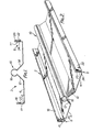
- the strip 2 of the invention is preferably roll formed from 26 gauge galvanised mild steel sheet into the configuration illustrated in Figure 1.
- the strip has a base 4 and first and second elongate side flanges 6 and 8.
- the strip is formed with a central projecting portion 10 which includes first and second inclined surfaces 12 and 14, which are directed towards one another and are inclined at approximately 45° to the base 4.
- the upper edges of the inclined surfaces 12 and 14 are joined by a continuous part-circular channel portion 16, the portion 16 extending approximately 270° about its centre.
- the first flange 6 includes an upturned portion 17 and a downturned portion 18 the lower edge of which defines a shoulder 20.
- the second flange 8 includes an upturned portion 21, a first downturned portion 22 which defines with the upturned portion 21 an inverted channel section and an upturned peripheral portion 24 which defines an upwardly facing shoulder 26 within the said inverted channel.
- the flanges 6 of one strip can be inserted into the channels formed at the second flanges 8 of adjacent strips whereby the strips are interlocked together to form a solar collecting panel.
- the shoulders 20 and 26 of the flanges 6 and 8 abut one another and maintain the strips interlocked together.
- the interlocking arrangement would be weatherproof and thus the panels are suitable for use as roofing material.
- To improve the efficiency of the strips as solar panels it is desirable to coat the outer surface with known solar energy absorptive coverings.
- the inclined surfaces 12 and 14 are especially suitable for receiving solar energy at those times when the sun is low in the sky.
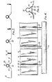
- the configuration of the channel portion 16 is such . that it establishes a relatively large area of thermal contact with conduits 28 which are located therein, as seen in Figures 3 and 4.
- the conduits 28 are preferably formed from copper tube and have an outer diameter which approximately equals the inner diameter of the channels 16 and are slid into the channels 16 from ends thereof. Once the conduits are located in the channels the openings of the channels are sealed against the conduits and against the lower faces of the inclined surfaces 12 and 14 to prevent moisture entering any gaps between the conduits 28 and the channel 16 since otherwise this region would be susceptible to corrosion.
- a commercially available silicon mastic is suitable for this purpose and is applied in a fillet 30 as illustrated in Figure 3.
- conduits 28 are preferably connected to header tubes 31 as illustrated in Figure 4 for circulation of a suitable heat transfer fluid which is heated indirectly by the solar energy received by the strip 2.
- the arrangement illustrated in Figure 5 is generally similar to the strip illustrated in Figure 1 except that the inclined surfaces 12 and 14 include longitudinally extending grooves 32 and 34.
- the grooves 32 and 34 serve to strengthen the strip and additionally permit the insertion of a protective strip 36 which serves to shield the rear face of the conduit 28 which would otherwise be exposed.
- the arrangement illustrated in Figure 5 is particularly suited to an alternative use of the strip in fences, especially fences surrounding swimming pools and the like.
Landscapes
- Engineering & Computer Science (AREA)
- Chemical & Material Sciences (AREA)
- Physics & Mathematics (AREA)
- Life Sciences & Earth Sciences (AREA)
- Sustainable Development (AREA)
- Sustainable Energy (AREA)
- Thermal Sciences (AREA)
- Combustion & Propulsion (AREA)
- Mechanical Engineering (AREA)
- General Engineering & Computer Science (AREA)
- Dispersion Chemistry (AREA)
- Roof Covering Using Slabs Or Stiff Sheets (AREA)
Description
- This invention relates to a strip for forming a combined solar energy collecting and roofing panel which can be used for collecting and transferring solar energy to a heat transfer medium.
- The general object of the present invention is to provide a strip of material of novel configuration which can be used for forming a solar collecting panel and additionally has sufficient structural strength that it can be used as a roofing material.
- A search of prior publications has revealed a number of previous attempts to provide a solar energy panel which can additionally function as a roofing material. These arrangements are however somewhat complicated and thus would be relatively expensive to manufacture. For instance, United States Patent No. 4,178,912 discloses an arrangement comprising roofing material in the form of a relatively deep trough within which are located a number of heat transfer conduits. The arrangement suffers the disadvantage that the sides of the trough would shade the energy absorbent surfaces at low angles of incidence of the sun and therefore reduce the effectiveness of the material. Further, the techniques suggested for forming the heat transfer conduit appear to be cumbersome.
- United States Patent No. 4,111,185 disclosed another arrangement utilising corrugated roofing material having heat transfer conduits cemented between adjacent corrugations. The material is covered by an energy transparent medium to reduce heat losses. The arrangement appears to be such that it would require almost total fabrication on site and would therefore be relatively expensive.
- United States Patent No. 4,111,188 discloses another arrangement which utilises shingles which are formed from extruded material and it is believed that the cost of manufacturing and installing such extruded shingles would be prohibitive.
- West German Patent Application No. 2,808,724 shows a heat metal roof structure as strips with raised interlocking side flanges and with low-level part-circular-section folded bead formations running along the flat decks of the panels to house thermal fluid conduits, these bead formations projecting only slightly above the level of the flat decks to which they are directly joined. Such a construction suffers the disadvantage that the solar energy collecting efficiency of the arrangement tends to be low, especially at times of low elevation of the sun above the horizon.
- Other attempts in the prior art have been concerned with alternative techniques of making solar energy absorbing panels which do not form roofing material. For instance, United States Patent No. 4,136,272 discloses a technique for induction welding heat transfer conduits to strip material. It is thought that the welding technique would be relatively expensive, and moreover the method of crimping adjacent edges of strips together is unsuitable for roofing applications. Further, there is no provision for providing solar energy collecting areas at low incident angles of the sun, other than the area of the heat transfer tubes themselves.
- United States Patent Nos. 4,114,598 and 4,144,874 disclose solar energy conversion panels which utilize extruded members of complicated configuration. It is thought that the cost of the extrusions would prevent widespread application of these proposals.
- United States Patent No. 4,164,932 concerns an alternative arrangement using complicated metal extrusions which cooperate to hold copper conduits therebetween. Again, it is thought that the cost of the extrusions would be prohibitive.
- United States Patent Nos. 3,972,317 and 4,011,856 disclose arrangements in which formed sheet metal is used to mechanically interlock with heat transfer conduits. However, in both patents the arrangements are such that the material would be quite unsuited for use as a roofing material and moreover there is no provision for collection of solar energy at large angles of incidence of the sun.
- Generally speaking, the object of the present invention is to provide a strip material which is appropriately formed so that it interlocks with heat transfer conduits and moreover adjacent strips interlock with one another to form a viable roofing material.
- More specifically, the invention provides a strip for forming a combined solar energy collecting and roofing panel, the strip being formed from sheet material and having a base with a generally flat upper side and with first and second flanges extending longitudinally on opposite marginal edges of the strip, and projecting upwardly from the base, which flanges are of generally complementary shape so that the first flange can interlock with the second flange of a similar strip whereby a plurality of the strips can be interlocked together to form said combined panel, and the strip being formed with a longitudinally-extending strip raised formation intermediate of the first and second flanges which raised formation projects upwardly from the flat upper side of the base and defines an elongate channel which is open to the lower side of the strip for receiving in use a conduit for a heat-transfer fluid, characterised in that the longitudinally-extending raised formation includes longitudinally-extending side wall portions which are oppositely-inclined width wise to the flat upper side of the base and are generally perpendicular to one another and are joined together along their adjacent upper longitudinal edges by the channel, which channel is shaped to receive and snugly engage said conduit around more than approximately 225° of the circumference thereof, the upper extremity of the channel being located at a greater distance from the plane of the flat upper side of the base than are the upper extremities of the first and second flanges and the upper side of the strip being coated with solar energy-absorbing material.
- The invention may be carried into practice in various ways, but certain specific embodiments thereof will now be described by way of example only and with reference to the accompanying drawings, in which:-
- Figure 1 is a cross-section through a preferred form of strip embodying the invention;
- Figure 2 is a perspective view of the strip of Figure 1;
- Figure 3 is a cross-section through a number of said strips interlocked together at their side edges to form a solar collecting panel;
- Figure 4 is a plane view of a solar collecting panel constructed as shown in Figure 3; and
- Figure 5 shows a slight modification of the strip shown in Figure 1.
- The
strip 2 of the invention is preferably roll formed from 26 gauge galvanised mild steel sheet into the configuration illustrated in Figure 1. In particular the strip has abase 4 and first and secondelongate side flanges central projecting portion 10 which includes first and secondinclined surfaces base 4. The upper edges of theinclined surfaces circular channel portion 16, theportion 16 extending approximately 270° about its centre. Thefirst flange 6 includes anupturned portion 17 and adownturned portion 18 the lower edge of which defines ashoulder 20. Thesecond flange 8 includes anupturned portion 21, a firstdownturned portion 22 which defines with theupturned portion 21 an inverted channel section and an upturnedperipheral portion 24 which defines an upwardly facingshoulder 26 within the said inverted channel. As best illustrated in Figure 3 theflanges 6 of one strip can be inserted into the channels formed at thesecond flanges 8 of adjacent strips whereby the strips are interlocked together to form a solar collecting panel. Theshoulders flanges - The
inclined surfaces channel portion 16 is such . that it establishes a relatively large area of thermal contact withconduits 28 which are located therein, as seen in Figures 3 and 4. Theconduits 28 are preferably formed from copper tube and have an outer diameter which approximately equals the inner diameter of thechannels 16 and are slid into thechannels 16 from ends thereof. Once the conduits are located in the channels the openings of the channels are sealed against the conduits and against the lower faces of theinclined surfaces conduits 28 and thechannel 16 since otherwise this region would be susceptible to corrosion. A commercially available silicon mastic is suitable for this purpose and is applied in afillet 30 as illustrated in Figure 3. - The upper and lower ends of the
conduits 28 are preferably connected toheader tubes 31 as illustrated in Figure 4 for circulation of a suitable heat transfer fluid which is heated indirectly by the solar energy received by thestrip 2. - The arrangement illustrated in Figure 5 is generally similar to the strip illustrated in Figure 1 except that the
inclined surfaces grooves grooves protective strip 36 which serves to shield the rear face of theconduit 28 which would otherwise be exposed. The arrangement illustrated in Figure 5 is particularly suited to an alternative use of the strip in fences, especially fences surrounding swimming pools and the like.
Claims (8)
Applications Claiming Priority (2)
| Application Number | Priority Date | Filing Date | Title |
|---|---|---|---|
| AU1035/79 | 1979-10-23 | ||
| AU103579 | 1979-10-23 |
Publications (2)
| Publication Number | Publication Date |
|---|---|
| EP0028112A1 EP0028112A1 (en) | 1981-05-06 |
| EP0028112B1 true EP0028112B1 (en) | 1984-09-12 |
Family
ID=3691668
Family Applications (1)
| Application Number | Title | Priority Date | Filing Date |
|---|---|---|---|
| EP80303693A Expired EP0028112B1 (en) | 1979-10-23 | 1980-10-20 | Strip for forming a solar panel |
Country Status (6)
| Country | Link |
|---|---|
| US (1) | US4336793A (en) |
| EP (1) | EP0028112B1 (en) |
| JP (1) | JPS56105255A (en) |
| AU (1) | AU534683B2 (en) |
| CA (1) | CA1162805A (en) |
| PH (1) | PH16990A (en) |
Cited By (1)
| Publication number | Priority date | Publication date | Assignee | Title |
|---|---|---|---|---|
| DE19710915C1 (en) * | 1997-03-15 | 1998-08-27 | Viessmann Werke Kg | Collector for absorbing solar and ambient energy |
Families Citing this family (32)
| Publication number | Priority date | Publication date | Assignee | Title |
|---|---|---|---|---|
| EP0026808B1 (en) * | 1979-08-30 | 1983-12-21 | Kabel- und Metallwerke Gutehoffnungshütte Aktiengesellschaft | Roof covering or façade lining and method for the manufacture of a panel for this roof covering or façade lining |
| JPS58142649U (en) * | 1982-03-19 | 1983-09-26 | セイレイ工業株式会社 | solar heat collector |
| FR2535032B1 (en) * | 1982-10-25 | 1987-12-11 | Ladriere Serge | INSULATOR WITH VERTICAL ANGULAR ABSORBER |
| EP0330701A3 (en) * | 1984-09-18 | 1989-10-04 | Sharp Kabushiki Kaisha | Heat collector |
| CA1265398A (en) * | 1984-11-01 | 1990-02-06 | Barrie Peter Moore | Roof installations |
| US4750473A (en) * | 1985-01-23 | 1988-06-14 | Ritelite Pty. Ltd. | Light controlling heat collecting solar roof |
| DE19506620C2 (en) * | 1995-02-25 | 1999-04-01 | Michael Prof Schoenherr | Solar module for converting radiation energy into thermal energy |
| DE19600579C1 (en) * | 1996-01-10 | 1997-04-10 | Viessmann Gmbh & Co | Roofing element, to utilise solar heat for cooling or air conditioning |
| DE19741277A1 (en) * | 1997-09-19 | 1999-04-01 | Viessmann Werke Kg | Solar panel |
| BE1011529A3 (en) * | 1997-11-04 | 1999-10-05 | Solel Consumer Naamloze Vennoo | Device for reflect of solar radiation. |
| ES2151450B1 (en) * | 1999-03-23 | 2001-06-16 | Biohabitat Sxxi Sl | SOLAR ENERGY COLLECTION COVER FOR BUILDINGS AND INTEGRATING PANEL OF THE SAME. |
| ATE280368T1 (en) * | 1998-06-03 | 2004-11-15 | Biohabitat Sxxi S L | BUILDING ROOF FOR USING SOLAR ENERGY AND ASSOCIATED PANEL |
| DK79298A (en) * | 1998-06-08 | 1999-12-09 | Norsk Hydro As | Profile of fuel cooling, a fuel line and a process for making them |
| DE20216297U1 (en) * | 2002-10-23 | 2003-01-09 | Rheinzink GmbH & Co. KG, 45711 Datteln | Heliothermal flat collector module in sandwich construction |
| PL209166B1 (en) * | 2005-04-04 | 2011-07-29 | Dariusz Dżegan | Building panel |
| US20070056579A1 (en) * | 2005-09-09 | 2007-03-15 | Straka Christopher W | Energy Channeling Sun Shade System and Apparatus |
| US8875454B2 (en) * | 2006-06-19 | 2014-11-04 | Daniel Efrain Arguelles | Pan tile roofing system |
| US8468756B2 (en) * | 2006-06-19 | 2013-06-25 | Daniel Efrain Arguelles | Pan tile roofing system |
| US9663955B2 (en) * | 2006-06-19 | 2017-05-30 | Daniel Efrain Arguelles | Pan tile roofing system |
| WO2008019441A1 (en) * | 2006-08-17 | 2008-02-21 | Panel D (Nz) Limited | Method of manufacturing trailers |
| US20080083176A1 (en) * | 2006-10-06 | 2008-04-10 | Davis Energy Group, Inc. | Roofing panel |
| US7971586B2 (en) * | 2006-12-13 | 2011-07-05 | Hanken Michael J | Solar heating system and method of forming a panel assembly therefor |
| US8256690B2 (en) * | 2007-04-27 | 2012-09-04 | Talbott Solar And Radiant Homes, Inc. | Radiant heating and cooling panel |
| AT509380B1 (en) * | 2010-01-18 | 2012-04-15 | Bartelmuss Klaus Ing | ENERGY COLLECTOR WITH AT LEAST ONE THERMAL AND ONE PHOTOVOLTAIC COLLECTOR |
| ZA201100688B (en) * | 2010-01-29 | 2013-03-27 | Aqua Filter (Pty) Ltd | Solar heat collecting device |
| US20120067868A1 (en) * | 2010-08-16 | 2012-03-22 | Brian Casey | Heating system and method of making and use |
| GB2484518A (en) * | 2010-10-14 | 2012-04-18 | Phillip James Sylvester | Solar collector system comprising overlapping collector panels forming a roof structure |
| ES2381698B1 (en) * | 2010-11-03 | 2012-12-21 | Abengoa Solar New Technologies S.A. | SOLAR COLLECTOR WITH MULTITUBULAR RECEIVER, THERMOSOLAR PLANTS CONTAINING SUCH COLLECTOR AND METHOD OF OPERATION OF SUCH PLANTS. |
| TWI431232B (en) * | 2011-07-04 | 2014-03-21 | Univ Nat Pingtung Sci & Tech | Solar heat transfer apparatus |
| CN103212963A (en) * | 2013-05-15 | 2013-07-24 | 江苏奥蓝光热科技有限公司 | Method for manufacturing heat-absorbing body of aluminum alloy strip flat plate solar collector |
| AT518986B1 (en) * | 2016-10-07 | 2018-03-15 | Dipl Ing Thomas Euler Rolle | heat exchangers |
| US11035130B1 (en) | 2019-02-01 | 2021-06-15 | Daniel Efrain Arguelles | Synthetic mechanically attached roof underlayment system |
Family Cites Families (22)
| Publication number | Priority date | Publication date | Assignee | Title |
|---|---|---|---|---|
| DE591661C (en) | 1932-07-18 | 1934-01-24 | Camera Projectors Ltd | Cinematographic device |
| US3366170A (en) * | 1966-01-25 | 1968-01-30 | Hans Joachim Welz | Heat exchanger including diffusing element |
| US3384167A (en) * | 1967-04-03 | 1968-05-21 | Javkin Simon | Band for heat exchange |
| AU478911B2 (en) * | 1972-04-17 | 1974-10-17 | Robot Trading Co. Pty. Ltd | Roof decking or wall cladding sheet and structures incorporating same |
| US4011856A (en) * | 1975-03-28 | 1977-03-15 | Energy Systems, Inc. | Solar fluid heater |
| GB1551366A (en) * | 1975-04-30 | 1979-08-30 | Leeuwen E Van | Solar heat exchange device |
| US3972317A (en) * | 1975-05-12 | 1976-08-03 | Energy Systems, Inc. | Solar fluid heater |
| CH591661A5 (en) * | 1975-09-29 | 1977-09-30 | Swisspor Ag | |
| US4111185A (en) * | 1976-03-29 | 1978-09-05 | Swann Frederick R | Solar heating system |
| US4111188A (en) * | 1976-04-06 | 1978-09-05 | Murphy Jr John A | Extruded metal solar collector roofing shingle |
| AU504928B2 (en) | 1976-07-29 | 1979-11-01 | Showa Aluminium K.K. | Solar heat collector |
| GB1541577A (en) * | 1976-10-06 | 1979-03-07 | Solar Apparatus & Equipment | Solar heating panels |
| US4164932A (en) * | 1976-12-15 | 1979-08-21 | Grumman Corporation | Solar heat collector construction |
| DE7705030U1 (en) | 1977-02-18 | 1977-10-13 | Pan-Therm Gmbh Gesellschaft Fuer Planung, Herstellung Und Vertrieb Energiesparender Heizungsanlagen, 8411 Waldetzenberg | COMPONENT KIT FOR A FLAT AIR CONDITIONING DEVICE |
| DE2712532A1 (en) | 1977-03-22 | 1978-09-28 | Pantherm Gmbh | Solar heating module - with carrier element for transparent panes and heat recovery panels enclosing tubes for heating medium |
| US4136272A (en) * | 1977-04-25 | 1979-01-23 | Thermatool Corporation | Method of manufacturing heat exchange panels |
| US4144874A (en) * | 1977-06-10 | 1979-03-20 | Sunhouse, Incorporated | Solar panel |
| US4178912A (en) * | 1977-08-09 | 1979-12-18 | Felter John V | Solar heating system |
| DE2808723A1 (en) | 1978-03-01 | 1979-09-06 | Rigips Baustoffwerke Gmbh | BUILDING PLATE MADE OF PLASTER WITH A COATING OF GLASS FIBER |
| DE2808724A1 (en) * | 1978-03-01 | 1979-09-06 | Kabel Metallwerke Ghh | Atmosphere heat collecting metal ribbed roof panels - have fluid-filled tubes in heat conductive contact and retained by stirrup pieces |
| US4221208A (en) * | 1978-11-28 | 1980-09-09 | Murphy Jr John A | Solar collector assembly |
| DE7904356U1 (en) | 1979-02-17 | 1979-08-23 | Landgrebe, Heinrich, 3501 Schauenburg | SOLAR HEATING DEVICE |
-
1979
- 1979-10-23 AU AU63123/80A patent/AU534683B2/en not_active Expired
-
1980
- 1980-10-16 US US06/197,435 patent/US4336793A/en not_active Expired - Lifetime
- 1980-10-20 PH PH24745A patent/PH16990A/en unknown
- 1980-10-20 EP EP80303693A patent/EP0028112B1/en not_active Expired
- 1980-10-22 CA CA000363016A patent/CA1162805A/en not_active Expired
- 1980-10-23 JP JP14886680A patent/JPS56105255A/en active Pending
Cited By (1)
| Publication number | Priority date | Publication date | Assignee | Title |
|---|---|---|---|---|
| DE19710915C1 (en) * | 1997-03-15 | 1998-08-27 | Viessmann Werke Kg | Collector for absorbing solar and ambient energy |
Also Published As
| Publication number | Publication date |
|---|---|
| JPS56105255A (en) | 1981-08-21 |
| PH16990A (en) | 1984-05-04 |
| EP0028112A1 (en) | 1981-05-06 |
| AU6312380A (en) | 1981-05-14 |
| AU534683B2 (en) | 1984-02-09 |
| US4336793A (en) | 1982-06-29 |
| CA1162805A (en) | 1984-02-28 |
Similar Documents
| Publication | Publication Date | Title |
|---|---|---|
| EP0028112B1 (en) | Strip for forming a solar panel | |
| AU575222B2 (en) | Interfitting roof members incorporating heat pipes | |
| US4112921A (en) | Method and system for utilizing a flexible tubing solar collector | |
| US4237861A (en) | Solar energy collector used as roof member | |
| GB1573294A (en) | Facing or roof covering | |
| US4212291A (en) | Batten for mounting a unitary solar collector panel | |
| US4271823A (en) | Unitary solar collector panel | |
| US4409960A (en) | Louver solar panel | |
| US4252103A (en) | Frame structure for a solar heating panel | |
| US4245621A (en) | Structural building component | |
| US4296740A (en) | Modular solar insolation panels | |
| US4426997A (en) | Solar energy panel | |
| US4305385A (en) | Solar collector | |
| US6526965B1 (en) | Solar energy collection panel for heating pools of water | |
| US4480633A (en) | Solar energy apparatus | |
| EP0015545B1 (en) | Exterior wall cladding | |
| US4807591A (en) | Solar-heat absorbing device | |
| WO1991007558A1 (en) | Ridge cap | |
| CH626438A5 (en) | Heat-exchange device on a building | |
| GB2070232A (en) | Energy collecting roof structure | |
| US4286582A (en) | Prevention of thermal buildup by controlled exterior means and solar energy collectors | |
| JPS5942423Y2 (en) | Roof panels using solar heat | |
| EP0094399B1 (en) | Solar heat absorbing device | |
| CN222822700U (en) | A color steel tile butt joint structure with good sealing performance | |
| JPS591864B2 (en) | Roof with solar heat collector |
Legal Events
| Date | Code | Title | Description |
|---|---|---|---|
| PUAI | Public reference made under article 153(3) epc to a published international application that has entered the european phase |
Free format text: ORIGINAL CODE: 0009012 |
|
| AK | Designated contracting states |
Designated state(s): DE FR GB IT |
|
| 17P | Request for examination filed |
Effective date: 19811102 |
|
| ITF | It: translation for a ep patent filed | ||
| GRAA | (expected) grant |
Free format text: ORIGINAL CODE: 0009210 |
|
| AK | Designated contracting states |
Designated state(s): DE FR GB IT |
|
| REF | Corresponds to: |
Ref document number: 3069171 Country of ref document: DE Date of ref document: 19841018 |
|
| ET | Fr: translation filed | ||
| PLBE | No opposition filed within time limit |
Free format text: ORIGINAL CODE: 0009261 |
|
| STAA | Information on the status of an ep patent application or granted ep patent |
Free format text: STATUS: NO OPPOSITION FILED WITHIN TIME LIMIT |
|
| 26N | No opposition filed | ||
| PGFP | Annual fee paid to national office [announced via postgrant information from national office to epo] |
Ref country code: GB Payment date: 19921016 Year of fee payment: 13 |
|
| PGFP | Annual fee paid to national office [announced via postgrant information from national office to epo] |
Ref country code: DE Payment date: 19921020 Year of fee payment: 13 |
|
| PGFP | Annual fee paid to national office [announced via postgrant information from national office to epo] |
Ref country code: FR Payment date: 19921028 Year of fee payment: 13 |
|
| ITTA | It: last paid annual fee | ||
| PG25 | Lapsed in a contracting state [announced via postgrant information from national office to epo] |
Ref country code: GB Effective date: 19931020 |
|
| GBPC | Gb: european patent ceased through non-payment of renewal fee |
Effective date: 19931020 |
|
| PG25 | Lapsed in a contracting state [announced via postgrant information from national office to epo] |
Ref country code: FR Effective date: 19940630 |
|
| PG25 | Lapsed in a contracting state [announced via postgrant information from national office to epo] |
Ref country code: DE Effective date: 19940701 |
|
| REG | Reference to a national code |
Ref country code: FR Ref legal event code: ST |