EP0028177B1 - Integrierter Magnetwandler - Google Patents
Integrierter Magnetwandler Download PDFInfo
- Publication number
- EP0028177B1 EP0028177B1 EP80401422A EP80401422A EP0028177B1 EP 0028177 B1 EP0028177 B1 EP 0028177B1 EP 80401422 A EP80401422 A EP 80401422A EP 80401422 A EP80401422 A EP 80401422A EP 0028177 B1 EP0028177 B1 EP 0028177B1
- Authority
- EP
- European Patent Office
- Prior art keywords
- magnetic
- winding
- thin
- transducer
- layers
- Prior art date
- Legal status (The legal status is an assumption and is not a legal conclusion. Google has not performed a legal analysis and makes no representation as to the accuracy of the status listed.)
- Expired
Links
Images


Classifications
-
- G—PHYSICS
- G11—INFORMATION STORAGE
- G11B—INFORMATION STORAGE BASED ON RELATIVE MOVEMENT BETWEEN RECORD CARRIER AND TRANSDUCER
- G11B19/00—Driving, starting, stopping record carriers not specifically of filamentary or web form, or of supports therefor; Control thereof; Control of operating function ; Driving both disc and head
- G11B19/02—Control of operating function, e.g. switching from recording to reproducing
-
- G—PHYSICS
- G11—INFORMATION STORAGE
- G11B—INFORMATION STORAGE BASED ON RELATIVE MOVEMENT BETWEEN RECORD CARRIER AND TRANSDUCER
- G11B5/00—Recording by magnetisation or demagnetisation of a record carrier; Reproducing by magnetic means; Record carriers therefor
- G11B5/02—Recording, reproducing, or erasing methods; Read, write or erase circuits therefor
- G11B5/09—Digital recording
-
- G—PHYSICS
- G11—INFORMATION STORAGE
- G11B—INFORMATION STORAGE BASED ON RELATIVE MOVEMENT BETWEEN RECORD CARRIER AND TRANSDUCER
- G11B5/00—Recording by magnetisation or demagnetisation of a record carrier; Reproducing by magnetic means; Record carriers therefor
- G11B5/127—Structure or manufacture of heads, e.g. inductive
- G11B5/31—Structure or manufacture of heads, e.g. inductive using thin films
- G11B5/3109—Details
- G11B5/313—Disposition of layers
Definitions
- the present invention relates to an integrated magnetic transducer of the type described in the preamble of claim No. 1. It is particularly applicable to the reading and / or writing of the information contained on the magnetic recording media such as magnetic discs, rigid or flexible and the bands.
- the magnetic property used to record information on a magnetic support is defined for example, either by the absence or the presence of a magnetic induction or by the sign of this, or even by its direction.
- magnetic disks carry the information on circular concentric recording tracks which have a radial width not exceeding a few hundredths of a millimeter and generally cover most of their two faces.
- the magnetic tapes carry the information on tracks parallel to the length of the tape.
- transducers The most frequently used means, which make it possible either to record information on media such as discs or tapes, or to read it, or finally to carry out one or the other of these two functions, are called " magnetic transducers ". Generally one or more transducers are associated with a recording medium, the support moving past this nail. To simplify it will be assumed, in the following description, that a single transducer is associated with the same support.
- a magnetic transducer comprises a magnetic circuit around which a winding is arranged and which comprises an air gap. The latter is arranged at a very small distance from the surface of the support of the order of a few tenths of a micron.
- the winding includes electrical input and / or output wires.
- the winding is supplied with an electric current, the direction or duration of passage of which can be varied.
- the support is thus subjected to the magnetic field of variable intensity and direction created by the transducer in the immediate vicinity of its air gap (a few tenths of a micron thereof), which creates a succession of small areas on each track of the support.
- magnetic whose dimension is of the order of that of the air gap, and which have magnetic inductions in opposite directions.
- the transducer associated with it delivers electrical signals via its electrical input and / or output wires, signals sent to circuits. reading electronics associated with transducers.
- transducers of increasingly smaller dimensions ((for example, with air gaps whose dimensions are of the order of a micron), such transducers being for example, manufactured by the Compagnie Internationale pour l'Informatique CII-Honeywell Bull and described in French patents FR-A-2,063,693 filed on October 28, 1969 by the Compagnie Internationale pour l'Informatique and the Commissariat à atomic energy under the title: Integrated magnetic head and process for manufacturing the said head "and FR-A-2,209,154 filed on July 03, 1972 by the International Company for Computing under the title:” Advanced magnetic transducers and their manufacturing process. "
- the magnetic recording medium associated with the transducer runs past it perpendicular to the plane of the two magnetic layers, that is to say perpendicular to the length of the air gap.
- any magnetic domain of a track of the support opposite which the transducer is arranged passes successively over time, in line with the first magnetic layer called “pole piece upstream” and the second called “pole piece downstream”. It is also said that said domain successively meets the upstream and downstream pole pieces and by extension, that the support successively meets said upstream and downstream parts.
- the downstream pole piece which defines the nature of the information recorded on the support, that is to say in particular the direction and the modulus of the magnetic induction in each of the domains created on this support.
- each of these is successively subjected, over time, to the magnetic field created by the upstream pole piece in the immediate vicinity of its surface, on the side of the air gap of the transducer and to the field created by the downstream pole piece, which therefore acts last on said area.
- downstream pole piece of an integrated transducer is that which is deposited on the substrate.
- the winding of an integrated transducer comprises two identical windings (that is to say having the same number of turns) which have a common electrical point.
- the first winding DC is the one whose thin conductive layers are closest to the downstream pole piece
- the second winding DA is the one whose thin conductive layers are the most distant, point D being the electrical point common to the two windings .
- the mutual magnetic coupling coefficient of the first DC winding with the downstream pole piece also called mutual inductance coefficient
- the mutual magnetic coupling coefficient of the second winding DA with it is greater than the mutual magnetic coupling coefficient of the second winding DA with it.
- the magnetic induction in the recording medium is asymmetrical.
- This asymmetry of the signal has drawbacks when it is used by the electronic circuits associated with the transducer, and can lead to errors in determining the value of the information represented by each of these pulses.
- This risk of error is all the more important as the density of the information along each track of the support is greater, (in current current practice, supports are used more and more frequently recording at high information density), that is to say when the number of elementary magnetic domains per unit of length measured according to the circumference of the track is greater.
- the solution adopted in the magnetic transducer described in the Japanese application consists in that the sum of the distances ⁇ a of all the points of the first conductor with respect to the downstream pole piece is equal to the sum of the distances of all the points Eb of the second transducer with respect to this same downstream pole piece.
- the present invention overcomes the drawbacks of the solution adopted for the integrated magnetic transducer described in the Japanese patent application, by making the vast majority of integrated magnetic transducers comprising a plurality of turns usable even if they have successive thin conductive layers. short-circuited, while allowing the magnetic fluxes of the first and second windings to be equalized through the downstream pole piece.
- FIGS. 1 a, 1 b, 1 c, 1d the integrated magnetic transducers according to the prior art, illustrated by FIGS. 1 a, 1 b, 1 c, 1d and on the other hand on the disadvantages which these present as well as with the writing than with the reading of the information, illustrated by FIGS. 2 and 3.
- an integrated magnetic transducer comprises a magnetic circuit formed by two magnetic polar pieces in thin layers PP, and PP 2 entirely superimposed and magnetically coupled to a BOB coil. .
- the pole pieces PP, and PP are magnetostatically coupled together at a first end EXT and form the air gap G at another end.
- the pole piece PP is deposited on a SUBS substrate as can be seen in Figure 1d.
- the TMA transducer is shown arranged opposite a support SM recording of which only a part has been shown for simplicity.
- This support comprises a plurality of recording tracks of which only the track p is shown, which comprises a plurality of elementary magnetic domains of which only three are represented, namely the domains A ,, A 2 , A 3 in this same figure 1 c and five, namely, A 1 to A 5 in Figure 1 d.
- the medium SM is for example a magnetic disk belonging to a disk memory. We know that disk memories are more and more used in information processing systems because of their storage capacity and the relatively short time taken by write and / or read transducers to access information. contained at any point on the disc from the moment it receives from said processing system, the order to access this information.
- the support SM scrolling in the direction of the arrow F, the pole piece PP 1 is the downstream pole piece.
- the pole pieces PP, and PP 2 generally consist of a set of several thin magnetic layers and thin insulating layers filled with each magnetic layer being separated from the neighboring layer by an insulating layer.
- the assembly thus defined, whether it comprises one or more magnetic thin layers is usually designated by the general name of "magnetic thin layer".
- the BOB winding is formed by a succession of thin conductive and insulating layers used in a direction perpendicular to the plane of the magnetic pole pieces in thin layers PP 1 and PP 2 , part of the conductive and insulating layers being flush with the gap G. insulating layers are arranged between the conductive layers.
- FIG. 1 d only ten conductive layers, namely CO 1 to CO 10 , have been shown, in the embodiment shown in this same figure. These conductive layers which have the same shape and are of different dimensions are interconnected by connecting conductive elements, not shown, to simplify Figures 1 to 1 d.
- the BOB winding comprises two windings E 1 and E 2 having a common point D, their respective ends being C and A.
- a disk memory comprising several transducers associated with several disks, all is selected transducer which we want it to perform read operations, by sending an electrical selection pulse to its midpoint D.
- the BOB winding comprises three output conductors, namely the conductors C 1 , C 2 , C 3 , (see FIG. 1c) which are connected to the electronic reading and / or writing circuits of the disk memory containing the disk SM.
- each of the windings E, and E 2 by a rectangular current pulse.
- the winding E 1 is for example supplied by a negative pulse, while the winding E 2 is supplied by a positive pulse, with the same module as the negative pulse.
- the distribution of the magnetic induction along a recording track of the disc SM is then that indicated by FIG. 2 where the variation of the induction has been represented in the six neighboring elementary domains A 1 to A 6 .
- the domains A 1 , A 3 , A 5 are recorded when the winding E 2 is supplied by a positive current pulse while the domains A 2 , A 4 , A 6 are recorded when the winding E ,, is traversed by the negative current pulse.
- the magnetic coupling of the winding E 1 with the downstream pole piece PP 1 being greater than that of the winding E 2 with this same piece, it results in particular that the module B 2 of the magnetic induction in the domains A 1 , A 3 , A 5 is less than the module B 1 of the induction in the areas A 2 , A 4 , A s : along a recording track, the magnetic induction also called "writing induction” or writing field "is asymmetric.
- t d (t 3 -t 2 ) of the falling edges FD 1 and FD 3 of these same pulses.
- the TMI transducer is such that the number of turns of the winding E 1 is less than the number of turns of winding E 2 : this compensates for the fact that the magnetic coupling of E 1 with the downstream pole piece PP, is greater than the coupling of E 2 with the latter.
- the same references designate the same elements in FIGS. 4a, 4b, 5, 6a, 6b, on the one hand, and in FIGS. 1 a and 1 d, on the other hand.
- the quantities (I 1 ⁇ M i1 ) and (I 2 ⁇ M j2 ) respectively represent the magnetic fluxes created by the passage of the currents I 1 and I 2 in each of the conductive layers CO i and CO j , through the downstream pole piece PP 1 . It is also said, for the sake of abbreviation, that these quantities represent the magnetic fluxes of each of the conductive layers CO i and CO j through the downstream pole piece.
- ⁇ PP is therefore the sum of the magnetic fluxes of each of the conductive layers which compose it and represents the magnetic flux created by the passage of current in this winding, through the part polar avaL: we also say, for short, that this is the magnetic flux created by this winding, through the downstream pole piece.
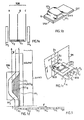
- FIG. 4b shows a perspective three-quarter view of a first embodiment TMI, of a transducer according to the invention, where the winding E 1 has four turns and the winding E 2 has seven turns.
- FIG. 5 is a block diagram of a second embodiment TMI 2 according to the invention comprising four windings E 1 , E 2 , E 3 , E 4 the winding E 1 being the winding closest to the part downstream polar while winding E4 is the most distant. Their respective number of turns is N 1 , N 2 , N 3 , N 4 with N 1 ⁇ N 2 ⁇ N 3 ⁇ N 4 .
- Winding E 1 and winding E 2 have a common electrical point F
- winding E 2 and winding E 3 have a common electrical point E
- winding E 3 and winding E4 have an electrical point common of.
- E ' 1 can be constituted by the winding E 1 traversed by the same current I 1 )
- E' 2 is then constituted by the association in series of the windings E 2 , E 3 , E4 (traversed by the same current I 2 ): in this case, the current generator is connected between the electrical point F and the end A of the winding BOB, the electrical points D 'and E not being connected to the generator.
- E “ 1 can be constituted by associating in series the windings E 1 and E 2 traversed by I 1 ), E" 2 then being constituted by the association in series of the windings E 3 and E 4 (traversed by 1 2 ): in in this case, the electrical points D 'and F are not connected to the current generator.
- the quantity ⁇ PP represents the magnetic flux of the windings E ' 1 and E' 2 , through the pole pieces PP 1 , while the quantity ⁇ "PP 1 represents the magnetic flux of the windings E" 1 and E " 2 through this same PP downstream pole piece.
- FIG. 6 shows the curve of variation of the magnetic induction in six elementary magnetic domains A 1 to A 6 successive of a track p of the magnetic disc SM. These domains are recorded by any of the TMI 1 , TMI 2 and TMI 3 transducers according to the invention.
- the module identical B 3 of positive inductions in domains A 1 , A 3 and A 5 is equal to the identical module B 4 of negative inductions in domains A 2 , A 4 and A 6 .
Landscapes
- Engineering & Computer Science (AREA)
- Manufacturing & Machinery (AREA)
- Magnetic Heads (AREA)
- Recording Or Reproducing By Magnetic Means (AREA)
Claims (2)

Applications Claiming Priority (2)
| Application Number | Priority Date | Filing Date | Title |
|---|---|---|---|
| FR7926532 | 1979-10-25 | ||
| FR7926532A FR2468183A1 (fr) | 1979-10-25 | 1979-10-25 | Transducteur magnetique integre |
Publications (2)
| Publication Number | Publication Date |
|---|---|
| EP0028177A1 EP0028177A1 (de) | 1981-05-06 |
| EP0028177B1 true EP0028177B1 (de) | 1984-07-18 |
Family
ID=9231044
Family Applications (1)
| Application Number | Title | Priority Date | Filing Date |
|---|---|---|---|
| EP80401422A Expired EP0028177B1 (de) | 1979-10-25 | 1980-10-06 | Integrierter Magnetwandler |
Country Status (5)
| Country | Link |
|---|---|
| US (1) | US4323941A (de) |
| EP (1) | EP0028177B1 (de) |
| JP (1) | JPS5683827A (de) |
| DE (1) | DE3068612D1 (de) |
| FR (1) | FR2468183A1 (de) |
Families Citing this family (8)
| Publication number | Priority date | Publication date | Assignee | Title |
|---|---|---|---|---|
| FR2549271B1 (fr) * | 1983-07-13 | 1989-05-26 | Cii Honeywell Bull | Transducteur magnetique hautement integre d'ecriture d'informations sur un support magnetique |
| NL8501144A (nl) * | 1985-04-19 | 1986-11-17 | Philips Nv | Magnetische overdrachtskop. |
| US4694368A (en) * | 1986-01-10 | 1987-09-15 | Read-Rite Corporation | Thin film magnetic head with three superimposed coils |
| US5063468A (en) * | 1990-05-08 | 1991-11-05 | North American Philips Corporation | Compatible magnetic head assembly |
| US6496330B1 (en) * | 1999-09-09 | 2002-12-17 | Read-Rite Corporation | Magnetic write head having a splitcoil structure |
| US6674610B1 (en) * | 2000-06-16 | 2004-01-06 | Western Digital (Fremont), Inc. | Thin film write head with universal coil design |
| US7006336B2 (en) * | 2002-08-06 | 2006-02-28 | International Business Machines Corporation | Magnetic head having a heater circuit for thermally-assisted writing |
| US7589936B1 (en) * | 2003-12-04 | 2009-09-15 | Seagate Technology Llc | Center-tapped write coil |
Family Cites Families (10)
| Publication number | Priority date | Publication date | Assignee | Title |
|---|---|---|---|---|
| DE877208C (de) * | 1951-04-20 | 1953-05-21 | Siemens Ag | Magnetkopf fuer Magnettongeraete |
| FR1070484A (fr) * | 1952-09-30 | 1954-07-27 | Electronique & Automatisme Sa | Perfectionnements aux enregistreurs de signaux sur support magnétique |
| FR1366446A (fr) * | 1963-08-16 | 1964-07-10 | Telefunken Patentverwertungese | Dispositif de tête magnétique |
| FR2209154B1 (de) * | 1972-07-03 | 1975-04-11 | Cii | |
| JPS51117020A (en) * | 1975-04-07 | 1976-10-14 | Hitachi Ltd | Magnetic head and production method of it |
| FR2315139A1 (fr) * | 1975-06-19 | 1977-01-14 | Cii | Nouvelle structure de tete magnetique integree |
| JPS5315120A (en) * | 1976-07-27 | 1978-02-10 | Mitsubishi Electric Corp | Magnetic head |
| JPS5319013A (en) * | 1976-08-05 | 1978-02-21 | Fujitsu Ltd | Writing circuit for magnetic memory apparatus |
| JPS5398811A (en) * | 1977-02-09 | 1978-08-29 | Hitachi Ltd | Thin film magnetic head |
| US4260450A (en) * | 1979-01-15 | 1981-04-07 | Magnex Corporation | Method of fabrication for thin film magnetic transducers |
-
1979
- 1979-10-25 FR FR7926532A patent/FR2468183A1/fr active Granted
-
1980
- 1980-06-09 US US06/157,845 patent/US4323941A/en not_active Expired - Lifetime
- 1980-10-06 EP EP80401422A patent/EP0028177B1/de not_active Expired
- 1980-10-06 DE DE8080401422T patent/DE3068612D1/de not_active Expired
- 1980-10-24 JP JP14824880A patent/JPS5683827A/ja active Pending
Also Published As
| Publication number | Publication date |
|---|---|
| US4323941A (en) | 1982-04-06 |
| FR2468183A1 (fr) | 1981-04-30 |
| DE3068612D1 (en) | 1984-08-23 |
| EP0028177A1 (de) | 1981-05-06 |
| JPS5683827A (en) | 1981-07-08 |
| FR2468183B1 (de) | 1984-06-01 |
Similar Documents
| Publication | Publication Date | Title |
|---|---|---|
| EP0340085B1 (de) | Magnetkopf-Matrixanordnung, insbesondere aus Dünnfilmen | |
| EP0107589B1 (de) | Vorrichtung zum Aufzeichnen von Informationen auf einem magnetischen Träger | |
| EP0337879A1 (de) | Vorrichtung zum Schreiben auf und Lesen von einem magnetischen Träger und Herstellungsverfahren | |
| FR2575577A1 (fr) | Transducteur magnetique d'ecriture/lecture pour enregistrement perpendiculaire | |
| EP0046697B1 (de) | Integrierter Magnetwandler | |
| EP0467737A1 (de) | Magnetische Wiedergabevorrichtung mit einem matrixartigen Netzwerk von Leseköpfen | |
| FR2645314A1 (fr) | Tete magnetique a magnetoresistance pour enregistrement longitudinal et procede de realisation d'une telle tete | |
| EP0028177B1 (de) | Integrierter Magnetwandler | |
| EP0467736A1 (de) | Magnetoresistiver Effekt verwendender Lesemagnetkopf | |
| EP0035943B1 (de) | Magnetkopf mit veränderbarer Spurbreite zum magnetischen Aufzeichnen oder Wiedergeben von Daten | |
| EP0061363B1 (de) | Magnetoresistiver Lesewandler für grosse Informationsdichtheit | |
| EP0392906B1 (de) | Statischer Lese-Magnetkopf | |
| EP0040994B1 (de) | Magnetwandler, der einen Spalt mit veränderbarer Grössen-Dimension aufweist, zur Wiedergabe oder zum Aufzeichnen von Informationen eines magnetischen Trägers | |
| EP0369839B1 (de) | Magnetischer Kopf mit sättigbarem Spalt und Matrixanordnung bestehend aus einem Satz mit solchen Köpfen | |
| FR2521377A1 (fr) | Appareil d'enregistrement et de lecture optique | |
| EP0041409A1 (de) | Magnetwandler zur Wiedergabe oder zum Aufzeichnen von Informationen eines magnetischen Trägers | |
| FR2774797A1 (fr) | Procede de realisation d'un ensemble a plusieurs tetes magnetiques et ensemble a tetes multiples obtenu par ce procede | |
| EP0188943B1 (de) | Schreib-Magnetwandler zur transversalen Aufzeichnung | |
| FR2494952A1 (fr) | Transducteur magnetoresistant de lecture d'un support d'enregistrement a haute densite d'informations | |
| EP0132186B1 (de) | Höchstintegrierter Magnetwandler zum Schreiben von Informationen auf einem magnetischen Träger | |
| EP0434547A1 (de) | Mehrspur-Lesemagnetkopf | |
| EP0409673B1 (de) | Integrierter Magnetaufzeichnungskopf | |
| EP0694909A1 (de) | Magnetkopf mit sättigbarem Element und Matrixanordnung bestehend aus einem Satz von Magnetköpfen | |
| FR2617629A1 (fr) | Memoire a ligne de bloch et procede pour transferer une ligne de bloch | |
| MAURICE | Towards the multitrack digital video tape recorder |
Legal Events
| Date | Code | Title | Description |
|---|---|---|---|
| PUAI | Public reference made under article 153(3) epc to a published international application that has entered the european phase |
Free format text: ORIGINAL CODE: 0009012 |
|
| AK | Designated contracting states |
Designated state(s): DE GB IT NL |
|
| 17P | Request for examination filed |
Effective date: 19810406 |
|
| ITF | It: translation for a ep patent filed | ||
| GRAA | (expected) grant |
Free format text: ORIGINAL CODE: 0009210 |
|
| AK | Designated contracting states |
Designated state(s): DE GB IT NL |
|
| REF | Corresponds to: |
Ref document number: 3068612 Country of ref document: DE Date of ref document: 19840823 |
|
| PG25 | Lapsed in a contracting state [announced via postgrant information from national office to epo] |
Ref country code: NL Effective date: 19850501 |
|
| PLBE | No opposition filed within time limit |
Free format text: ORIGINAL CODE: 0009261 |
|
| STAA | Information on the status of an ep patent application or granted ep patent |
Free format text: STATUS: NO OPPOSITION FILED WITHIN TIME LIMIT |
|
| GBPC | Gb: european patent ceased through non-payment of renewal fee | ||
| NLV4 | Nl: lapsed or anulled due to non-payment of the annual fee | ||
| PG25 | Lapsed in a contracting state [announced via postgrant information from national office to epo] |
Ref country code: DE Effective date: 19850702 |
|
| 26N | No opposition filed | ||
| PG25 | Lapsed in a contracting state [announced via postgrant information from national office to epo] |
Ref country code: GB Effective date: 19881118 |