EP0028285B1 - Dispositif de fixation d'une lame de scie circulaire à un tourillon d'entraînement - Google Patents
Dispositif de fixation d'une lame de scie circulaire à un tourillon d'entraînement Download PDFInfo
- Publication number
- EP0028285B1 EP0028285B1 EP80103797A EP80103797A EP0028285B1 EP 0028285 B1 EP0028285 B1 EP 0028285B1 EP 80103797 A EP80103797 A EP 80103797A EP 80103797 A EP80103797 A EP 80103797A EP 0028285 B1 EP0028285 B1 EP 0028285B1
- Authority
- EP
- European Patent Office
- Prior art keywords
- saw blade
- drive pin
- clamping
- means according
- clamping elements
- Prior art date
- Legal status (The legal status is an assumption and is not a legal conclusion. Google has not performed a legal analysis and makes no representation as to the accuracy of the status listed.)
- Expired
Links
- 230000008878 coupling Effects 0.000 claims description 8
- 238000010168 coupling process Methods 0.000 claims description 8
- 238000005859 coupling reaction Methods 0.000 claims description 8
- 230000004323 axial length Effects 0.000 claims description 5
- 238000007493 shaping process Methods 0.000 claims 2
- 210000002105 tongue Anatomy 0.000 description 6
- 238000011161 development Methods 0.000 description 1
- 230000018109 developmental process Effects 0.000 description 1
- 238000003780 insertion Methods 0.000 description 1
- 230000037431 insertion Effects 0.000 description 1
- 230000002093 peripheral effect Effects 0.000 description 1
- 238000004080 punching Methods 0.000 description 1
- 230000000284 resting effect Effects 0.000 description 1
Images


Classifications
-
- B—PERFORMING OPERATIONS; TRANSPORTING
- B27—WORKING OR PRESERVING WOOD OR SIMILAR MATERIAL; NAILING OR STAPLING MACHINES IN GENERAL
- B27B—SAWS FOR WOOD OR SIMILAR MATERIAL; COMPONENTS OR ACCESSORIES THEREFOR
- B27B5/00—Sawing machines working with circular or cylindrical saw blades; Components or equipment therefor
- B27B5/29—Details; Component parts; Accessories
- B27B5/30—Details; Component parts; Accessories for mounting or securing saw blades or saw spindles
- B27B5/32—Devices for securing circular saw blades to the saw spindle
-
- B—PERFORMING OPERATIONS; TRANSPORTING
- B23—MACHINE TOOLS; METAL-WORKING NOT OTHERWISE PROVIDED FOR
- B23D—PLANING; SLOTTING; SHEARING; BROACHING; SAWING; FILING; SCRAPING; LIKE OPERATIONS FOR WORKING METAL BY REMOVING MATERIAL, NOT OTHERWISE PROVIDED FOR
- B23D61/00—Tools for sawing machines or sawing devices; Clamping devices for these tools
- B23D61/02—Circular saw blades
- B23D61/10—Circular saw blades clamped between hubs; Clamping or aligning devices therefor
-
- Y—GENERAL TAGGING OF NEW TECHNOLOGICAL DEVELOPMENTS; GENERAL TAGGING OF CROSS-SECTIONAL TECHNOLOGIES SPANNING OVER SEVERAL SECTIONS OF THE IPC; TECHNICAL SUBJECTS COVERED BY FORMER USPC CROSS-REFERENCE ART COLLECTIONS [XRACs] AND DIGESTS
- Y10—TECHNICAL SUBJECTS COVERED BY FORMER USPC
- Y10T—TECHNICAL SUBJECTS COVERED BY FORMER US CLASSIFICATION
- Y10T83/00—Cutting
- Y10T83/869—Means to drive or to guide tool
- Y10T83/8719—With transmission yieldable on overload
-
- Y—GENERAL TAGGING OF NEW TECHNOLOGICAL DEVELOPMENTS; GENERAL TAGGING OF CROSS-SECTIONAL TECHNOLOGIES SPANNING OVER SEVERAL SECTIONS OF THE IPC; TECHNICAL SUBJECTS COVERED BY FORMER USPC CROSS-REFERENCE ART COLLECTIONS [XRACs] AND DIGESTS
- Y10—TECHNICAL SUBJECTS COVERED BY FORMER USPC
- Y10T—TECHNICAL SUBJECTS COVERED BY FORMER US CLASSIFICATION
- Y10T83/00—Cutting
- Y10T83/929—Tool or tool with support
- Y10T83/9372—Rotatable type
- Y10T83/9377—Mounting of tool about rod-type shaft
- Y10T83/9379—At end of shaft
-
- Y—GENERAL TAGGING OF NEW TECHNOLOGICAL DEVELOPMENTS; GENERAL TAGGING OF CROSS-SECTIONAL TECHNOLOGIES SPANNING OVER SEVERAL SECTIONS OF THE IPC; TECHNICAL SUBJECTS COVERED BY FORMER USPC CROSS-REFERENCE ART COLLECTIONS [XRACs] AND DIGESTS
- Y10—TECHNICAL SUBJECTS COVERED BY FORMER USPC
- Y10T—TECHNICAL SUBJECTS COVERED BY FORMER US CLASSIFICATION
- Y10T83/00—Cutting
- Y10T83/929—Tool or tool with support
- Y10T83/9457—Joint or connection
- Y10T83/9464—For rotary tool
Definitions
- the invention relates to a fastening device according to the preamble of the main claim.
- a symbol in the form of an arrow of rotation is generally attached to the saw blade, which is intended to prevent the saw blade from being reversed.
- the saw blade it happens again and again that the saw blade is incorrectly installed, because no constructional means are provided that actually prevent the saw blade from being reversed.
- the arrangement according to the invention with the characterizing features of the main claim has the advantage that an incorrect clamping of the saw blade is avoided with simple constructional means which do not influence the frictional engagement and thus the proper functioning of the friction clutch formed by the frictional engagement between the saw blade and the drive pin.
- the axial projection on the saw blade can be formed by a collar on the attachment opening of the saw blade, which engages in an enlarged bore section in one of the clamping elements.
- the axial projection is formed by at least one tongue which extends over the circumference of the one clamping element, the other clamping element having an annular cross-sectional profile, the outer radius of which is greater than the distance of the tongue from the axis of the drive pin.
- a normal saw blade can also be clamped onto the drive journal using the existing clamping elements, so that the fastening device can be used universally.
- the axial projection or a recess associated with the saw blade can advantageously be formed on a ring which is guided in the direction of rotation between the two clamping elements on the drive journal without positive engagement and with the saw blade over Coupling elements is rotatably connected, which at the same time prevent reverse assignment of the saw blade to the ring.
- the ring can advantageously carry the saw blade, whereby the coupling elements can advantageously be formed by a shape of the bore in the saw blade and of the peripheral portion of the ring that carries the saw blade and that deviates from the circular shape and is asymmetrical with respect to any radial plane that goes through the axis of rotation, so that additional attachments can be made There is no need for coupling pins or the like.
- the one clamping element has a collar which overlaps the fixed shoulder of the drive pin and whose inside diameter is smaller than the outside diameter is a thrust washer located under the head of the screw, and that the axial length of the collar is dimensioned such that if the saw blade is incorrectly fitted together with the two tensioning elements, the screw no longer engages in the threaded hole in the front end of the drive pin.
- Another way of avoiding the incorrect insertion of the saw blade together with the two tensioning elements is to design the seat of the drive pin for the tensioning element resting on its shoulder such that the other tensioning element cannot be pushed onto this seat.
- the arranged between the shoulder of the drive pin and the saw blade clamping element can also have other functions, for. B. with its face away from the saw blade as a stop for a ball bearing serve. If this clamping element is somehow held on the drive pin and does not easily come loose from the drive pin when the saw blade is replaced, the additional safeguard against incorrect attachment of the saw blade together with the two clamping elements can be dispensed with and only care must be taken that the saw blade does not stand alone can be inserted incorrectly.
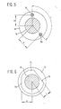
- FIG. 1 to 4 show the four exemplary embodiments, each enlarged and in section.
- FIG. 5 shows a section along the line V-V in FIG. 3 and in FIG. 6 a section along the line VI-VI in FIG. 4 is shown.
- a drive shaft 8 is provided with a pin 10 of smaller diameter, on which a saw blade is clamped with the aid of a thrust washer 12 and a screw 14 which is screwed into a threaded bore 16 in the front end of the pin 10.
- a thrust washer 12 is provided between the pin 10 and the drive shaft 8, an annular shoulder 18 is formed, against which the screw 14 presses the saw blade and two clamping elements arranged on its two sides, described in more detail below, the thrust washer 12 being supported on the head 20 of the screw 14.
- a saw blade 22 of wall thickness a is provided with an axial collar 24 at the circular plug-in opening, the end edge of which is removed by the dimension b from the opposite end face of the saw blade.
- a clamping ring 26 is arranged, which has an enlarged bore section 28 for receiving the collar 24 on the saw blade 22 and whose axial length measured in the area of the pin 10 is designated by c.
- the clamping ring 26 has an annular collar 30 on one side .
- the pin 10 has a chamfered round profile over its entire length f, to which the bore in the clamping ring 26 is adapted so that it is connected to the pin 10 in a rotationally fixed manner.
- a second clamping ring 34 On the other end face of the saw blade 22 there is a second clamping ring 34, the axial length of which is denoted by g, which is also non-rotatably coupled to the pin 10 and which protrudes a bit beyond its free end face.
- the thrust washer 12 On the clamping surface 36 of the clamping ring 34 facing away from the saw blade, there is the thrust washer 12, the outer diameter h of which is somewhat larger than the inner diameter e of the clamping ring 26 and the clamping surfaces on the clamping ring 34 and on the head 20 of the screw 14 are axially offset from one another by the dimension k are.
- the length of the threaded shaft of the screw 14 is denoted by 1.
- the clamped saw blade 22 is frictionally held between the two clamping rings 26 and 34 seated non-rotatably on the pin 10 and can rotate with respect to the pin 10 if the working torque exceeds a predetermined value determined by a controlled tightening torque of the screw 14.
- the thrust washer 12 is supported on the end face 32 of the clamping ring 26 because of its larger outer diameter h, so that there is between the head 20 of the screw 14 and the end face of the pin 10 a distance of the length a + d - f + k results, which is equal to or greater than the length I of the threaded pin of the screw 14, so that it can no longer be screwed into the internal thread of the pin 10.
- the clamping surface 36 of the clamping ring 34 stands back by the amount fbg from the end face of the pin 10, so that when tightening the Screw 14, the thrust washer 12 comes into contact with the end face of the pin 10 and the saw blade cannot be tightened, which in turn is immediately noticeable.
- a saw blade 40 has one or more axially projecting tongues 42 which are at a distance m from the axis of rotation 44 of the drive shaft 8.
- a clamping ring 46 is arranged between the saw blade 40 and the shoulder 18 at the beginning of the pin 10, the outer radius n of which is somewhat smaller than the distance m of the tongue 42 from the axis of rotation 44.
- On the other side of the saw blade 40 sits a second clamping ring 48 on the pin 10, the outer radius o of which is greater than the distance m.
- the pin 10 has a chamfered surface 49 and the bore of the clamping ring 48 is adapted to this cross-sectional profile of the pin 10 which deviates from the circular shape.
- the clamping ring 46 has a circular bore and can be pushed freely onto the pin 10 until it strikes the shoulder 18.
- the axial projections of the saw blades are formed by wall sections of the saw blades themselves.
- these axial projections are each formed on an additional ring which is connected in a rotationally fixed manner to the saw blade, 3 or that the saw blade is only to be provided with holes for the intended purpose, which can be done by punching.
- an additional ring 50 is provided, which is connected in a rotationally fixed manner to a saw blade 52 via two pins 54 and 56 (FIG. 5).
- the pins 54 and 56 have different distances p and q from the axis of rotation of the drive shaft 8 and are also offset from one another at an angle r which can have any value deviating from 180 degrees. Because of the different distances p and q to the axis of rotation and the angular offset r of the two pins 54 and 56 which deviates from 180 degrees, the saw blade 52 can only be attached to the ring 50 in the correct direction.
- the ring 50 and the saw blade 52 are frictionally clamped between two clamping rings 58 and 60, which themselves sit non-rotatably on the chamfered pin 10.
- the ring 50 has an axial collar 62 which engages over a circumferential section 64 of the clamping ring 58 which has a corresponding diameter.
- the collar 62 performs the same function as the collar 24 according to FIG. 1. Its axial length is such that the clamping ring 60 can no longer be fitted onto the pin 10 if the saw blade 52 together with the ring 50 is incorrectly seated on the pin 10.
- a safeguard against incorrect placement of the saw blade 52 together with all the rings 50, 58 and 60 is provided in the exemplary embodiment according to FIG.
- FIG. 4 differs from that of FIG. 3 in that between the two clamping rings 58 and 60 a support ring 70 is arranged, which is provided with a molded collar 72 on which a saw blade 74 is non-rotatably mounted.
- the collar 72 is provided with two chamfered surfaces 76 and 78, which have different distances a and t from the axis of rotation and are also not arranged parallel to one another.
- the support ring 70 itself, like the ring 50 in FIG. 3, is mounted on the pin 10 without a rotationally fixed connection.
- the different distances s and t as well as the non-parallelism ensure that the two chamfered surfaces 76 and 78 are not arranged in mirror image to one of the possible radial planes of the pin 10 that go through the axis of rotation.
- the bore in the saw blade 74 is adapted to the cross-sectional profile of the collar 72 of the support ring 70 provided with the two surfaces 76 and 78, thereby ensuring a non-rotatable and laterally correct assignment of the saw blade 74 to the support ring 70, forcing a connection between these two parts.
Landscapes
- Life Sciences & Earth Sciences (AREA)
- Engineering & Computer Science (AREA)
- Mechanical Engineering (AREA)
- Wood Science & Technology (AREA)
- Forests & Forestry (AREA)
- Sawing (AREA)
- Drilling Tools (AREA)
Claims (13)
Applications Claiming Priority (2)
| Application Number | Priority Date | Filing Date | Title |
|---|---|---|---|
| DE19792941358 DE2941358A1 (de) | 1979-10-12 | 1979-10-12 | Befestigungsvorrichtung fuer ein kreissaegeblatt auf einem antriebszapfen |
| DE2941358 | 1979-10-12 |
Publications (2)
| Publication Number | Publication Date |
|---|---|
| EP0028285A1 EP0028285A1 (fr) | 1981-05-13 |
| EP0028285B1 true EP0028285B1 (fr) | 1983-05-25 |
Family
ID=6083324
Family Applications (1)
| Application Number | Title | Priority Date | Filing Date |
|---|---|---|---|
| EP80103797A Expired EP0028285B1 (fr) | 1979-10-12 | 1980-07-16 | Dispositif de fixation d'une lame de scie circulaire à un tourillon d'entraînement |
Country Status (6)
| Country | Link |
|---|---|
| US (1) | US4343214A (fr) |
| EP (1) | EP0028285B1 (fr) |
| JP (1) | JPS5662716A (fr) |
| BR (1) | BR8005849A (fr) |
| DE (2) | DE2941358A1 (fr) |
| ES (4) | ES260961Y (fr) |
Families Citing this family (25)
| Publication number | Priority date | Publication date | Assignee | Title |
|---|---|---|---|---|
| JPS59100524U (ja) * | 1982-12-24 | 1984-07-06 | 株式会社日立工機原町 | 丸のこ切断機の切断刃物取り付け装置 |
| US4850109A (en) * | 1988-03-18 | 1989-07-25 | F. Gerald Mackin | Adaptor to convert a chain saw to a circular saw |
| US4959907A (en) * | 1988-10-27 | 1990-10-02 | Buratty John D | Circular saw accessory |
| AP250A (en) * | 1991-01-30 | 1993-03-17 | Advanced Mining Software Ltd | Saw blade drive. |
| US5303688A (en) * | 1992-04-03 | 1994-04-19 | Chiuminatta Edward R | Mounting arbor for saw cutting blades |
| US5366312A (en) * | 1993-08-18 | 1994-11-22 | Surgiquip, Inc. | Surgical saw blade attachment assembly |
| USD424076S (en) * | 1999-02-24 | 2000-05-02 | Black & Decker Inc. | Mounting device for a cutting tool |
| USD417598S (en) * | 1999-02-24 | 1999-12-14 | Black & Decker Inc. | Rotatable cutting tool |
| US6439091B1 (en) * | 1999-04-19 | 2002-08-27 | Black & Decker Inc. | Clutch mechanism |
| US7013987B2 (en) * | 2000-09-08 | 2006-03-21 | Black & Decker | Clutch assembly and clamp mechanism for rotary tool disc |
| US7866242B1 (en) * | 2002-04-19 | 2011-01-11 | Harris K Michael | Noise dampener hub assembly for a circular saw |
| FI116044B (fi) * | 2002-05-28 | 2005-09-15 | Metso Paper Inc | Paperi- tai kartonkirainan pituussuuntaisessa leikkauksessa käytettävä terä |
| US7137329B1 (en) | 2004-09-28 | 2006-11-21 | Moser Bruce A | Circular saw clutch assembly |
| US20060201302A1 (en) * | 2005-03-11 | 2006-09-14 | Schwaiger Barry M | Cutting tool and parts and accessories therefor |
| US8006596B2 (en) * | 2005-03-11 | 2011-08-30 | Walter Meier (Manufacturing) Inc. | Cutting tool and parts and accessories therefor |
| EP1733831A1 (fr) * | 2005-06-15 | 2006-12-20 | Georg Fischer Rohrverbindungstechnik GmbH | Lame de scie circulaire et dispositif de coupe de tubes à lame de scie circulaire |
| DE102007000252B4 (de) * | 2007-05-02 | 2022-02-17 | Hilti Aktiengesellschaft | Werkzeuggerät mit einer Abtriebswelle |
| USD619152S1 (en) | 2009-12-18 | 2010-07-06 | Techtronic Power Tools Technology Limited | Adapter |
| USD623034S1 (en) | 2009-12-18 | 2010-09-07 | Techtronic Power Tools Technology Limited | Tool arbor |
| JP5456556B2 (ja) | 2010-04-23 | 2014-04-02 | 株式会社マキタ | 作業工具 |
| USD653523S1 (en) | 2010-09-29 | 2012-02-07 | Milwaukee Electric Tool Corporation | Adapter for a tool |
| USD651062S1 (en) | 2010-09-29 | 2011-12-27 | Milwaukee Electric Tool Corporation | Tool interface for an accessory |
| USD646542S1 (en) | 2010-09-29 | 2011-10-11 | Milwaukee Electric Tool Corporation | Accessory interface for a tool |
| IL220671A (en) * | 2012-06-27 | 2013-06-27 | Shmuel Reznik | Material processing method and method |
| US9555554B2 (en) | 2013-05-06 | 2017-01-31 | Milwaukee Electric Tool Corporation | Oscillating multi-tool system |
Family Cites Families (12)
| Publication number | Priority date | Publication date | Assignee | Title |
|---|---|---|---|---|
| US335336A (en) * | 1886-02-02 | Edwin m | ||
| US51478A (en) * | 1865-12-12 | Improvement in centering circular saws | ||
| US1286799A (en) * | 1918-08-30 | 1918-12-03 | Otto Schuler | Device for hanging circular saws. |
| GB637521A (en) * | 1945-09-27 | 1950-05-24 | Earl Gustav Goehle | Improvements in or relating to rotary cutting tools |
| FR946884A (fr) * | 1947-05-17 | 1949-06-16 | Dispositif pour monter sur un même arbre plusieurs fraises-scies ou autres outils à des intervalles réglables | |
| GB624328A (en) * | 1947-07-03 | 1949-06-02 | Arthur Edward Smitten | Adaptor collars for machine spindles |
| FR966234A (fr) * | 1949-05-14 | 1950-10-04 | Manchon porte-outils pour machines à travailler le bois | |
| US2649868A (en) * | 1951-07-05 | 1953-08-25 | Borg Warner | Mounting rotors on arbors of various transaxial contours |
| DE959323C (de) * | 1955-07-05 | 1957-03-07 | Inh Dipl Ing Rudolf Mey | Kreissaegenblatt-Spannvorrichtung |
| US2854042A (en) * | 1956-06-11 | 1958-09-30 | Saw Engineering Inc | Mounting for circular saw blades |
| DE1728345B1 (de) * | 1962-06-12 | 1971-07-08 | Rolf Susemihl | Saegetisch fuer Mehrzweckkreissaegen |
| US4205572A (en) * | 1978-08-29 | 1980-06-03 | Weiner Robert I | Saw blade retainer and kickback clutch assembly |
-
1979
- 1979-10-12 DE DE19792941358 patent/DE2941358A1/de not_active Withdrawn
-
1980
- 1980-07-16 EP EP80103797A patent/EP0028285B1/fr not_active Expired
- 1980-07-16 DE DE8080103797T patent/DE3063491D1/de not_active Expired
- 1980-09-12 BR BR8005849A patent/BR8005849A/pt unknown
- 1980-09-19 US US06/188,597 patent/US4343214A/en not_active Expired - Lifetime
- 1980-10-10 ES ES1980260961U patent/ES260961Y/es not_active Expired
- 1980-10-13 JP JP14216080A patent/JPS5662716A/ja active Pending
-
1982
- 1982-01-19 ES ES1982262657U patent/ES262657Y/es not_active Expired
- 1982-01-19 ES ES1982262658U patent/ES262658Y/es not_active Expired
- 1982-01-19 ES ES1982262656U patent/ES262656Y/es not_active Expired
Also Published As
| Publication number | Publication date |
|---|---|
| ES262658Y (es) | 1983-01-16 |
| ES262657Y (es) | 1983-01-16 |
| ES260961U (es) | 1982-04-16 |
| ES260961Y (es) | 1982-11-16 |
| DE2941358A1 (de) | 1981-04-23 |
| ES262656Y (es) | 1983-01-16 |
| ES262656U (es) | 1982-07-01 |
| DE3063491D1 (en) | 1983-07-07 |
| ES262658U (es) | 1982-07-01 |
| EP0028285A1 (fr) | 1981-05-13 |
| ES262657U (es) | 1982-07-01 |
| JPS5662716A (en) | 1981-05-28 |
| US4343214A (en) | 1982-08-10 |
| BR8005849A (pt) | 1981-05-19 |
Similar Documents
| Publication | Publication Date | Title |
|---|---|---|
| EP0028285A1 (fr) | Dispositif de fixation d'une lame de scie circulaire à un tourillon d'entraînement | |
| EP2146813B1 (fr) | Adaptateur pour faire fonctionner une scie cloche sur une machine d'entraînement | |
| DE1525381B1 (de) | Elastische kupplung fuer zwei im wesentlichen gleichachsige wellen | |
| DE68910668T2 (de) | Kupplungsvorrichtung für Fluidleitungen. | |
| EP1945909B1 (fr) | Burin a tige circulaire comportant un porte-burin | |
| EP3472492B1 (fr) | Transmission à train épicycloïdal | |
| EP3077627A1 (fr) | Disque de roue pourvu d'une ou plusieurs plaques d'étanchéité | |
| EP0275441B1 (fr) | Dispositif de serrage | |
| DE2922186C2 (de) | Steckkupplung für mehrere Schlauchverbindungen | |
| EP0683931B1 (fr) | Appareil de commande et/ou de signalisation | |
| EP0717267A1 (fr) | Dispositif de montage pour un capteur | |
| DE3204677C2 (de) | Abstandsbüchse für die Befestigung eines Beschlagteils an einem Hohlprofil | |
| EP3387658B1 (fr) | Agencement d'aimant et aimant en plastique pour ledit agencement d'aimant | |
| DE69001870T2 (de) | Ventilflanschhaltesystem. | |
| EP0945211B1 (fr) | Adaptateur pour une connection non-rotative entre un outil et un dispositif d'entraínement en rotation agissant dans l'axe longitudinale de l'adaptateur | |
| DE4228946C2 (de) | Spindelkopf für Werkzeugrevolver | |
| DE2162090A1 (de) | Ausriickbare Mitnehmervorrichtung | |
| EP1281939A1 (fr) | Bague de fixation pour un compteur de liquide | |
| DE3131505C2 (fr) | ||
| DE1755669B2 (de) | Befestigungsvorrichtung fur Kraft fahrzeug Scheinwerfer | |
| DE2524373C2 (de) | Vorrichtung zum Kuppeln eines einem Rotationsverdampfer zugehörenden Dampfdurchführungsrohres mit einem angetriebenen Mitnehmerrohr | |
| DE3612800C2 (de) | Werkzeugaufnahme für Handwerkzeugmaschinen | |
| DE2028563C3 (de) | Ringflansch zum Befestigen einer zylindrischen Schleifscheibe großer Breite auf einer Spindel | |
| DE9103493U1 (de) | Flüssigkeitsreibungskupplung | |
| DE1525381C (de) | Elastische Kupplung für zwei im wesentlichen gleichachsige Wellen |
Legal Events
| Date | Code | Title | Description |
|---|---|---|---|
| PUAI | Public reference made under article 153(3) epc to a published international application that has entered the european phase |
Free format text: ORIGINAL CODE: 0009012 |
|
| 17P | Request for examination filed |
Effective date: 19800704 |
|
| AK | Designated contracting states |
Designated state(s): CH DE FR GB NL |
|
| GRAA | (expected) grant |
Free format text: ORIGINAL CODE: 0009210 |
|
| AK | Designated contracting states |
Designated state(s): CH DE FR GB LI NL |
|
| ET | Fr: translation filed | ||
| REF | Corresponds to: |
Ref document number: 3063491 Country of ref document: DE Date of ref document: 19830707 |
|
| PLBE | No opposition filed within time limit |
Free format text: ORIGINAL CODE: 0009261 |
|
| STAA | Information on the status of an ep patent application or granted ep patent |
Free format text: STATUS: NO OPPOSITION FILED WITHIN TIME LIMIT |
|
| 26N | No opposition filed | ||
| REG | Reference to a national code |
Ref country code: GB Ref legal event code: 746 |
|
| REG | Reference to a national code |
Ref country code: FR Ref legal event code: DL |
|
| PGFP | Annual fee paid to national office [announced via postgrant information from national office to epo] |
Ref country code: NL Payment date: 19940731 Year of fee payment: 15 |
|
| PGFP | Annual fee paid to national office [announced via postgrant information from national office to epo] |
Ref country code: GB Payment date: 19950619 Year of fee payment: 16 |
|
| PGFP | Annual fee paid to national office [announced via postgrant information from national office to epo] |
Ref country code: FR Payment date: 19950717 Year of fee payment: 16 |
|
| PGFP | Annual fee paid to national office [announced via postgrant information from national office to epo] |
Ref country code: CH Payment date: 19950719 Year of fee payment: 16 |
|
| PGFP | Annual fee paid to national office [announced via postgrant information from national office to epo] |
Ref country code: DE Payment date: 19950922 Year of fee payment: 16 |
|
| PG25 | Lapsed in a contracting state [announced via postgrant information from national office to epo] |
Ref country code: NL Effective date: 19960201 |
|
| NLV4 | Nl: lapsed or anulled due to non-payment of the annual fee |
Effective date: 19960201 |
|
| PG25 | Lapsed in a contracting state [announced via postgrant information from national office to epo] |
Ref country code: GB Effective date: 19960716 |
|
| PG25 | Lapsed in a contracting state [announced via postgrant information from national office to epo] |
Ref country code: LI Effective date: 19960731 Ref country code: CH Effective date: 19960731 |
|
| GBPC | Gb: european patent ceased through non-payment of renewal fee |
Effective date: 19960716 |
|
| REG | Reference to a national code |
Ref country code: CH Ref legal event code: PL |
|
| PG25 | Lapsed in a contracting state [announced via postgrant information from national office to epo] |
Ref country code: FR Effective date: 19970328 |
|
| PG25 | Lapsed in a contracting state [announced via postgrant information from national office to epo] |
Ref country code: DE Effective date: 19970402 |
|
| REG | Reference to a national code |
Ref country code: FR Ref legal event code: ST |