EP0028376B1 - Elektrische Lichtbogen-Kühlungsvorrichtung für die Kamine von Schaltgeräten - Google Patents
Elektrische Lichtbogen-Kühlungsvorrichtung für die Kamine von Schaltgeräten Download PDFInfo
- Publication number
- EP0028376B1 EP0028376B1 EP80106532A EP80106532A EP0028376B1 EP 0028376 B1 EP0028376 B1 EP 0028376B1 EP 80106532 A EP80106532 A EP 80106532A EP 80106532 A EP80106532 A EP 80106532A EP 0028376 B1 EP0028376 B1 EP 0028376B1
- Authority
- EP
- European Patent Office
- Prior art keywords
- cells
- cooling device
- electric arc
- section
- vents
- Prior art date
- Legal status (The legal status is an assumption and is not a legal conclusion. Google has not performed a legal analysis and makes no representation as to the accuracy of the status listed.)
- Expired
Links
- 238000001816 cooling Methods 0.000 title claims description 26
- 238000010891 electric arc Methods 0.000 title claims description 7
- 238000005192 partition Methods 0.000 claims description 8
- 229910010293 ceramic material Inorganic materials 0.000 claims 1
- 239000007789 gas Substances 0.000 description 3
- 239000011819 refractory material Substances 0.000 description 2
- 230000008033 biological extinction Effects 0.000 description 1
- 239000000919 ceramic Substances 0.000 description 1
- 230000007423 decrease Effects 0.000 description 1
- 230000006866 deterioration Effects 0.000 description 1
- 238000005553 drilling Methods 0.000 description 1
- 238000005516 engineering process Methods 0.000 description 1
- 239000011810 insulating material Substances 0.000 description 1
- 239000004033 plastic Substances 0.000 description 1
- 229920001169 thermoplastic Polymers 0.000 description 1
- 239000004416 thermosoftening plastic Substances 0.000 description 1
- 239000011800 void material Substances 0.000 description 1
Images

Classifications
-
- H—ELECTRICITY
- H01—ELECTRIC ELEMENTS
- H01H—ELECTRIC SWITCHES; RELAYS; SELECTORS; EMERGENCY PROTECTIVE DEVICES
- H01H33/00—High-tension or heavy-current switches with arc-extinguishing or arc-preventing means
- H01H33/02—Details
- H01H33/04—Means for extinguishing or preventing arc between current-carrying parts
- H01H33/08—Stationary parts for restricting or subdividing the arc, e.g. barrier plate
Definitions
- the present invention relates to an electric arc cooling device for chimneys of breaking devices such as circuit breakers or contractors used for high currents.
- the cooling device must be of good efficiency, that is to say that the gases leaving it must be at the lowest possible temperature in order to minimize the safety space that must always be provided in front of the chimney. .
- the blocks are made of a plastic, thermo-plastic insulating material or of refractory material.
- the cylindrical holes are relatively small in section and this results in a significant pressure drop in the plasma flow and moreover the contact surface between the gases and the insulating parts necessary for cooling is necessarily scaled down.
- the arc extinguishing chambers have thick added cell partitions which are secured by screws and whose dimensions are bulky. .
- the cooling device according to the present invention overcomes these drawbacks. In this one, in fact, the plasma flow is easy although its cooling is made more efficient and the size of the device is reduced to a minimum.
- the present invention relates to an electric arc cooling device for chimneys of breaking devices comprising at least one block, the section of which is crossed by cells, characterized in that the partitions separating said cells are of a thickness less than or equal to one fifth of one of the dimensions on the side of the section of one of said cells.
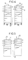
- FIG. 1 we see a cooling element 1 of refractory material such as ceramic consisting of cells 2 in the form of squares, separated by partitions 3 of very thin thickness, for example, 6/10 of a millimeter.
- the cells 2 have for example 34/10 of a millimeter on the side.
- the dimensions of the thickness of the partitions 3 are in a ratio of less than 0.2 with the dimensions of the side of the cell 2.
- the elements are able to withstand without deterioration the passage of the electric arc which is several thousand degrees centigrade and to absorb the major part of the heat energy of this arc. Due to the small thickness of the partitions 3 and the large section of the cells 2, the plasma flows without significant pressure drop. Indeed in our example for an element 1 of 12 x 50 square millimeters in cross section the total surface of the cells 2 is approximately 400 square millimeters.
- the cells 2 can be triangular (Figure 2) or hexagonal ( Figure 3) provided that the partitions 3 are thin and large void space; the cooling element 1 can be of rectangular or hexagonal section.
- the cooling devices of the invention installed in the chimney of a circuit breaker or a contactor that can operate at voltages of 3000 volts and currents of several thousand amperes make it possible to considerably reduce the size of these devices as well as the safety space at the front of the chimney.
- the applications are in the field of DC or AC circuit breakers which can be used in particular in railway technology.
Landscapes
- Arc-Extinguishing Devices That Are Switches (AREA)
- Vertical, Hearth, Or Arc Furnaces (AREA)
Claims (4)
Applications Claiming Priority (2)
| Application Number | Priority Date | Filing Date | Title |
|---|---|---|---|
| FR7927013 | 1979-10-31 | ||
| FR7927013A FR2468987A1 (fr) | 1979-10-31 | 1979-10-31 | Dispositif de refroidissement d'arc electrique pour cheminees d'appareils de coupure |
Publications (2)
| Publication Number | Publication Date |
|---|---|
| EP0028376A1 EP0028376A1 (de) | 1981-05-13 |
| EP0028376B1 true EP0028376B1 (de) | 1985-01-09 |
Family
ID=9231235
Family Applications (1)
| Application Number | Title | Priority Date | Filing Date |
|---|---|---|---|
| EP80106532A Expired EP0028376B1 (de) | 1979-10-31 | 1980-10-24 | Elektrische Lichtbogen-Kühlungsvorrichtung für die Kamine von Schaltgeräten |
Country Status (4)
| Country | Link |
|---|---|
| US (1) | US4414446A (de) |
| EP (1) | EP0028376B1 (de) |
| DE (1) | DE3069949D1 (de) |
| FR (1) | FR2468987A1 (de) |
Families Citing this family (1)
| Publication number | Priority date | Publication date | Assignee | Title |
|---|---|---|---|---|
| JP6676228B1 (ja) * | 2019-06-26 | 2020-04-08 | 三菱電機株式会社 | 気中遮断器 |
Family Cites Families (13)
| Publication number | Priority date | Publication date | Assignee | Title |
|---|---|---|---|---|
| FR961290A (de) * | 1950-05-09 | |||
| BE391540A (de) * | 1931-10-19 | |||
| US2362798A (en) * | 1942-06-30 | 1944-11-14 | Gen Electric | Electric switchgear |
| FR895927A (fr) * | 1943-04-08 | 1945-02-07 | Delle Atel Const Electr | Dispositif d'échappement des gaz pour disjoncteurs à auto-soufflage |
| GB568967A (en) * | 1943-11-05 | 1945-04-27 | David Reginald Davies | Improvements in and relating to gas blast electric switches or circuit breakers |
| BE480580A (de) * | 1946-07-29 | |||
| GB776748A (en) * | 1954-03-16 | 1957-06-12 | Reyrolle A & Co Ltd | Improvements relating to high-voltage air-break circuit-breakers |
| DE1064589B (de) * | 1955-11-10 | 1959-09-03 | Licentia Gmbh | Elektrischer Schalter mit Lichtbogenloeschkammer und mit magnetischer Blasung |
| CH337254A (de) * | 1955-11-30 | 1959-03-31 | Bbc Brown Boveri & Cie | Funkenkammeranordnung für Leistungsschalter |
| DE1040103B (de) * | 1957-03-20 | 1958-10-02 | Wissenschaftlich Tech Buero Fu | Loescheinsatz fuer elektrische Schaltgeraete |
| DE1291009B (de) * | 1963-06-01 | 1969-03-20 | Stotz Kontakt Gmbh | Installationsselbstschalter |
| FR1544434A (fr) * | 1966-11-14 | 1968-10-31 | Gen Electric | Disjoncteur électrique à boîte de soufflage de l'arc |
| US4019005A (en) * | 1974-12-30 | 1977-04-19 | I-T-E Imperial Corporation | Multi-pole circuit breaker with baffle shield venting |
-
1979
- 1979-10-31 FR FR7927013A patent/FR2468987A1/fr active Granted
-
1980
- 1980-10-24 EP EP80106532A patent/EP0028376B1/de not_active Expired
- 1980-10-24 DE DE8080106532T patent/DE3069949D1/de not_active Expired
- 1980-10-30 US US06/202,217 patent/US4414446A/en not_active Expired - Lifetime
Also Published As
| Publication number | Publication date |
|---|---|
| EP0028376A1 (de) | 1981-05-13 |
| FR2468987B1 (de) | 1982-05-21 |
| DE3069949D1 (en) | 1985-02-21 |
| US4414446A (en) | 1983-11-08 |
| FR2468987A1 (fr) | 1981-05-08 |
Similar Documents
| Publication | Publication Date | Title |
|---|---|---|
| EP2061051B1 (de) | Lichtbogenkammer und Schutzschalter, der mit einer solchen Lichtbogenkammer ausgestattet ist | |
| WO2023017220A1 (fr) | Contacteur double coupure bi-directionel | |
| EP3230997B1 (de) | Elektrische hochspannungsschutzschaltervorrichtung mit optimierter automatischer löschung | |
| EP0028376A1 (de) | Elektrische Lichtbogen-Kühlungsvorrichtung für die Kamine von Schaltgeräten | |
| FR2461349A1 (fr) | Chambre de coupure perfectionnee pour disjoncteur basse tension multipolaire a boitier moule | |
| FR3049387B1 (fr) | Dispositif de connexion de puissance electrique. | |
| EP0079293B1 (de) | Modulschalter mit magnetischem Blasfluss und mit Gaskühlung | |
| EP3035363B1 (de) | Lichtbogen-schaltkammer für einen leistungsschalter, und leistungsschalter, der eine solche kammer umfasst | |
| CA1162260A (fr) | Dispositif de securite contre les arcs electriques | |
| EP4341971B1 (de) | Elektrisches löschmodul mit einer magnetischen ausblasvorrichtung und elektrisches löschgerät mit einem solchen modul | |
| EP4631086A1 (de) | Elektrischer schütz mit integrierter schaltvorrichtung | |
| FR2784244A1 (fr) | Commutateur a eclateur a etages multiples | |
| EP1667180A1 (de) | Elektrische Schaltvorrichtung und Lichtbogenlöschkammer mit Deionisierungsflügeln | |
| FR2652198A1 (fr) | Dispositif interrupteur limiteur de courant. | |
| EP1842269A2 (de) | Einrichtung zum schutz elektrischer installationen mit verbesserter unterbrecherkapazität | |
| EP0660426A1 (de) | Strombegrenzer | |
| FR2511187A1 (fr) | Interrupteur electrique comprenant des toles d'extinction en un materiau conducteur de l'electricite et pouvant etre aimantees, dans lesquelles la face frontale presente au moins un evidement | |
| FR2484135A1 (fr) | Plage d'amenee de courant pour disjoncteur et procede de fabrication | |
| CH543170A (fr) | Interrupteur monopolaire à vide pour réseaux électriques de puissance | |
| EP0002406A1 (de) | Ionenquelle, insbesondere für eine Ionenimplantationseinrichtung | |
| EP4579713A1 (de) | Elektrische schutzvorrichtung mit gleichspannung durch sicherung | |
| FR2598556A1 (fr) | Dispositif de protection electrique autodestructeur | |
| FR2711012A1 (fr) | Disjoncteur à chambre d'extinction d'arc perfectionnée. | |
| EP1708332B1 (de) | Elektrische Schutzeinrichtung gegen transienten Überspannungen und entsprechende Schaltanlage | |
| FR3156236A1 (fr) | Appareillage de protection à coupure électronique avec dissipateur thermique |
Legal Events
| Date | Code | Title | Description |
|---|---|---|---|
| PUAI | Public reference made under article 153(3) epc to a published international application that has entered the european phase |
Free format text: ORIGINAL CODE: 0009012 |
|
| AK | Designated contracting states |
Designated state(s): CH DE FR GB IT NL |
|
| 17P | Request for examination filed |
Effective date: 19811026 |
|
| ITF | It: translation for a ep patent filed | ||
| GRAA | (expected) grant |
Free format text: ORIGINAL CODE: 0009210 |
|
| AK | Designated contracting states |
Designated state(s): CH DE FR GB IT LI NL |
|
| REF | Corresponds to: |
Ref document number: 3069949 Country of ref document: DE Date of ref document: 19850221 |
|
| PLBE | No opposition filed within time limit |
Free format text: ORIGINAL CODE: 0009261 |
|
| STAA | Information on the status of an ep patent application or granted ep patent |
Free format text: STATUS: NO OPPOSITION FILED WITHIN TIME LIMIT |
|
| 26N | No opposition filed | ||
| ITTA | It: last paid annual fee | ||
| PGFP | Annual fee paid to national office [announced via postgrant information from national office to epo] |
Ref country code: GB Payment date: 19960812 Year of fee payment: 17 |
|
| PGFP | Annual fee paid to national office [announced via postgrant information from national office to epo] |
Ref country code: DE Payment date: 19960814 Year of fee payment: 17 |
|
| PGFP | Annual fee paid to national office [announced via postgrant information from national office to epo] |
Ref country code: CH Payment date: 19960822 Year of fee payment: 17 |
|
| PGFP | Annual fee paid to national office [announced via postgrant information from national office to epo] |
Ref country code: FR Payment date: 19960912 Year of fee payment: 17 |
|
| PGFP | Annual fee paid to national office [announced via postgrant information from national office to epo] |
Ref country code: NL Payment date: 19961031 Year of fee payment: 17 |
|
| PG25 | Lapsed in a contracting state [announced via postgrant information from national office to epo] |
Ref country code: GB Free format text: LAPSE BECAUSE OF NON-PAYMENT OF DUE FEES Effective date: 19971024 |
|
| PG25 | Lapsed in a contracting state [announced via postgrant information from national office to epo] |
Ref country code: LI Free format text: LAPSE BECAUSE OF NON-PAYMENT OF DUE FEES Effective date: 19971031 Ref country code: FR Free format text: THE PATENT HAS BEEN ANNULLED BY A DECISION OF A NATIONAL AUTHORITY Effective date: 19971031 Ref country code: CH Free format text: LAPSE BECAUSE OF NON-PAYMENT OF DUE FEES Effective date: 19971031 |
|
| PG25 | Lapsed in a contracting state [announced via postgrant information from national office to epo] |
Ref country code: NL Free format text: LAPSE BECAUSE OF NON-PAYMENT OF DUE FEES Effective date: 19980501 |
|
| REG | Reference to a national code |
Ref country code: CH Ref legal event code: PL |
|
| GBPC | Gb: european patent ceased through non-payment of renewal fee |
Effective date: 19971024 |
|
| NLV4 | Nl: lapsed or anulled due to non-payment of the annual fee |
Effective date: 19980501 |
|
| PG25 | Lapsed in a contracting state [announced via postgrant information from national office to epo] |
Ref country code: DE Free format text: LAPSE BECAUSE OF NON-PAYMENT OF DUE FEES Effective date: 19980701 |
|
| REG | Reference to a national code |
Ref country code: FR Ref legal event code: ST |