EP0028396A2 - Endoskop - Google Patents
Endoskop Download PDFInfo
- Publication number
- EP0028396A2 EP0028396A2 EP80106649A EP80106649A EP0028396A2 EP 0028396 A2 EP0028396 A2 EP 0028396A2 EP 80106649 A EP80106649 A EP 80106649A EP 80106649 A EP80106649 A EP 80106649A EP 0028396 A2 EP0028396 A2 EP 0028396A2
- Authority
- EP
- European Patent Office
- Prior art keywords
- endoscope
- cap
- engagement
- peripheral wall
- cylindrical
- Prior art date
- Legal status (The legal status is an assumption and is not a legal conclusion. Google has not performed a legal analysis and makes no representation as to the accuracy of the status listed.)
- Granted
Links
Images

Classifications
-
- A—HUMAN NECESSITIES
- A61—MEDICAL OR VETERINARY SCIENCE; HYGIENE
- A61B—DIAGNOSIS; SURGERY; IDENTIFICATION
- A61B1/00—Instruments for performing medical examinations of the interior of cavities or tubes of the body by visual or photographical inspection, e.g. endoscopes; Illuminating arrangements therefor
- A61B1/00131—Accessories for endoscopes
- A61B1/00137—End pieces at either end of the endoscope, e.g. caps, seals or forceps plugs
-
- A—HUMAN NECESSITIES
- A61—MEDICAL OR VETERINARY SCIENCE; HYGIENE
- A61B—DIAGNOSIS; SURGERY; IDENTIFICATION
- A61B1/00—Instruments for performing medical examinations of the interior of cavities or tubes of the body by visual or photographical inspection, e.g. endoscopes; Illuminating arrangements therefor
- A61B1/00112—Connection or coupling means
- A61B1/00121—Connectors, fasteners and adapters, e.g. on the endoscope handle
- A61B1/00124—Connectors, fasteners and adapters, e.g. on the endoscope handle electrical, e.g. electrical plug-and-socket connection
-
- A—HUMAN NECESSITIES
- A61—MEDICAL OR VETERINARY SCIENCE; HYGIENE
- A61B—DIAGNOSIS; SURGERY; IDENTIFICATION
- A61B1/00—Instruments for performing medical examinations of the interior of cavities or tubes of the body by visual or photographical inspection, e.g. endoscopes; Illuminating arrangements therefor
- A61B1/12—Instruments for performing medical examinations of the interior of cavities or tubes of the body by visual or photographical inspection, e.g. endoscopes; Illuminating arrangements therefor with cooling or rinsing arrangements
- A61B1/121—Instruments for performing medical examinations of the interior of cavities or tubes of the body by visual or photographical inspection, e.g. endoscopes; Illuminating arrangements therefor with cooling or rinsing arrangements provided with means for cleaning post-use
-
- G—PHYSICS
- G01—MEASURING; TESTING
- G01M—TESTING STATIC OR DYNAMIC BALANCE OF MACHINES OR STRUCTURES; TESTING OF STRUCTURES OR APPARATUS, NOT OTHERWISE PROVIDED FOR
- G01M3/00—Investigating fluid-tightness of structures
- G01M3/02—Investigating fluid-tightness of structures by using fluid or vacuum
- G01M3/04—Investigating fluid-tightness of structures by using fluid or vacuum by detecting the presence of fluid at the leakage point
- G01M3/06—Investigating fluid-tightness of structures by using fluid or vacuum by detecting the presence of fluid at the leakage point by observing bubbles in a liquid pool
Definitions
- This invention relates to an endoscope which includes a tubular end portion such as a connector or an ocular section and provided at its end with an opening communicating with a closed space in the endoscope, and a fluid-proof cap which is mounted on the tubular end portion when the endoscope is washed and disinfected.
- An endoscope generally comprises an elongate insertion section including an observation optical fiber bundle and an illumination optical fiber bundle.
- the insertion section is put into the coeliac cavity of a human body (hereinafter simply referred to as "the coeliac cavity”) for observation or diagnosis.
- a process of examining the coeliac cavity by means of an endoscope has made a rapid progress in recent years. Since endoscopes naturally increase in number, it is demanded to establish a quick, easy, unfailing process of washing and disinfecting an endoscope.
- an endoscope manufactured to date can not be wholly dipped in a washing or disinfecting liquid due to its specific construction. Therefore, it has been necessary to wash and disinfect the respective sections of the endoscope with a great deal of time and work. Further difficulties have been experienced with respect to the prior art endoscope that when it is repeatedly applied, minute holes or cracks unobservable or unnoticeable to the operator take place in the insertion section, central section or any other part of an endoscope, undesirably resulting in the influx of a washing or disinfecting liquid into the endoscope through such defective parts.
- this invention provides an endoscope which comprises an internal space extending through the endoscope over its substantially whole length, at least one cylindrical end portion which is connected to the endoscope and provided with an air port only through which the internal space of the endoscope communicates with the open air, and a fluid-proof cap which has an inner peripheral wall is complementary to the outer peripheral wall of the cylindrical end portion, and which comprises an 0-ring disposed in the inner peripheral wall of the cap to seal between the outer peripheral wall of the cylindrical end portion and the inner peripheral wall of the cap, and fitting means for detachably mounting the cap on the cylindrical end portion, and one end of which is opened to allow for the insertion of said cylindrical end portion, and the other end of which is closed.
- the volume of the internal space of the cylindrical end portion becomes small, causing the air held in the space to be compressed.
- the compressed air is conducted into the internal space of the endoscope body through the air port of the cylindrical end portion, thereby elevating air pressure prevailing in said internal space. Even if, therefore, fine holes or cracks are produced in the endoscope body, its cylindrical end portion, etc. a washing or disinfecting solution is prevented from flowing into the endoscope through such defective parts.
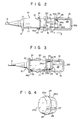
- an endoscope embodying this invention comprises a control housing 1, an ocular section 2 fixed to a proximal end of the control housing 1, an elongate flexible sheath 3 extending from a distal end of the control housing 1, a bend section 4 fixed to the distal end of the sheath 3, and a distal end section 5 fixed to the distal end of the bend section 4.
- An operation knob 6 is mounted on one lateral wall of the control housing 1.
- the bend section 4 can be flexed with an optional radius of curvature in any desired direction by means of operation wires (not shown) which extend through the control housing 1, sheath 3 and bend section 4 and whose ends are respectively connected to the operation knob 6 and the proximal end of the distal end section 5.
- An assembly of the control housing 1, sheath 3, bend section 4 and distal end section 5 is hereinafter referred to as "an endoscope body 7".
- An objective (not shown) is set in the distal end section 5.
- An image guide (not shown) formed of optical fiber bundles extends through the endoscope body 7. The distal end of the image guide is optically connected to the objective, and the proximal end of the image guide is optically connected to an ocular (not shown).
- a light guide 8 formed of an optical fiber bundle extends through the endoscope body 7 from the distal end of the distal end section 5 (in the case of a front view type endoscope) and from the lateral wall of the distal end section 5 (in the case of a side view type endoscope). The light guide 8 further extends through a flexible umbilical cord 9 from one lateral wall of the control housing 1.
- a connector 10 which is to be fitted into a receptacle (not shown) of a light source device is fixed to the free end of the umbilical cord 9.
- the connector 10 comprises a cylindrical body 11 whose rear end is provided with a circular flange 12.
- a cylindrical insertion section 13 is projectively provided at the forward end of the cylindrical body 11.
- An annular engagement ridge 14 is formed at the forward end.
- a light guide tube 15 protrudes from the forward end of the cylindrical insertion section 13.
- the light guide 8 reaches the free end of the light guide tube 15.
- the receptacle of the light source device (not shown) has a shape complementary to the outer peripheral wall of the insertion section 13.
- the cylindrical insertion section 13 is closely fitted into the receptacle.
- the annular engagement ridge 14 is inserted into an annular groove (not shown) formed in the light source receptacle.
- the connector 10 is securely supported in the light source receptacle. Light beams emitted from a light source are conducted to the end of the light guide tube 15.
- the above-mentioned endoscope has the same construction as the known type.
- the endoscope body 7 of this invention are provided with the known endoscope parts. However, description is omitted of the parts which fail outside of the scope and object of this invention.
- An endoscope comprises cylindrical end portions, such as the proximal end of the ocular section 2 and the free end (forward end) of the connector 10 which should be protected by being covered in a fluid-proof state when the endoscope is wholly washed or disinfected.
- the cylindrical end portion requiring the above-mentioned protection is taken to be the connector 10.
- the free end (forward end) of the connector 10 is provided with an air port 16 through which the internal space 17 of the umbilical cord 9 communicates with the outside of the connector 10.
- the internal space 17 of the umbilical cord 9 communicates with a closed internal space 18 formed in the endoscope body 7 (Fig. 1).
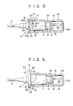
- a hollow cylindrical fluid-proof cap 19 is prepared from a material such as stainless steel which is not corroded by water and chemicals. One end 19a of the cap 19 is opened, and the other end 19b thereof is closed.
- the inner peripheral wall 20 of the cap 19 has a diameter substantially equal to the outer diameter of the cylindrical body 11 of the connector 10.
- An annular groove 21 is formed in that portion of the inner peripheral wall 20 which lies near said one end 19a.
- An 0-ring 22 prepared from an elastic material such as rubber is fitted into the annular groove 21.
- annular projection or annular ridge 23 Formed in the intermediate part of the inner peripheral wall 20 of the cap 19 is an annular projection or annular ridge 23 which has a right angled triangular cross section and whose truncated conical inner face 23a is directed toward the closed end 19b of the cap 19.
- the cap 19 contains an annular fixing member 24.
- This fixing member 24 comprises a truncated conical abutting section 25 whose outer peripheral wall 25a is complementary to the inclined plane 23a of the annular projection 23, and a truncated engagement section 26 whose outer peripheral wall 26a projects from the large diameter end of the abutting section 25 and is inclined in the opposite direction to that in which the outer peripheral wall 25a is inclined.
- the fixing member 24 is set in the cap 19 with the outer peripheral wall 25a pressed against the inclined plane 23a of the annular projection 23.
- the inner peripheral wall 24a of the fixing member 24 defines a truncated conical form whose inner diameter progressively decreases as measured from the abutting section 25 toward the engagement section 26.
- An axially extending notch 27 is formed in the fixing member 24.
- This fixing member 24 is prepared from an elastic material such as polytetrafluoroethylene. The fixing member 24 is inserted into the cap 19 at its open end 19a. When the fixing member 24 rides over the annular projection 23, the outer diameter of the fixing member 24 is reduced due to the presence of the notch 27. When carried beyond the annular projection 23, the fixing member 24 has its outer diameter returned to the original measurement, and occupies a prescribed position.
- Air in the air chamber 28 of the cap 19 is more compressed as the cap 19 is further pushed in the direction of the arrow A.
- the compressed air passes through the air port 16, the internal space 17 of the umbilical cord 9 and the internal space 18 of the endoscope body 7 to elevate air pressure prevailing in the internal spaces 17, 18 to a higher level than that of the open air. In this case, it is assumed that the internal spaces 17, 18 do not communicate with the open air except through the air port 16.
- the above-mentioned arrangement prevents a liquid from being carried into the internal spaces 17, 18 from the outside.
- the proximal end of the ocular section 2 is enclosed in a cover, the endoscope can be wholly washed and disinfected by water and a chemical solution.
- the fluid-proof cap 19 further has the merit of enabling the operator to recognize the presence of fine holes or cracks in the endoscope device from the emission of air bubbles through the defective parts, thereby eliminating the necessity of taking any other particular means for inspection of the condition of the endoscope device.
- the fluid-proof cap can be used as a protective cover for the cylindrical end portions of the endoscope device when it is not used for the inspection of the coeliac cavity of the human body.
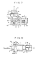
- the connector 10 of the second embodiment of Fig. 5 is different from that of the first embodiment of Fig. 1 in the following respects.
- That portion of the cylindrical body 11 which lies adjacent to the circular flange 12 constitutes a cylindrical larger diameter section 29.
- Equidistantly arranged in the larger diameter section 29 in the circumferential direction are L-shaped grooves 30 each consisting of an axial groove portion 30a axially extending from the insertion section 13 of the cylindrical body 11 and circumferential groove portion 30b circumferentially extending and formed contiguously to the axially groove portion 30a.
- That portion of the fluid-proof cap 19 which lies adjacent to the open end 19a thereof constitutes an engagement section 32 whose larger diameter inner peripheral wall 31 has the same inner diameter as the outer diameter of the cylindrical larger diameter section 29.
- Projectively provided on the engagement section 32 are a plurality of engagement pins 33 in the same number as engagement grooves 30. The inner ends of the pins 33 are aligned with the inner peripheral wall 20 of the cap 19, and further face the circumferential groove portions 30b of the engagement grooves 30.
- the fluid-proof cap fixing means of the third embodiment has a mechanism 101.
- a pair of blind holes or engagement block chambers 34 (preferably square holes) are provided which extend inward from the outer periphery of the circular flange 12 of the connector 10 and diametrically face each other.
- Engaged with the blind holes 34 are engagement blocks 35 whose outer peripheral wall has a complementary shape to that of the blind holes 34.
- a parallelepiped hole 36 open to the distal end side of the connector 10 is provided nearer to the axis of the connector 10 as measured from the intermediate part of the engagement block 35.
- Pawls 37 project from that end of a base portion 35a defining the innermost walls of the horizontal parallelepiped holes 36 which face the distal end of the connector 10 toward the outermost wall of the holes 36, that is, radially toward the outside of the connector 10.
- the engagement block 35 is always radially urged toward the outside of the connector 10 by a compression coil spring 38 which is provided in the blind hole 34, and the respective ends of which are respectively pressed against the inner wall of the engagement block 35 and the bottom wall of the blind hole 34.
- the inner peripheral wall 19c of the open end 19a of the cap 19 has a larger diameter than the inner peripheral wall 20 of the cap 19.
- Pawls 39 extend axially from the open end 19a of the cap 19 so as to be engageable with the pawls 37 of the engagement block 35.
- An elongate slot 40 whose cross section extends radially of the connector 10 is formed in that portion of the engagement block 35 which is positioned nearer to the outer portion of the block 35 as measured from the hole 36. Inserted into the slot 40 is a set pin 41 axially penetrating the flange 12. The head 41a of the pin 41 is engaged with the flange 12. The opposite end of the pin 41 to its head 41a is provided with a screw 41b. A nut 42 is threadedly engaged with the screw 41b to fix the pin 41 to this flange 12.
- the radial width i of the slot 40 and the position taken by the set pin 41 relative to the slot 40 are so determined as to bring about the conditions, in which, when not depressed, the engagement block 35 is radially moved by the spring 38 toward the outside of the connector 10, causing the pawls 37, 39 to engage each other; and when the engagement block 35 is depressed in the direction of an arrow B, the pawl 37 is fully disengaged from the pawl 39.
- the operator depresses the engagement blocks 35 by his fingers in the direction of the arrow; the cap 19 is rendered ready to be released from th f connector 10. When the operator's fingers are taken ff the engagement blocks 35, the cap 19 is automatically fixed to the connector 10.
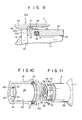
- This fourth embodiment comprises the undermentioned mechanism 102 for fixing fluid-proof cap 19.
- Radially outwardly extending projections 43 are provided in that outer peripheral portion of the cap 19 which lies near its open end 19a.
- Engagement members 44 are each shaped substantially like a triangle as viewed from the lateral side.
- An axial U-shaped groove 45 is formed in the engagement' member 44 in a state extending from the substantially central part to one end of the engagement member 44.
- the other end of the engagement member 44 is provided with a pawl 46.
- Each of the engagement members 44 are positioned such that said end of engagement member 44 is directed toward the closed end 19b of the cap 19, whereby the U-shaped projections 43 can be inserted into the corresponding U-shaped grooves 45.
- the central portion of the engagement member 44 is pivoted to the respective projection 43 by a shaft 47.
- the shaft 47 is wounded by a tension spring 48.
- the both arms of the tension spring 48 push the outer wall of the cap 19 and the inner face of the engagement member 44 so that the engagement is elastically urged counterclockwise in Fig. 9 to allow the pawl 46 to move toward the axis of the cap 19.
- Fig. 9 eliminates the necessity of providing the connector 10 with some elements of the fixing member 102, simplifying the construction of the connector 10, and offering the advantage of preventing the original function of the connector 10 from being otherwise obstructed by the attachment of said elements of the fixing member 102.
- the cylindrical end portion of the endoscope is the ocular section 2.
- This ocular section 2 is generally fitted with a photographing camera and other attachments.
- the end face 49 of the ocular section 2 is provided with openings or air ports (indicated, for example, by reference numerals 50, 51) for communication with the internal space 18 of the endoscope body 7 (Fig. 1). These openings have to be sealed before the endoscope is washed or disinfected.
- the ocular section 2 comprises a larger diameter cylindrical base portion 52 and a smaller diameter distal end section 53 provided with an ocular diopter-adjusting ring 54.
- the end face 49 constitutes that of said smaller diameter distal end section 53.
- Mounted on the end face 49 of the smaller diameter distal end section 53 is an engagement section 55 formed of a ring portion 56 having the same outer diameter as that of the outer peripheral wall of the distal end section 53 and an inwardly extending flange 57.
- a plurality of notches 58 are formed in the inner edge of the flange 57 in a state diametrically facing each other or equidistantly arranged in the circumferential direction.
- the fluid-proof cap 19 is a hollow cylindrical member, one end 19a of which is opened, and the other end 19b of which is closed, and is prepared from the same material as that which is used in the other embodiments.
- the inner peripheral wall 20 of the cap 19 has a diameter substantially the same as the_ outer diameter of the cylindrical base portion 52 of the ocular section 2.
- An air chamber 28 is defined by the inner peripheral wall 20 of the cap 19 and the inner wall of the closed end 19b thereof.
- An annular groove 21 is formed in that portion of the inner peripheral wall 20 of the cap 19 which is disposed adjacent to the open end 19a thereof.
- An O-ring 22 prepared from an elastic material such as rubber is fitted into the annular groove 21.
- the engagement section 59 is provided in the closed end 19b.
- the engagement section 59 comprises a ring portion 60 having an outer diameter substantially the same as the diameter of the inner edge of the flange 57 of the engagement section 55 of the ocular section 2 and a pair of or a plurality of pawls 61 which are formed on the peripheral wall of that part of the ring portion 60 which is nearer to the open end 19a of the cap 19 for insertion into the notches 58 of the ocular section 2.
- the pawls 61 diametrically face each other or are equidistantly arranged in the circumferential direction of the ring portion 60.
- the 0-ring 22 is pressed against the outer peripheral wall of the base portion 52, thereby sealing the ocular section 2.
- air in the air chamber 28 of the cap 19 is progressively compressed as in the other embodiments.
- the compressed air flows into the internal space 18 of the endoscope body 7 (Fig. 1) to compress air held therein, thus ensuring the fluid-proof effect.
- the presence of fine holes or cracks in the endoscope body can be determined in the same manner as described in connection with the first embodiment.
- both engagement sections 55, 59 jointly constitute the fluid-proof cap fixing means.
Landscapes
- Health & Medical Sciences (AREA)
- Life Sciences & Earth Sciences (AREA)
- Surgery (AREA)
- Physics & Mathematics (AREA)
- Biomedical Technology (AREA)
- Molecular Biology (AREA)
- Pathology (AREA)
- Radiology & Medical Imaging (AREA)
- Nuclear Medicine, Radiotherapy & Molecular Imaging (AREA)
- Engineering & Computer Science (AREA)
- Biophysics (AREA)
- Heart & Thoracic Surgery (AREA)
- Medical Informatics (AREA)
- Optics & Photonics (AREA)
- Animal Behavior & Ethology (AREA)
- General Health & Medical Sciences (AREA)
- Public Health (AREA)
- Veterinary Medicine (AREA)
- General Physics & Mathematics (AREA)
- Endoscopes (AREA)
- Eye Examination Apparatus (AREA)
Priority Applications (1)
| Application Number | Priority Date | Filing Date | Title |
|---|---|---|---|
| AT80106649T ATE6983T1 (de) | 1979-10-31 | 1980-10-29 | Endoskop. |
Applications Claiming Priority (2)
| Application Number | Priority Date | Filing Date | Title |
|---|---|---|---|
| JP140647/79 | 1979-10-31 | ||
| JP54140647A JPS5939128B2 (ja) | 1979-10-31 | 1979-10-31 | 内視鏡 |
Publications (3)
| Publication Number | Publication Date |
|---|---|
| EP0028396A2 true EP0028396A2 (de) | 1981-05-13 |
| EP0028396A3 EP0028396A3 (en) | 1981-07-22 |
| EP0028396B1 EP0028396B1 (de) | 1984-04-11 |
Family
ID=15273516
Family Applications (1)
| Application Number | Title | Priority Date | Filing Date |
|---|---|---|---|
| EP80106649A Expired EP0028396B1 (de) | 1979-10-31 | 1980-10-29 | Endoskop |
Country Status (5)
| Country | Link |
|---|---|
| US (1) | US4404963A (de) |
| EP (1) | EP0028396B1 (de) |
| JP (1) | JPS5939128B2 (de) |
| AT (1) | ATE6983T1 (de) |
| DE (1) | DE3067465D1 (de) |
Cited By (5)
| Publication number | Priority date | Publication date | Assignee | Title |
|---|---|---|---|---|
| EP0089823A3 (en) * | 1982-03-19 | 1984-02-29 | Olympus Optical Co., Ltd. | Leakage detector of endoscopes |
| EP0100069A3 (en) * | 1982-07-27 | 1984-09-05 | Olympus Optical Co., Ltd. | Connector device for checking leakage in an airtight endoscope |
| EP0100977A3 (en) * | 1982-08-09 | 1984-11-07 | Olympus Optical Co., Ltd. | Endoscope |
| US10441142B2 (en) | 2013-07-22 | 2019-10-15 | Digital Endoscopy Gmbh | Sealing component for an endoscope connector |
| US10441152B2 (en) | 2014-01-24 | 2019-10-15 | Digital Endoscopy Gmbh | Tracking the fundamental frequency of a voice signal in real time |
Families Citing this family (23)
| Publication number | Priority date | Publication date | Assignee | Title |
|---|---|---|---|---|
| JPH0112804Y2 (de) * | 1984-09-05 | 1989-04-14 | ||
| JPH0365615U (de) * | 1989-10-30 | 1991-06-26 | ||
| US5863286A (en) * | 1993-01-27 | 1999-01-26 | Olympus Optical Company, Ltd. | Endoscope system including endoscope and disposable protection cover |
| US5630787A (en) * | 1993-02-18 | 1997-05-20 | Olympus Optical Co., Ltd. | System including endoscope and disposable protection cover with channel |
| US5674182A (en) * | 1993-02-26 | 1997-10-07 | Olympus Optical Co., Ltd. | Endoscope system including endoscope and protection cover |
| US5554098A (en) * | 1993-02-26 | 1996-09-10 | Olympus Optical Co., Ltd. | Endoscope system including endoscope and disposable protection cover |
| US5674180A (en) * | 1993-03-15 | 1997-10-07 | Olympus Optical Co., Ltd. | Endoscope system including endoscope and disposable protection cover |
| US5551945A (en) * | 1993-03-16 | 1996-09-03 | Olympus Optical Co., Ltd. | Endoscope system including endoscope and protection cover |
| US5695447A (en) * | 1993-03-16 | 1997-12-09 | Olympus Optical Company, Ltd. | Endoscope system including endoscope and disposable protection cover |
| US5630783A (en) * | 1995-08-11 | 1997-05-20 | Steinberg; Jeffrey | Portable cystoscope |
| US6401066B1 (en) * | 1999-11-09 | 2002-06-04 | West Teleservices Holding Company | Automated third party verification system |
| US6491625B1 (en) | 2000-03-27 | 2002-12-10 | The Scope Exchange, Inc. | Endoscopy testing apparatus and method |
| JP3821206B2 (ja) * | 2000-09-29 | 2006-09-13 | フジノン株式会社 | 内視鏡のコネクタ用防水キャップ |
| ES2322750B1 (es) * | 2009-02-10 | 2010-07-15 | Francisco Santi Soriano Romero | Dispositivo para el control de fugas de un endoscopio. |
| DE102013222041A1 (de) | 2013-10-30 | 2015-04-30 | Digital Endoscopy Gmbh | Auslenkbewegungsübertragungseinrichtung, Endoskopdeflectingsteuerung und Endoskop |
| DE102013222042A1 (de) | 2013-10-30 | 2015-04-30 | Digital Endoscopy Gmbh | Auslenkbewegungsübertragungseinrichtung, Endoskopdeflectingsteuerung und Endoskop |
| DE102013222039A1 (de) | 2013-10-30 | 2015-04-30 | Digital Endoscopy Gmbh | An ein Mutterendoskop anbringbares Sekundärendoskop und Kombination aus Mutterendoskop und Sekundärendoskop |
| DE102013224683A1 (de) | 2013-12-02 | 2015-06-03 | Digital Endoscopy Gmbh | Endoskopkopf und endoskop |
| DE102013226591A1 (de) | 2013-12-19 | 2015-06-25 | Digital Endoscopy Gmbh | Vorrichtung und verfahren zum herstellen eines länglichen hohlprofilelements, längliches hohlprofilelement und eine abwinkelungseinheit für ein endoskop |
| DE102014201208A1 (de) | 2014-01-23 | 2015-07-23 | Digital Endoscopy Gmbh | Fluidblock für ein endoskopbedienteil und endoskop |
| JP6121084B1 (ja) * | 2015-06-29 | 2017-04-26 | オリンパス株式会社 | 内視鏡 |
| DE102015113016B4 (de) | 2015-08-07 | 2018-03-29 | Digital Endoscopy Gmbh | Endoskopkopf |
| CN111493796B (zh) * | 2020-05-22 | 2025-01-10 | 上海臻察科技有限公司 | 一种一体化内窥镜导光连接器及导光连接器锁紧装置 |
Family Cites Families (13)
| Publication number | Priority date | Publication date | Assignee | Title |
|---|---|---|---|---|
| US1880551A (en) * | 1929-10-05 | 1932-10-04 | Reinhold H Wappler | Endoscope |
| US2449920A (en) * | 1946-03-07 | 1948-09-21 | Diversified Designing & Machin | Conduit coupling |
| GB801784A (en) * | 1955-09-05 | 1958-09-24 | Automotive Prod Co Ltd | Improvements in or relating to closure devices for fluid supply connections and the like |
| FR1241277A (fr) * | 1959-08-06 | 1960-09-16 | Lorraine Des Procedes Bauer So | Raccord à joint flottant |
| US3503637A (en) * | 1967-06-15 | 1970-03-31 | Sosaburo Maeshiba | Pipe coupling with spring biased detents |
| GB1334339A (en) * | 1972-05-01 | 1973-10-17 | Mueller Co | Joint for smooth end or flareless pipe |
| US3821970A (en) * | 1972-07-24 | 1974-07-02 | Gen Connector Corp | Quick disconnect cap for conduits |
| JPS5436470Y2 (de) * | 1974-01-11 | 1979-11-02 | ||
| JPS5722883Y2 (de) * | 1977-02-21 | 1982-05-18 | ||
| JPS6121041Y2 (de) * | 1977-08-04 | 1986-06-24 | ||
| JPS5457039U (de) * | 1977-09-28 | 1979-04-20 | ||
| FR2415451A1 (fr) * | 1978-01-26 | 1979-08-24 | Bernard Parent | Hysteroscope de diagnostic a vision panoramique |
| JPS5545468A (en) * | 1978-09-29 | 1980-03-31 | Olympus Optical Co | Connector for endoscope |
-
1979
- 1979-10-31 JP JP54140647A patent/JPS5939128B2/ja not_active Expired
-
1980
- 1980-10-23 US US06/199,866 patent/US4404963A/en not_active Expired - Lifetime
- 1980-10-29 DE DE8080106649T patent/DE3067465D1/de not_active Expired
- 1980-10-29 AT AT80106649T patent/ATE6983T1/de active
- 1980-10-29 EP EP80106649A patent/EP0028396B1/de not_active Expired
Cited By (5)
| Publication number | Priority date | Publication date | Assignee | Title |
|---|---|---|---|---|
| EP0089823A3 (en) * | 1982-03-19 | 1984-02-29 | Olympus Optical Co., Ltd. | Leakage detector of endoscopes |
| EP0100069A3 (en) * | 1982-07-27 | 1984-09-05 | Olympus Optical Co., Ltd. | Connector device for checking leakage in an airtight endoscope |
| EP0100977A3 (en) * | 1982-08-09 | 1984-11-07 | Olympus Optical Co., Ltd. | Endoscope |
| US10441142B2 (en) | 2013-07-22 | 2019-10-15 | Digital Endoscopy Gmbh | Sealing component for an endoscope connector |
| US10441152B2 (en) | 2014-01-24 | 2019-10-15 | Digital Endoscopy Gmbh | Tracking the fundamental frequency of a voice signal in real time |
Also Published As
| Publication number | Publication date |
|---|---|
| EP0028396B1 (de) | 1984-04-11 |
| EP0028396A3 (en) | 1981-07-22 |
| JPS5663328A (en) | 1981-05-29 |
| US4404963A (en) | 1983-09-20 |
| DE3067465D1 (en) | 1984-05-17 |
| ATE6983T1 (de) | 1984-04-15 |
| JPS5939128B2 (ja) | 1984-09-21 |
Similar Documents
| Publication | Publication Date | Title |
|---|---|---|
| EP0028396B1 (de) | Endoskop | |
| CN111741706B (zh) | 具有分离型探头的内窥镜 | |
| JP3739592B2 (ja) | 腹腔鏡装置 | |
| US3261349A (en) | Endoscope | |
| US4414608A (en) | Endoscope with adapter | |
| US4534339A (en) | Endoscope | |
| US5702347A (en) | Endoscope system including endoscope and disposable protection cover | |
| EP0082950A2 (de) | Flüssigkeitszuführungs-Vorrichtung für ein Endoskop | |
| JPH044567B2 (de) | ||
| US4569334A (en) | Apparatus for restoring the light transmittance of an image-transmitting optical fiber bundle used in a fiber optic endoscope | |
| JP4276995B2 (ja) | 内視鏡用滅菌テストパック | |
| CN111511261A (zh) | 插入设备 | |
| EP0081098A2 (de) | Endoskop | |
| US4770443A (en) | Inserted part of an industrial endoscope | |
| US6277068B1 (en) | Laryngoscope and lamp cartridge assembly | |
| JP4129312B2 (ja) | 内視鏡装置 | |
| EP2574272B1 (de) | Endoskopzangenstecker | |
| JP2016202192A (ja) | 硬性内視鏡 | |
| JPWO2013125114A1 (ja) | 内視鏡 | |
| US5124838A (en) | Optical coupler | |
| JP2008029742A (ja) | 内視鏡 | |
| JP6600093B2 (ja) | 内視鏡用光学アダプタ着脱補助具及び内視鏡システム | |
| JP3903737B2 (ja) | 内視鏡の挿入部 | |
| JPWO2015050101A1 (ja) | 内視鏡 | |
| JP2828296B2 (ja) | 内視鏡 |
Legal Events
| Date | Code | Title | Description |
|---|---|---|---|
| PUAI | Public reference made under article 153(3) epc to a published international application that has entered the european phase |
Free format text: ORIGINAL CODE: 0009012 |
|
| AK | Designated contracting states |
Designated state(s): AT BE DE FR GB IT NL SE |
|
| PUAL | Search report despatched |
Free format text: ORIGINAL CODE: 0009013 |
|
| AK | Designated contracting states |
Designated state(s): AT BE DE FR GB IT NL SE |
|
| 17P | Request for examination filed |
Effective date: 19810727 |
|
| GRAA | (expected) grant |
Free format text: ORIGINAL CODE: 0009210 |
|
| AK | Designated contracting states |
Designated state(s): AT BE DE FR GB IT NL SE |
|
| PG25 | Lapsed in a contracting state [announced via postgrant information from national office to epo] |
Ref country code: SE Effective date: 19840411 Ref country code: NL Effective date: 19840411 Ref country code: IT Free format text: LAPSE BECAUSE OF FAILURE TO SUBMIT A TRANSLATION OF THE DESCRIPTION OR TO PAY THE FEE WITHIN THE PRESCRIBED TIME-LIMIT;WARNING: LAPSES OF ITALIAN PATENTS WITH EFFECTIVE DATE BEFORE 2007 MAY HAVE OCCURRED AT ANY TIME BEFORE 2007. THE CORRECT EFFECTIVE DATE MAY BE DIFFERENT FROM THE ONE RECORDED. Effective date: 19840411 Ref country code: BE Effective date: 19840411 Ref country code: AT Effective date: 19840411 |
|
| REF | Corresponds to: |
Ref document number: 6983 Country of ref document: AT Date of ref document: 19840415 Kind code of ref document: T |
|
| REF | Corresponds to: |
Ref document number: 3067465 Country of ref document: DE Date of ref document: 19840517 |
|
| ET | Fr: translation filed | ||
| NLV1 | Nl: lapsed or annulled due to failure to fulfill the requirements of art. 29p and 29m of the patents act | ||
| PLBE | No opposition filed within time limit |
Free format text: ORIGINAL CODE: 0009261 |
|
| STAA | Information on the status of an ep patent application or granted ep patent |
Free format text: STATUS: NO OPPOSITION FILED WITHIN TIME LIMIT |
|
| 26N | No opposition filed | ||
| PGFP | Annual fee paid to national office [announced via postgrant information from national office to epo] |
Ref country code: FR Payment date: 19891023 Year of fee payment: 10 |
|
| PGFP | Annual fee paid to national office [announced via postgrant information from national office to epo] |
Ref country code: GB Payment date: 19891031 Year of fee payment: 10 |
|
| PGFP | Annual fee paid to national office [announced via postgrant information from national office to epo] |
Ref country code: DE Payment date: 19891229 Year of fee payment: 10 |
|
| PG25 | Lapsed in a contracting state [announced via postgrant information from national office to epo] |
Ref country code: GB Effective date: 19901029 |
|
| GBPC | Gb: european patent ceased through non-payment of renewal fee | ||
| PG25 | Lapsed in a contracting state [announced via postgrant information from national office to epo] |
Ref country code: FR Effective date: 19910628 |
|
| PG25 | Lapsed in a contracting state [announced via postgrant information from national office to epo] |
Ref country code: DE Effective date: 19910702 |
|
| REG | Reference to a national code |
Ref country code: FR Ref legal event code: ST |