EP0028492A1 - Appareil pour la production de fibres de verre selon le procédé de fusion directe - Google Patents
Appareil pour la production de fibres de verre selon le procédé de fusion directe Download PDFInfo
- Publication number
- EP0028492A1 EP0028492A1 EP80303820A EP80303820A EP0028492A1 EP 0028492 A1 EP0028492 A1 EP 0028492A1 EP 80303820 A EP80303820 A EP 80303820A EP 80303820 A EP80303820 A EP 80303820A EP 0028492 A1 EP0028492 A1 EP 0028492A1
- Authority
- EP
- European Patent Office
- Prior art keywords
- forehearth
- bushing
- glass
- longitudinal direction
- strands
- Prior art date
- Legal status (The legal status is an assumption and is not a legal conclusion. Google has not performed a legal analysis and makes no representation as to the accuracy of the status listed.)
- Withdrawn
Links
Images

Classifications
-
- C—CHEMISTRY; METALLURGY
- C03—GLASS; MINERAL OR SLAG WOOL
- C03B—MANUFACTURE, SHAPING, OR SUPPLEMENTARY PROCESSES
- C03B7/00—Distributors for the molten glass; Means for taking-off charges of molten glass; Producing the gob, e.g. controlling the gob shape, weight or delivery tact
- C03B7/02—Forehearths, i.e. feeder channels
-
- C—CHEMISTRY; METALLURGY
- C03—GLASS; MINERAL OR SLAG WOOL
- C03B—MANUFACTURE, SHAPING, OR SUPPLEMENTARY PROCESSES
- C03B37/00—Manufacture or treatment of flakes, fibres, or filaments from softened glass, minerals, or slags
- C03B37/08—Bushings, e.g. construction, bushing reinforcement means; Spinnerettes; Nozzles; Nozzle plates
Definitions
- the present invention relates to an improvement of an apparatus for producing glass fibers by direct melt process in which one or more forehearths are communicated through a molten glass distribution channel with a glass melting and refining furnace; a plurality of bushings each provided with an orifice plate, which has a large number of orifices and is disposed at the bottom of the bushing, are arrayed in row in each forehearth; and glass filaments are drawn through the orifices of the orifice plate of the bushing into one or more strands which in turn are wound into one or more packages by a winder disposed under each bushing.
- the apparatus of the type described has been well known in the art and disclosed in for example United States Patent No. 3,406,021 and No. 3,561,939.
- the forehearth which is U-shaped in cross section, is constructed with high-quality heat insulating refractories and the molten glass is caused to flow through the forehearth in the longitudinal direction thereof in such a way that the flow rate'and the liquid level of the molten glass are maintained constant over the whole length of the forehearth.
- a plurality of auxiliary heating means such as burners are mounted on the side walls of the forehearth and spaced apart by a suitable distance from each other in the longitudinal direction.
- the transverse temperature distribution of the molten glass flowing through the forehearth is such that the temperature is highest at the center line of the forehearth, gradually drops toward the side walls and is lowest at the side walls.
- the bushings are so arranged that the longer sides of each rectangular bushing are in parallel with the longitudinal direction of the forehearth while the shorter sides are at right angles to the longitudinal direction, whereby a mass of the molten glass which is centered around the center line of the forehearth and has a small temperature distribution or gradient as possible flows into each bushing as will be described in detail below.
- a drawing and winding room is arranged to extend in parallel with and below the forehearth for the sake of facilitating the drawing and winding operations.
- this room one winder is disposed below each bushing in such a way that the axis of rotation of the spindle of the winder is perpendicular to the longitudinal direction of the forehearth, whereby the operators can face one ends of the spindles of the winders. Therefore the glass filaments are drawn into one or more strands which in turn are wound by the winder whose axis of rotation is perpendicular to the lengthwise direction of the bushing.
- a sizing application roller and a gathering roller must be disposed in parallel with the lengthwise direction of the bushing in order that the wrapping or contact angle of the glass filaments with respect to the rollers can be made as small as possible, whereby the overall tension exerting on the glass filaments can be reduced and the individual glass filaments are exerted with a uniform tension.
- the glass filaments drawn from one bushing are divided into a plurality of strands, they should be divided in the lengthwise direction of the bushing in view of the operational convenience.
- a guide shoe In order to wind the strand or strands thus formed by the winder whose axis of rotation is perpendicular to the lengthwise direction of the bushing as described previously a guide shoe must be provided, whereby the strands are redirected through 90° before they are wound by the winder. Because of this 90° turn, the qualities of the strands are degraded to some extent.
- the present invention was made therefore to overcome the above and other problems encountered in the prior art direct melt process type glass fiber production apapratus.
- the present invention provides an apparatus for producing glass fibers by direct melt process comprising; a glass melting and refining furnace; at least one elongate forehearth communicated with said glass melting and refining furnace through a molten glass distribution channel and filled with molten glass flowing in the longitudinal direction thereof; a plurality of bushings arrayed in one row extending in the longitudinal direction of said forehearth and opened at their tops to the bottom of said forehearth, each said bushing being rectangular in cross section and disposed in such a way that the shorter sides thereof are in parallel with the longitudinal direction of said forehearth and having at its bottom an orifice plate with a large number of orifices; a pair of electric resistance heating terminals attached to said bushing at the centers of the shorter sides thereof, respectively; a plurality of gathering rollers, each being disposed below each said bushing with its axis extending perpendicularly to the longitudinal direction of said forehearth for gathering a large number of glass
- a prior art apparatus for producing glass fibers will be briefly described with reference to Fig. 1.
- the glass is melted by a glass melting and refining furnace 1 and the melted glass is distributed through a distribution channel 2 into forehearth 3.
- the melted glass flows into each rectangular bushing 4 extending in the longitudinal direction of the forehearth 3 and is drawn into filaments through orifices of an orifice plate disposed at the bottom of the bushing 4.
- the forehearth 3 is provided on its side walls with a plurality of auxiliary heating means such as burners 5 so that the uniform temperature distribution of the melted glass can be maintained in the longitudinal direction.
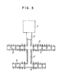
- the glass fiber production apparatus in accordance with the present invention is substantially similar in construction to the prior art apparatus described with. reference to Fig. 1 except that while in the prior apparatus the longer sides of each bushing 4 are in parallel with the longitudinal axis of the forehearth 3, the shorter sides of each bushing 4' are in parallel with the longitudinal axis of the forehearth 3'.
- the glass is melted in a glass melting and refining furnace 1' and the melted glass flows into the forehearths 3' through a distribution channel 2'.
- the melted glass flows into each bushing 4' and is drawn through orifices of the orifice plate at the bottom of the bushing 4' into a large number of filaments.
- a plurality of auxiliary heating means such as burners 5' are also provided.
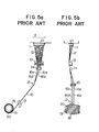
- Figs. 5a and 5b showing front and side views, respectively, of the prior art apparatus in which the longer sides of each bushing 4 are in parallel with the longitudinal axis of the forehearth 3, the axis of a spindle 19 of a winding machine is disposed perpendicular to the longitudinal axis F of the forehearth 3.
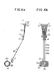
- the axis of rotation of the spindle 19 of the winding machine is also disposed perpendicular to the longitudinal axis F of the forehearth 3' in the glass fiber production apparatus in accordance with the present invention in which the shorter sides of each bushing are in parallel with the longitudinal axis F of the forehearth 3' as shown in front view in Fig. 6a and in side view in Fig. 6b.
- reference numeral 10 denotes a bushing of the forehearth 3 or 3'; 11, an orifice plate at the bottom of the bushing 10; 12, glass filaments drawn through orifices of the orifice plate 11; 13, a sizing applicator; 14, a gathering roller 16, a strand; 17, a traverse motion; 18, the strand wound around a bobbin 20 on the winding spindle 19 of the winding machine; and 15, a guide shoe which is used only in the prior art apparatus as shown in Fig. 5.
- the glass filaments 12 are applied with size by the sizing applicator 13 and then drawn into four separate strands 16a, 16b, l6c and 16d by gathering roller 14 which strands are traversed by the traverse motion 17 while being maintained in parallel relationship with each other and wound around the bobbin 20 on the spindle 19 to form a package.
- the guide shoe 15 can be eliminated if the axis of the gathering roller 14 is disposed in parallel with the axis of the spindle 19. In such case, however, the wrapping angles of the individual filaments 12 on the gathering roller 14 become different so that the tensions of the individual filaments are also different. As a result, high quality strand packages cannot be obtained.
- the use of the guide shoe 15 can be completely eliminated as shown in Fig. 6 so that undesired additional contacts with the guide shoe 15 of the filaments 12, which are weak in bending and friction, can be avoided.
- the filaments 12 and the strands 16 can be maintained at the uniform tension so that the strands 16 can be wound into uniform packages. As a result, no problem will arise when the packages are unwound.
- extremely high quality packages can be produced regardless of whether all the filments 12 are drawn into a single strand which in turn is wound into a single package, or the filaments 12 are drawn into a plurality of strands which in turn are maintained in parallel with each other and wound into a single package or into a plurality of packages on the single bobbin.
- the molten glass filled in the bushing can be maintained at the completely uniform temperature in the longitudinal direction of the bushing.
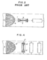
- the molten glass has such a temperature distribution that the temperature is highest at the center line and gradually drops toward the sides and is lowest at the sides. Therefore in the prior art glass fiber production apparatus, the longer sides of each busing 4 are in parallel with the longitudinal axis of the forehearth 3 so that the molten glass with as small a temperature difference range as possible flows into the bushing 4 and consequently the temperature distribution of the glass in the bushing can be maintained as uniform as possible.
- Fig. 2 showing the prior art arrangement of the bushing
- the temperature distribution of the glass in the forehearth 3 which is highest at the center line, gradually drops toward the sides of the forehearth and is lowest at the sides is shown at A. Therefore a mass of glass with the narrow temperature range a flows into the bushing 4.
- the temperature drop of the molten glass in the longitudinal direction of the forehearth 3 is prevented by the auxiliary heating means such as burners 5 as described elsewhere. Therefore, the uniform temperature distribution of the molten glass can be maintained lengthwise in the bushing 4, but the temperature distribution is not uniform widthwise.
- the terminals T are attached to the shorter sides of the bushing so that the molten glass is heated by Joule heat.
- the temperature distribution by Joule heat is varied depending upon the area of the heating surface of the terminal T.
- the terminals T have a large heating area, the temperature becomes higher at the shorter sides as shown at B in Fig. 2 and the smaller the area of the heating surfaces, the lower the temperature becomes at the shorter sides.
- the uniform temperature distribution cannot be attained even by the best adjustment of the heating surfaces with the temperature distribution A.
- the temperature distribution of the molten glass filled within the bushing 4' is maintained uniform in the direction of the shorter sides thereof or in the longitudinal direction of the forehearth 3' because of not only the shorter length of the bushing in this direction but also additional heating by the auxiliary heating means such as burners 5' provided on the side walls of the forehearth 3'.
- the temperature distribution in the direction of the longer sides of the bushing 4' or in the transverse direction of the forehearth 3' has a variation by far greater than that in the bushing 4 in the prior art arrangement as shown in Fig. 2, because, as shown in Fig.
- the bushing 4' is filled with a mass of molten glass within a temperature range a' in the transverse temperature distribution A' of the molten glass flowing through the forehearth 3', which range a' is very large as compared with the range a in Fig. 2.
- This greater temperature variation can be compensated by means of terminals T' attached to the centers of the shorter sides of the bushing 4'. which produce another temperature distribution as shown at B' in which the temperature is highest along the shroter sides and gradually drops toward the center of the bushing 4'. That is, the concave temperature distribution curve B' cancels the convext temperature distribution curve A' so that the resulting temperature distribution in the transverse direction becomes uniform.
- the temperature distribution of the molten glass in the bushing can be made more uniform by merely changing the direction of the bushing in the prior art glass fiber production apparatus through 90°.
- the spacing between the adjacent bushings can be reduced so that the number of bushings arranged in the forehearth can be increased.
- the glass fiber drawing operations can be much stabilized and the high productivity can be ensured.
- the strand winding step can be simplified and high-quality strands of glass fibers can be obtained.
- the uniform lengthwise and widthwise temperature distributions can be ensured in the bushings.
Landscapes
- Chemical & Material Sciences (AREA)
- Engineering & Computer Science (AREA)
- Materials Engineering (AREA)
- Organic Chemistry (AREA)
- Life Sciences & Earth Sciences (AREA)
- General Life Sciences & Earth Sciences (AREA)
- Geochemistry & Mineralogy (AREA)
- Manufacturing & Machinery (AREA)
- Manufacture, Treatment Of Glass Fibers (AREA)
Applications Claiming Priority (2)
| Application Number | Priority Date | Filing Date | Title |
|---|---|---|---|
| JP14081679A JPS5669237A (en) | 1979-10-31 | 1979-10-31 | Preparation apparatus of glass fiber |
| JP140816/79 | 1979-10-31 |
Publications (1)
| Publication Number | Publication Date |
|---|---|
| EP0028492A1 true EP0028492A1 (fr) | 1981-05-13 |
Family
ID=15277392
Family Applications (1)
| Application Number | Title | Priority Date | Filing Date |
|---|---|---|---|
| EP80303820A Withdrawn EP0028492A1 (fr) | 1979-10-31 | 1980-10-28 | Appareil pour la production de fibres de verre selon le procédé de fusion directe |
Country Status (4)
| Country | Link |
|---|---|
| EP (1) | EP0028492A1 (fr) |
| JP (1) | JPS5669237A (fr) |
| AU (1) | AU6355380A (fr) |
| BE (1) | BE885935A (fr) |
Cited By (1)
| Publication number | Priority date | Publication date | Assignee | Title |
|---|---|---|---|---|
| EP1806326A1 (fr) * | 2006-01-10 | 2007-07-11 | Johns Manville | Procédé de fibrage de verre fondu |
Citations (5)
| Publication number | Priority date | Publication date | Assignee | Title |
|---|---|---|---|---|
| US3561939A (en) * | 1967-11-22 | 1971-02-09 | Owens Corning Fiberglass Corp | Apparatus for processing filament-forming mineral materials and forming and packaging filaments |
| US3820967A (en) * | 1970-12-30 | 1974-06-28 | Johns Manville | Filament production monitor |
| FR2211407A1 (en) * | 1972-12-22 | 1974-07-19 | Johns Manville | Glass fibre drawing appts - with heat exchanger to control the local temp of the jets |
| US4146375A (en) * | 1972-09-20 | 1979-03-27 | Reichhold Chemicals, Inc. | Method for the continuous production of glass fiber strand |
| US4149865A (en) * | 1977-12-30 | 1979-04-17 | Nitto Boseki Co., Ltd. | Apparatus and method for the drawing of glass fiber |
-
1979
- 1979-10-31 JP JP14081679A patent/JPS5669237A/ja active Pending
-
1980
- 1980-10-21 AU AU63553/80A patent/AU6355380A/en not_active Abandoned
- 1980-10-28 EP EP80303820A patent/EP0028492A1/fr not_active Withdrawn
- 1980-10-30 BE BE0/202639A patent/BE885935A/fr unknown
Patent Citations (5)
| Publication number | Priority date | Publication date | Assignee | Title |
|---|---|---|---|---|
| US3561939A (en) * | 1967-11-22 | 1971-02-09 | Owens Corning Fiberglass Corp | Apparatus for processing filament-forming mineral materials and forming and packaging filaments |
| US3820967A (en) * | 1970-12-30 | 1974-06-28 | Johns Manville | Filament production monitor |
| US4146375A (en) * | 1972-09-20 | 1979-03-27 | Reichhold Chemicals, Inc. | Method for the continuous production of glass fiber strand |
| FR2211407A1 (en) * | 1972-12-22 | 1974-07-19 | Johns Manville | Glass fibre drawing appts - with heat exchanger to control the local temp of the jets |
| US4149865A (en) * | 1977-12-30 | 1979-04-17 | Nitto Boseki Co., Ltd. | Apparatus and method for the drawing of glass fiber |
Cited By (1)
| Publication number | Priority date | Publication date | Assignee | Title |
|---|---|---|---|---|
| EP1806326A1 (fr) * | 2006-01-10 | 2007-07-11 | Johns Manville | Procédé de fibrage de verre fondu |
Also Published As
| Publication number | Publication date |
|---|---|
| AU6355380A (en) | 1981-08-20 |
| BE885935A (fr) | 1981-02-16 |
| JPS5669237A (en) | 1981-06-10 |
Similar Documents
| Publication | Publication Date | Title |
|---|---|---|
| US3867119A (en) | Apparatus for manufacturing glass fibers | |
| US2963739A (en) | Method of applying metal to glas filaments and apparatus therefor | |
| US2772518A (en) | Method of coating glass filaments with metal | |
| US4328015A (en) | Process for the manufacture of fibers | |
| US2291289A (en) | Apparatus for making siliceous fibers | |
| US4612027A (en) | Method and apparatus for forming glass fibers | |
| US3328144A (en) | Apparatus for melting and processing heat-softenable mineral materials | |
| JP7111342B2 (ja) | ガラス繊維紡糸用ノズルプレート、当該ガラス繊維紡糸用ノズルプレートを有するガラス溶融炉、及び当該ガラス溶融炉を用いたガラス繊維紡糸方法 | |
| WO1984003882A1 (fr) | Procede et appareil pour former des fibres de verre | |
| US4436541A (en) | Method for production of mineral fibers | |
| US4398933A (en) | Method and apparatus for the manufacture of fibers | |
| US3512948A (en) | Apparatus for processing heat-softened mineral material | |
| RU2276209C2 (ru) | Способ и устройство для получения композитной нити | |
| US4437869A (en) | Method and apparatus for multifilament glass strand | |
| US4322041A (en) | Method of and apparatus for winding roving packages | |
| US3019078A (en) | Method of forming fibers | |
| US2377772A (en) | Apparatus for the production of glass fibers | |
| US5002598A (en) | Process of making multifilament glass strand | |
| US3254978A (en) | Method and apparatus for forming fibers | |
| CA1279192C (fr) | Raccord pour filiere chauffee de fabrication de la fibre de verre | |
| US3475147A (en) | Method and apparatus for processing heat-softened material | |
| US2861393A (en) | Production of coated-glass fibers | |
| US3266692A (en) | Tow stacking assembly | |
| US3821543A (en) | Apparatus for handling linear elements | |
| CA1115525A (fr) | Methode et dispositif pour le traitement de matieres thermofusibles formatrices de fibres |
Legal Events
| Date | Code | Title | Description |
|---|---|---|---|
| PUAI | Public reference made under article 153(3) epc to a published international application that has entered the european phase |
Free format text: ORIGINAL CODE: 0009012 |
|
| AK | Designated contracting states |
Designated state(s): DE FR GB IT NL |
|
| 17P | Request for examination filed |
Effective date: 19811005 |
|
| STAA | Information on the status of an ep patent application or granted ep patent |
Free format text: STATUS: THE APPLICATION IS DEEMED TO BE WITHDRAWN |
|
| 18D | Application deemed to be withdrawn |
Effective date: 19830425 |
|
| RIN1 | Information on inventor provided before grant (corrected) |
Inventor name: MINEZAKI, HISAO Inventor name: NAKAZAWA, KOJI Inventor name: FUJITA, TOSHIHITO |