EP0028566A2 - Mit Meerwasser aktivierte Zelle - Google Patents
Mit Meerwasser aktivierte Zelle Download PDFInfo
- Publication number
- EP0028566A2 EP0028566A2 EP80401545A EP80401545A EP0028566A2 EP 0028566 A2 EP0028566 A2 EP 0028566A2 EP 80401545 A EP80401545 A EP 80401545A EP 80401545 A EP80401545 A EP 80401545A EP 0028566 A2 EP0028566 A2 EP 0028566A2
- Authority
- EP
- European Patent Office
- Prior art keywords
- tubes
- tube
- elements
- stack
- network
- Prior art date
- Legal status (The legal status is an assumption and is not a legal conclusion. Google has not performed a legal analysis and makes no representation as to the accuracy of the status listed.)
- Granted
Links
Images

Classifications
-
- H—ELECTRICITY
- H01—ELECTRIC ELEMENTS
- H01M—PROCESSES OR MEANS, e.g. BATTERIES, FOR THE DIRECT CONVERSION OF CHEMICAL ENERGY INTO ELECTRICAL ENERGY
- H01M6/00—Primary cells; Manufacture thereof
- H01M6/30—Deferred-action cells
- H01M6/32—Deferred-action cells activated through external addition of electrolyte or of electrolyte components
- H01M6/34—Immersion cells, e.g. sea-water cells
Definitions
- the present invention relates to batteries of cells, or batteries which can be started and activated with sea water, and more particularly batteries intended to equip radio-sounding buoys used in underwater detection.
- each element consists of two electrodes called anode and cathode.
- the elements are electrically connected in series so that the anode of one element is connected to the cathode of the adjacent element.
- the electrolyte When put into service by immersion, the electrolyte, generally seawater, enters between the electrodes by openings to the outside arranged at each element. Thus an electrical path is created in the surrounding conductive electrolyte between the electrodes of any element and the electrodes of each of the other elements. These electrodes being at different potentials with respect to each other, electric leakage currents are established between any one of the electrodes and each of the others.
- the cell according to the invention overcomes these drawbacks by making it possible to produce cells of simple manufacture, with electrodes containing less metal than cells with non-closable openings.
- the battery according to the invention activated by immersion in sea water is composed of several elements, each element comprising two electrodes adorned by watertight partitions; it is characterized by the fact that it comprises a first network of tubes for filling with sea water and a second network of tubes for the evacuation of gas emissions and that each element is in communication with one end of a tube of the filling network and with the end of the tube of the gas evacuation network, the other ends of the tubes communicating with means opening towards the outside of the stack.
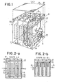
- the battery according to the invention is shown diagrammatically in Figure 1; in Figure 2 it is shown in section along AB and in Figure 3 in section along CD.
- the battery is made up of several elements 8 placed inside a case 1, separated by watertight partitions 7, and electrically connected in series. Each element comprises two plates forming the electrodes, the anode 3 and the cathode 4 leaving between them a space 5 necessary for the introduction of the electrolyte. Between each element a sealed passage 6 is made in the partition 7 making it possible to establish the electrical connection between the cathode of an element and the anode of the adjacent element.
- the battery is fitted, for example, to a system intended to be submerged in the sea, such as a drop-in ultrasonic radio buoy of an aircraft.
- the system being in normal operation, the stack is in the position for which the plate 2 defines the top of the stack while the plate 2 'defines the bottom.
- the battery is activated when all the elements 8 are filled with the electrolyte which is seawater.
- the battery according to the invention comprises arrangements for distributing the electrolyte, which make it possible to reduce the leakage electric currents.
- the stack has at least two outward openings 17 and 22 located respectively at the top and below. Each opening corresponds to the same network of tubes.
- Each network is composed of two coaxial tubes 11 and 12 whose axis is perpendicular to the partitions 7 and a series of tubes 10 connected perpendicularly to the tube 11, their ends opening out at each element so that the number of tubes 10 is equal the number of elements in the stack.
- One end of the tube 12 constitutes the only opening towards the outside, the other end opening into the tube 11.
- the sea water penetrates mainly through the opening located at the bottom 22, the hydrostatic pressure being higher there than at the level of the opening located at the top 17 and through which the air is expelled. .
- the path followed by the sea water towards the interior of the pile is constituted by the tube 12 then by the interval between the tube 12 and the tube 11 and by the tubes 10.
- a at the end of the filling, the two networks of tubes are filled with sea water and, during operation, the gas emissions are evacuated through the upper opening 17.
- the filling level depends on the one hand on the capillary pressure and on the hydrostatic pressure.
- the capillary pressure is inversely proportional to the radius of the tube 10, which has the smallest dimensions, and the filling level of the stack will be all the greater the lower the capillary pressure P of the tubes is compared to the difference in hydrostatic pressure. between the two openings 17 and 22.
- the filling time will be lower the larger the section of the tubes.
- An increase in the electrical resistance R implies an increase in the length £ of the tube and a decrease in the section s. However, by reducing the cross-section too much, the filling time would be increased and also the capillary pressure P which would limit the filling level.
- the tubes 10 of the two networks have sections chosen to obtain on the one hand a filling time compatible with the desired operational conditions, for example of the order of a minute, and on the other hand a filling level until the plates are completely immersed; and the lengths of these tubes are chosen as a function of the sections in order to obtain values of electrical resistances large enough to limit the leakage currents.
- FIG. 4 represents the electrical diagram equivalent to a distribution network.
- the electrical resistors 41, 42, 43, 44 are formed by the tubes 10 while the resistors 45, 46, 47 which are not equal are formed by the annular space between the tubes 11 and 12.
- the resistor 48 formed by the tube 12
- the openings 17 and 22 can be located on the face which corresponds to the terminal having the highest potential with respect to seawater. The path inside the tube 12 and then of the tube 11 between the external opening and the tube 10 of the element with the highest potential is thus maximum; moreover, the increase in the electrical resistance between seawater and an element is all the greater the higher the potential of this element.
- Batteries are often used, the anode of which consists of magnesium and the cathode of silver chloride, this electrochemical couple being very effective in a battery activated with salt water.
- Silver chloride is an expensive material and the limitation of the leakage currents obtained according to the invention makes it possible to reduce the mass of silver chloride by approximately 30% compared to non-closable batteries while maintaining identical performance in the same Terms of use.
- a 12 volt battery of this type has been produced comprising eight elements of 1.5 volts each in which the tubes are of circular section.
- Tubes such as 10 have a diameter of about 3mm with a length of about 30mm.
- the length and diameter of a tube 11 are respectively of the order of 55mm and 8mm while they are of the order of 32mm and 4mm for a tube 12.
- the complete filling time of this battery after immersion in salt water is of the order of a minute.
- the device described is simplified by eliminating the tubes 11 and 12 and causing the tubes 10 to open directly outwards or by eliminating the tube 12, the tube 11 opening directly outwards.
- the two tubes 11 are placed near the two opposite lateral faces of the stack, the tubes 10 of each network being oriented in opposite directions; for example the opening 22 would be located in the corner 30 in FIG. 1.
Landscapes
- Engineering & Computer Science (AREA)
- Manufacturing & Machinery (AREA)
- Chemical & Material Sciences (AREA)
- Chemical Kinetics & Catalysis (AREA)
- Electrochemistry (AREA)
- General Chemical & Material Sciences (AREA)
- Primary Cells (AREA)
- Hybrid Cells (AREA)
Applications Claiming Priority (2)
| Application Number | Priority Date | Filing Date | Title |
|---|---|---|---|
| FR7927221 | 1979-11-05 | ||
| FR7927221A FR2469011A1 (fr) | 1979-11-05 | 1979-11-05 | Pile activee a l'eau de mer |
Publications (3)
| Publication Number | Publication Date |
|---|---|
| EP0028566A2 true EP0028566A2 (de) | 1981-05-13 |
| EP0028566A3 EP0028566A3 (en) | 1981-05-27 |
| EP0028566B1 EP0028566B1 (de) | 1983-07-13 |
Family
ID=9231299
Family Applications (1)
| Application Number | Title | Priority Date | Filing Date |
|---|---|---|---|
| EP80401545A Expired EP0028566B1 (de) | 1979-11-05 | 1980-10-30 | Mit Meerwasser aktivierte Zelle |
Country Status (6)
| Country | Link |
|---|---|
| US (1) | US4338384A (de) |
| EP (1) | EP0028566B1 (de) |
| AU (1) | AU527875B2 (de) |
| CA (1) | CA1164935A (de) |
| DE (1) | DE3064150D1 (de) |
| FR (1) | FR2469011A1 (de) |
Families Citing this family (4)
| Publication number | Priority date | Publication date | Assignee | Title |
|---|---|---|---|---|
| FR2555366B1 (fr) * | 1983-11-22 | 1986-02-14 | France Etat Armement | Dispositif d'alimentation electrique amorcable par un liquide |
| US4745529A (en) * | 1986-10-06 | 1988-05-17 | Alupower, Inc. | Battery powered light source |
| ES1158584Y (es) * | 2016-04-05 | 2016-09-09 | Ramirez Alberto Andrés Santana | Central eléctrica iónica |
| US11697496B2 (en) * | 2019-12-18 | 2023-07-11 | United States Of America As Represented By The Secretary Of The Navy | Hybrid seawater battery for powering an unmanned aerial vehicle |
Family Cites Families (9)
| Publication number | Priority date | Publication date | Assignee | Title |
|---|---|---|---|---|
| US3177099A (en) * | 1965-04-06 | Ahjiivz ahvwihj wnishnovw icuiflo hjmoj hoih | ||
| GB1109923A (en) * | 1965-10-21 | 1968-04-18 | Dow Chemical Co | Low power output deferred action type primary battery |
| US3437529A (en) * | 1966-07-26 | 1969-04-08 | Esb Inc | Battery electrode-separator assembly |
| FR2053489A5 (en) * | 1969-07-07 | 1971-04-16 | Nuclear Research Associa | Salt water activated primary battery |
| GB1239526A (de) | 1969-07-23 | 1971-07-14 | ||
| DE2109034C3 (de) * | 1971-02-25 | 1978-10-12 | Siemens Ag, 1000 Berlin Und 8000 Muenchen | Batterie aus einer Mehrzahl von ZeUen |
| US3811945A (en) * | 1972-08-24 | 1974-05-21 | Consiglio Nazionale Ricerche | Electric battery |
| JPS4981839A (de) * | 1972-12-14 | 1974-08-07 | ||
| FR2333357A1 (fr) * | 1975-11-25 | 1977-06-24 | Accumulateurs Fixes | Batterie de generateurs electrochimiques |
-
1979
- 1979-11-05 FR FR7927221A patent/FR2469011A1/fr active Granted
-
1980
- 1980-10-29 AU AU63797/80A patent/AU527875B2/en not_active Ceased
- 1980-10-30 EP EP80401545A patent/EP0028566B1/de not_active Expired
- 1980-10-30 DE DE8080401545T patent/DE3064150D1/de not_active Expired
- 1980-11-03 CA CA000363848A patent/CA1164935A/en not_active Expired
- 1980-11-04 US US06/204,053 patent/US4338384A/en not_active Expired - Lifetime
Also Published As
| Publication number | Publication date |
|---|---|
| FR2469011A1 (fr) | 1981-05-08 |
| AU527875B2 (en) | 1983-03-24 |
| DE3064150D1 (en) | 1983-08-18 |
| EP0028566A3 (en) | 1981-05-27 |
| AU6379780A (en) | 1981-05-14 |
| US4338384A (en) | 1982-07-06 |
| FR2469011B1 (de) | 1982-02-26 |
| CA1164935A (en) | 1984-04-03 |
| EP0028566B1 (de) | 1983-07-13 |
Similar Documents
| Publication | Publication Date | Title |
|---|---|---|
| EP0531659B1 (de) | Elektrochemischer Generator mit hoher spezifischer Energie | |
| EP0948064B1 (de) | Prismatische aufladbare oder primäre Zelle mit steifem und zusammendrückendem Halter | |
| EP0059496B1 (de) | Elektrochemische Vorrichtung mit mindestens zwei Elementen in Serienschaltung | |
| CH625083A5 (de) | ||
| FR2696280A1 (fr) | Batterie multicellulaire compacte. | |
| FR3056022A1 (fr) | Dispositif d'interconnexion electrique d'elements de batterie et batterie d'accumulateurs pourvue d'un tel dispositif | |
| EP0271086B1 (de) | Elektrochemischer Generator mit Lithiumanode und flüssiger Kathode | |
| FR2927727A1 (fr) | Ensemble de stockage d'energie electrique multibobines. | |
| CA2230916A1 (fr) | Generateur electrochimique a securite amelioree | |
| EP0863564B1 (de) | Dünnschichtakkumulatorvorrichtung bestehend aus elektrochemischer Zelle und elektrischen Kontaktmitteln | |
| EP2127000A2 (de) | Sicherheitsvorrichtung für einen wasserdichten akkumulator | |
| FR3057108A1 (fr) | Accumulateur | |
| EP0232806B1 (de) | Aktivierbare Batterie auf Basis des Li/SO2Cl2 Paares | |
| EP0028566B1 (de) | Mit Meerwasser aktivierte Zelle | |
| FR2622358A1 (fr) | Structure de pile comprenant un montage d'electrodes enroulees et une fiche terminale telescopique | |
| CA1067146A (fr) | Pile a amorcage central | |
| FR3027737A1 (fr) | Dispositif electrochimique, tel qu'une microbatterie ou un systeme electrochrome, et son procede de realisation. | |
| EP0056759A2 (de) | Vorrichtung zum Zuführen und Abführen eines flüssigen Elektrolytes in einer Elektrolysezelle vom Filterpressentyp | |
| CA1122651A (fr) | Pile electrique cylindrique | |
| FR2627270A1 (fr) | Dispositif et procede pour detonateur de type " slapper " couple par noyau de ferrite | |
| CA1095587A (fr) | Generateur electrochimique de forme cylindrique | |
| FR2599895A1 (fr) | Accumulateur de reserve a elements multiples | |
| FR2485817A1 (fr) | Pile seche comportant des canaux de dispersion de l'electrolyte traversant le melange de la cathode et procede pour realiser une telle pile | |
| EP0061966B1 (de) | Herzstimulator mit einem einzigen Behälter zur Trennung der Mittel zur elektrischen Stromversorgung und zur Erzeugung von Impulsen | |
| FR2468212A1 (fr) | Perfectionnements apportes aux generateurs electrochimiques |
Legal Events
| Date | Code | Title | Description |
|---|---|---|---|
| PUAI | Public reference made under article 153(3) epc to a published international application that has entered the european phase |
Free format text: ORIGINAL CODE: 0009012 |
|
| PUAL | Search report despatched |
Free format text: ORIGINAL CODE: 0009013 |
|
| AK | Designated contracting states |
Designated state(s): DE GB IT NL |
|
| AK | Designated contracting states |
Designated state(s): DE GB IT NL |
|
| 17P | Request for examination filed |
Effective date: 19810606 |
|
| ITF | It: translation for a ep patent filed | ||
| GRAA | (expected) grant |
Free format text: ORIGINAL CODE: 0009210 |
|
| AK | Designated contracting states |
Designated state(s): DE GB IT NL |
|
| REF | Corresponds to: |
Ref document number: 3064150 Country of ref document: DE Date of ref document: 19830818 |
|
| PLBE | No opposition filed within time limit |
Free format text: ORIGINAL CODE: 0009261 |
|
| STAA | Information on the status of an ep patent application or granted ep patent |
Free format text: STATUS: NO OPPOSITION FILED WITHIN TIME LIMIT |
|
| 26N | No opposition filed | ||
| PGFP | Annual fee paid to national office [announced via postgrant information from national office to epo] |
Ref country code: NL Payment date: 19851031 Year of fee payment: 6 |
|
| PG25 | Lapsed in a contracting state [announced via postgrant information from national office to epo] |
Ref country code: NL Effective date: 19870501 |
|
| NLV4 | Nl: lapsed or anulled due to non-payment of the annual fee | ||
| PGFP | Annual fee paid to national office [announced via postgrant information from national office to epo] |
Ref country code: GB Payment date: 19910920 Year of fee payment: 12 |
|
| PGFP | Annual fee paid to national office [announced via postgrant information from national office to epo] |
Ref country code: DE Payment date: 19910924 Year of fee payment: 12 |
|
| ITTA | It: last paid annual fee | ||
| PG25 | Lapsed in a contracting state [announced via postgrant information from national office to epo] |
Ref country code: GB Effective date: 19921030 |
|
| GBPC | Gb: european patent ceased through non-payment of renewal fee |
Effective date: 19921030 |
|
| PG25 | Lapsed in a contracting state [announced via postgrant information from national office to epo] |
Ref country code: DE Effective date: 19930701 |