EP0028568A1 - Eichvorrichtung - Google Patents
Eichvorrichtung Download PDFInfo
- Publication number
- EP0028568A1 EP0028568A1 EP80401548A EP80401548A EP0028568A1 EP 0028568 A1 EP0028568 A1 EP 0028568A1 EP 80401548 A EP80401548 A EP 80401548A EP 80401548 A EP80401548 A EP 80401548A EP 0028568 A1 EP0028568 A1 EP 0028568A1
- Authority
- EP
- European Patent Office
- Prior art keywords
- piston
- cylinder
- meter
- gauge
- gauge according
- Prior art date
- Legal status (The legal status is an assumption and is not a legal conclusion. Google has not performed a legal analysis and makes no representation as to the accuracy of the status listed.)
- Granted
Links
- 239000007788 liquid Substances 0.000 claims abstract description 26
- 239000007789 gas Substances 0.000 claims description 16
- 238000004891 communication Methods 0.000 claims description 10
- 238000005259 measurement Methods 0.000 claims description 6
- 230000000717 retained effect Effects 0.000 claims description 3
- 238000006073 displacement reaction Methods 0.000 claims description 2
- 238000007789 sealing Methods 0.000 description 2
- 230000002411 adverse Effects 0.000 description 1
- 239000012080 ambient air Substances 0.000 description 1
- 238000007599 discharging Methods 0.000 description 1
- 230000000694 effects Effects 0.000 description 1
- 238000005516 engineering process Methods 0.000 description 1
- 239000002737 fuel gas Substances 0.000 description 1
- 238000010926 purge Methods 0.000 description 1
Images


Classifications
-
- G—PHYSICS
- G01—MEASURING; TESTING
- G01F—MEASURING VOLUME, VOLUME FLOW, MASS FLOW OR LIQUID LEVEL; METERING BY VOLUME
- G01F25/00—Testing or calibration of apparatus for measuring volume, volume flow or liquid level or for metering by volume
- G01F25/10—Testing or calibration of apparatus for measuring volume, volume flow or liquid level or for metering by volume of flowmeters
Definitions
- the present invention relates generally to the calibration of liquid meters and relates more particularly to a calibration gauge for liquefied gas meters.
- the meters must be calibrated and checked to check whether the volume of liquid passing through the meter corresponds to the value of the volume displayed on said meter during the passage of the liquid.
- the meter may, in the long run, present differences between the volume of liquid that it delivers and the volume of liquid that it indicates.
- standard tubes which consist of a tubular capacity closed at its ends and connectable to the meter to control.
- This capacity contains a sphere forming a piston which can move from one end to the other of the tube and in both directions under the effect of the liquid gas which circulates there.
- the display of the counter causing the emission of electrical pulses in constant number per unit of volume displayed, we count the number of pulses produced during the movement of the sphere which generates a standard volume, so that we can thus deduce the display error of the counter.
- standard gauges consisting of a piston on each face of which a rod is mounted, the assembly being able to slide freely and alternately in a cylinder defining a standard volume connectable to the meter to be checked.
- the object of the present invention is in particular to remedy these drawbacks, as well as all the shortcomings of previous gauges in general, by proposing a calibration gauge for liquefied gas meters, which makes it possible to carry out measurements under permanent flow at low flow rates, which solves the problem of temperature balancing during flow, and which therefore allows meter calibration with remarkable accuracy.
- the subject of the invention is a calibration gauge for a liquid meter, such as for example a liquefied gas, and of the type essentially comprising a piston, each face of which is provided with a rod and which is mounted freely sliding in a cylinder defining a reference volume and connected to said meter to allow the measurement of the possible difference existing between the value of the volume of liquid displayed by the meter and the volume of liquid which it delivers, characterized in that each said rod is hollow and in permanent communication with the cylinder chamber.
- the free end of a hollow rod communicates with the free end of the other hollow rod by a duct provided with at least one manual or automatic valve.
- one of the aforementioned rods comprises, in the vicinity of its free end, a contactor for controlling electrical pulses, which contactor cooperates with stops integral with the frame supporting the gauge.
- one of the aforementioned hollow rods contains a conduit integral with the piston and communicating with at least one bore formed radially in the piston and emerging in an annular groove machined in the periphery thereof .
- the periphery of the piston is provided with a friction ring axially retained by flanges, flanges or the like provided with seals.
- the communication of the hollow rods with the interior of the cylinder is ensured by orifices made radially in the said rods on each side of the piston.
- the cylinder is closed at each of its ends by a cylinder head with a friction ring for the hollow rods and in which cylinder head are provided passages for the sealed mounting of two pipes for supplying the liquid.
- stops cooperating with the contactor are mounted on a shaft carried by supports integral with the frame of the gauge, one of these stops being fixedly mounted on the shaft and the other stop being adjustable by following displacement the axis of said tree.
- the invention also relates to a meter for liquefied gas connected to a calibration gauge meeting the above-mentioned characteristics.
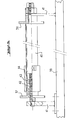
- a calibration gauge 1 essentially comprises a cylinder 2 in which can freely slide a piston 3 provided on each side with an internally hollow rod 4, 5.
- the cylinder 2 thus defines two chambers 6, 7 on either side of the piston 3.
- each hollow rod, 4, 5 has an internal and an axial channel 8, 9 respectively.
- the channel 8 of the rod 4 communicates permanently with the chamber 7 of the cylinder 2 through orifices 10, for example four in number , which are drilled radially in said rod 4 and are located in the vicinity of the corresponding face of the piston 3. It is the same for the channel 9 of the hollow rod 5 which communicates permanently with the chamber 6 of the cylinder 2 by orifices 11 made radially in said rod in the vicinity of the other face of the piston 3, as can be seen clearly in FIGS. 1 and 2.
- the end 8a of the channel 8 of the hollow rod 4 communicates with the end 9a of the channel 9 of the hollow rod 5 by a conduit 12 provided with at least one valve 13 which can be controlled manually or automatically.
- One of the hollow rods namely the rod 4 according to the example shown, is provided with a pipe or tube 14 which passes through the channel 8, which is fixed, for example screwed, at 15 to the piston 3 and which communicated with radial bores 16 formed in the piston 3 and opening into an annular groove 17 machined in the periphery of said piston.
- 18 has been shown in FIG. 2 an orifice ensuring communication between the tube 14 and the bores 16 which, according to a preferred embodiment, constitute four conduits intersecting in the center and opening into the groove 17.
- the tube 14 is equipped with a means 19 making it possible to permanently check the tightness between the chambers 6 and 7 of the cylinder 2.
- the periphery of the piston 3 is provided with a friction ring 20 axially retained by flanges 21 and flanges 22 secured to the piston 3 by means of screws 23.
- seals and seals 24 are provided between flanges 21 and cylinder 2, and also between flanges 21 and piston 3.
- the respective ends 4b and 5b of the hollow rods 4 and 5 ensure the centering of the flanges 21 on the piston 3.
- the cylinder 2 is closed at its ends by bottoms or cylinder heads 25 crossed by the hollow rods 4 and 5.
- the sealing of the rods passing through the cylinder heads 25 is essentially ensured by a sleeve or similar 26 comprising a seal 27 and a ring friction 28.
- the free end of the rods 4 and 5 is closed by a housing or the like 29 clamped between two flanges 30 and comprising an orifice 31 ensuring the communication of the end 8a of the channel 8 of the hollow rod 4 with the line 12 (FIG. 1) allowing the communication of the two hollow rods 4 and 5, and arranged parallel to the axis of the cylinder 2.
- Each cylinder head 25 has passages 32 for pipes 33 for supplying liquid. As seen in Figure 2, the passages 32 are arranged tangentially to the inner periphery of the cylinder 2 to allow on the one hand the gas purges at the high points of the cylinder, and on the other hand, the complete emptying at the low points .
- a contactor integral with the end of one of the hollow rods namely the rod 4 according to the example shown.
- This contactor can cooperate with two stops 37 and 38 integral with the frame 39 of the gauge according to the invention. More specifically, the stop 37 is adjustable relative to the frame 39, while the stop 38 is fixed, as will now be described in detail with reference to FIG. 3.
- the stops 37 and 38 are integral with a shaft 40 carried by supports 41 welded to the frame or chassis 39.
- the stop 38 is fixed, while the stop 37 is adjustable along the shaft 40 by being mounted on a nut 42 which can be screwed in one direction or the other t on the shaft 40 and which is lockable by means of a against nut 43.
- a ring covering the assembly which has just been described and which is thus advantageously inaccessible between two calibrations.
- the distance between the stops 37 and 38 must indeed be adjusted with great precision since, as will be seen later, it is it which, during the stroke of the piston 3 in the cylinder 1, will determine the reference volume measured .
- FIG. 1 Reference will now be made again to FIG. 1 to describe the connection of the gauge 1 according to the invention to a meter 50 for liquefied gases, it being understood that such a connection is not part of the present invention but is only described for understanding the operation of the calibration gauge 1 according to the invention.
- a liquefied gas storage tank has been shown at 51 which communicates by a conduit 52, 52a provided with a pump 53, with the input of the counter 50 making it possible to measure the flow of liquefied gas delivered by the tank 51 and indicated displayed on a volume indicator 54.
- this indicator 54 is associated an emitter 51 of electrical pulses having a resolution in relation to the required precision.
- a device 56 for counting the electrical pulses, supplied by a voltage source S, is connected on the one hand to the transmitter 55 and on the other hand to the contactor or detector 36.
- Line 52 returns to reservoir 51 via a line 57 fitted with a valve 58 for adjusting the flow rate by discharging part of the flow flow, and a valve 59 for adjusting the pressure so to obtain a value higher than the vapor pressure of the product for the current temperature.
- the output 60 of the counter 50 is connected by a line 61 to a circuit 70 equipped with four valves 62, 63, 64 and 65.
- a suitable mechanism (not shown) ensures the simultaneous control of the four valves so that a pair of valves diagonally opposite (for example 63 and 65) are open while the other two 62 and 64 are closed.
- a pair of valves diagonally opposite for example 63 and 65
- valve system 62 to 65 By a suitable arrangement of the valve system 62 to 65, that is to say for example in the state of opening of the valves 62 and 64 and closing of the valves 63 and 65, the liquid leaving the counter 50 is sent by the conduit 34 in the chamber 7 of the cylinder 2 on the side where the piston 3 is close to the cylinder head 25, as can be seen in FIG. 1. After a few centimeters of travel, the contactor 36 is tilted by the stop 37, as it can be seen in FIG. 1, which triggers the electronic counting of the pulses which are continuously emitted by the counter. It will be noted here that the display at 54 of the volume causes the emission of electrical pulses in constant number per unit of volume displayed.
- the contactor 36 strikes the fixed stop 38, which causes the pulse counting to stop. It then suffices to open the valve 13 so that the liquid continues to flow through the interior of the rods, that is to say from a rod to the other, it being understood, as we saw above, that the interior of the rods is itself in permanent communication with the interior of the cylinder 2.
- a piston calibration gauge has been produced, the essential elements of which (piston, rods, cylinders) are always maintained at the temperature of the liquid by a continuous circulation thereof, which allows to permanently evacuate any heat input from the outside and which therefore allows to perform a calibration with high precision.
- the mounting of the gauge of the invention was such that when the valve 13 was open, the chambers 6 and 7 of the cylinder 2 were in full communication with one another by means of the hollow rods 4 and 5.
Landscapes
- Physics & Mathematics (AREA)
- Fluid Mechanics (AREA)
- General Physics & Mathematics (AREA)
- Filling Or Discharging Of Gas Storage Vessels (AREA)
- Measurement Of Levels Of Liquids Or Fluent Solid Materials (AREA)
- Measurement Of Force In General (AREA)
- Pressure Sensors (AREA)
- Measuring Fluid Pressure (AREA)
- Electrical Discharge Machining, Electrochemical Machining, And Combined Machining (AREA)
- Amplifiers (AREA)
- Paper (AREA)
- Measuring Volume Flow (AREA)
- Sampling And Sample Adjustment (AREA)
Priority Applications (1)
| Application Number | Priority Date | Filing Date | Title |
|---|---|---|---|
| AT80401548T ATE2975T1 (de) | 1979-11-05 | 1980-10-30 | Eichvorrichtung. |
Applications Claiming Priority (2)
| Application Number | Priority Date | Filing Date | Title |
|---|---|---|---|
| FR7927210 | 1979-11-05 | ||
| FR7927210A FR2468890A1 (fr) | 1979-11-05 | 1979-11-05 | Jauge d'etalonnage |
Publications (2)
| Publication Number | Publication Date |
|---|---|
| EP0028568A1 true EP0028568A1 (de) | 1981-05-13 |
| EP0028568B1 EP0028568B1 (de) | 1983-04-06 |
Family
ID=9231291
Family Applications (1)
| Application Number | Title | Priority Date | Filing Date |
|---|---|---|---|
| EP80401548A Expired EP0028568B1 (de) | 1979-11-05 | 1980-10-30 | Eichvorrichtung |
Country Status (7)
| Country | Link |
|---|---|
| EP (1) | EP0028568B1 (de) |
| AT (1) | ATE2975T1 (de) |
| BE (1) | BE883557A (de) |
| DE (1) | DE3062643D1 (de) |
| ES (1) | ES8103373A1 (de) |
| FR (1) | FR2468890A1 (de) |
| PT (1) | PT71361A (de) |
Cited By (4)
| Publication number | Priority date | Publication date | Assignee | Title |
|---|---|---|---|---|
| WO1983002825A1 (en) * | 1982-02-16 | 1983-08-18 | Maurer, Robert | Meter provers |
| EP0109570A3 (en) * | 1982-10-23 | 1984-07-18 | Bopp & Reuther Gmbh | Device for testing flow meters |
| WO1987000622A1 (en) * | 1985-07-19 | 1987-01-29 | Flow Technology, Inc. | Apparatus and method for determining the flow characteristic of a volumetric flowmeter |
| CN108663099A (zh) * | 2017-04-01 | 2018-10-16 | 常州酷特仪器仪表有限公司 | 一种水表检定装置及检定方法 |
Citations (3)
| Publication number | Priority date | Publication date | Assignee | Title |
|---|---|---|---|---|
| FR1398872A (fr) * | 1964-04-01 | 1965-05-14 | Rochar Electronique | Banc d'étalonnage de mesureurs débitmétriques |
| US3673851A (en) * | 1970-08-18 | 1972-07-04 | Customline Control Products In | Meter proving system |
| US3877287A (en) * | 1972-02-27 | 1975-04-15 | Us Navy | Low flow gas or liquid calibrator |
-
1979
- 1979-11-05 FR FR7927210A patent/FR2468890A1/fr active Granted
-
1980
- 1980-05-30 BE BE0/200823A patent/BE883557A/fr not_active IP Right Cessation
- 1980-06-06 PT PT71361A patent/PT71361A/pt unknown
- 1980-06-17 ES ES492518A patent/ES8103373A1/es not_active Expired
- 1980-10-30 AT AT80401548T patent/ATE2975T1/de active
- 1980-10-30 EP EP80401548A patent/EP0028568B1/de not_active Expired
- 1980-10-30 DE DE8080401548T patent/DE3062643D1/de not_active Expired
Patent Citations (3)
| Publication number | Priority date | Publication date | Assignee | Title |
|---|---|---|---|---|
| FR1398872A (fr) * | 1964-04-01 | 1965-05-14 | Rochar Electronique | Banc d'étalonnage de mesureurs débitmétriques |
| US3673851A (en) * | 1970-08-18 | 1972-07-04 | Customline Control Products In | Meter proving system |
| US3877287A (en) * | 1972-02-27 | 1975-04-15 | Us Navy | Low flow gas or liquid calibrator |
Cited By (4)
| Publication number | Priority date | Publication date | Assignee | Title |
|---|---|---|---|---|
| WO1983002825A1 (en) * | 1982-02-16 | 1983-08-18 | Maurer, Robert | Meter provers |
| EP0109570A3 (en) * | 1982-10-23 | 1984-07-18 | Bopp & Reuther Gmbh | Device for testing flow meters |
| WO1987000622A1 (en) * | 1985-07-19 | 1987-01-29 | Flow Technology, Inc. | Apparatus and method for determining the flow characteristic of a volumetric flowmeter |
| CN108663099A (zh) * | 2017-04-01 | 2018-10-16 | 常州酷特仪器仪表有限公司 | 一种水表检定装置及检定方法 |
Also Published As
| Publication number | Publication date |
|---|---|
| BE883557A (fr) | 1980-09-15 |
| ES492518A0 (es) | 1981-02-16 |
| FR2468890A1 (fr) | 1981-05-08 |
| EP0028568B1 (de) | 1983-04-06 |
| ES8103373A1 (es) | 1981-02-16 |
| PT71361A (fr) | 1980-07-01 |
| DE3062643D1 (en) | 1983-05-11 |
| ATE2975T1 (de) | 1983-04-15 |
| FR2468890B1 (de) | 1981-11-06 |
Similar Documents
| Publication | Publication Date | Title |
|---|---|---|
| CA2314831C (fr) | Procede de controle du bon fonctionnement du systeme de recuperation de vapeur emise dans une installation de distribution de carburant ainsi qu'installation permettant la mise enoeuvre de ce procede | |
| EP0461943B1 (de) | Verdichtungsvorrichtung, insbesondere zur Druckfüllung eines Behälters | |
| FR2514076A1 (fr) | Procede et dispositif de mesure de quantites de carburant injectees par des pompes d'injection de moteurs a combustion interne | |
| FR2795139A1 (fr) | Dispositif permettant d'analyser instantanement le debit d'injection coup par coup fourni par un systeme d'injection utilise dans un moteur thermique | |
| EP0028568B1 (de) | Eichvorrichtung | |
| FR2737717A1 (fr) | Procede de recuperation de vapeur emise dans une installation de distribution de liquide | |
| FR2713300A1 (fr) | Dispositif de commande et de mesure d'écoulement. | |
| FR2720159A1 (fr) | Procédé et dispositif pour l'estimation de la poussée d'un statoréacteur. | |
| EP1643230B1 (de) | Verfahren und Vorrichtung zur Kontrolle der Dichtheit einer Umhüllung enthaltend ein Druckgas | |
| FR3100333B1 (fr) | Dispositif et procédé de détermination de paramètres caractéristiques des dimensions de nanoparticules | |
| CA2959939A1 (fr) | Couplemetre hydraulique | |
| EP0271516A1 (de) | Ventil zum verteilen von flüssigkeiten. | |
| EP0125992B1 (de) | Hydraulischer Stellmotor, insbesondere in Mikrobauweise, mit einer Halterung zum Anbringen von Zusatzelementen | |
| FR2580396A1 (fr) | Dispositif pour indiquer et/ou mesurer les ecoulements de matiere extremement faibles | |
| EP0076178A2 (de) | Verfahren und Vorrichtung zur Prüfung von montierten Vergasern | |
| EP0117207A1 (de) | Hydraulische Verteilereinrichtung | |
| FR2940262A1 (fr) | Mesureur volumetrique a deux pistons pour installation de distribution de carburant | |
| EP0425328A1 (de) | Verfahren und Vorrichtung zur Eichung eines Volumenzählers für beliebige Flüssigkeiten | |
| EP0518758B1 (de) | Verfahren und Vorrichtung zur Kontrolle der korrekten Durchführung einer Montage | |
| CA3059193A1 (fr) | Procede pour mesurer la quantite de gaz introduite dans un reservoir et station de remplissage | |
| FR2580803A1 (fr) | Banc de debitmetrie mobile | |
| FR2663118A1 (fr) | Procede pour la mesure en vue du reglage du debit de conduites transportant un fluide de regulation thermique, et dispositif de mise en óoeuvre du procede. | |
| FR2570187A1 (fr) | Procede et dispositif de detection et de localisation des fuites dans un echangeur de chaleur a faisceau tubulaire a l'arret | |
| FR2558254A1 (fr) | Dispositif de mesure de pression d'un liquide | |
| BE686121A (de) |
Legal Events
| Date | Code | Title | Description |
|---|---|---|---|
| PUAI | Public reference made under article 153(3) epc to a published international application that has entered the european phase |
Free format text: ORIGINAL CODE: 0009012 |
|
| AK | Designated contracting states |
Designated state(s): AT CH DE GB NL |
|
| TCAT | At: translation of patent claims filed | ||
| 17P | Request for examination filed |
Effective date: 19810731 |
|
| DET | De: translation of patent claims | ||
| GRAA | (expected) grant |
Free format text: ORIGINAL CODE: 0009210 |
|
| AK | Designated contracting states |
Designated state(s): AT CH DE GB LI NL |
|
| REF | Corresponds to: |
Ref document number: 2975 Country of ref document: AT Date of ref document: 19830415 Kind code of ref document: T |
|
| REF | Corresponds to: |
Ref document number: 3062643 Country of ref document: DE Date of ref document: 19830511 |
|
| PGFP | Annual fee paid to national office [announced via postgrant information from national office to epo] |
Ref country code: AT Payment date: 19901011 Year of fee payment: 11 |
|
| PGFP | Annual fee paid to national office [announced via postgrant information from national office to epo] |
Ref country code: GB Payment date: 19901019 Year of fee payment: 11 |
|
| PGFP | Annual fee paid to national office [announced via postgrant information from national office to epo] |
Ref country code: NL Payment date: 19901031 Year of fee payment: 11 |
|
| PGFP | Annual fee paid to national office [announced via postgrant information from national office to epo] |
Ref country code: CH Payment date: 19901102 Year of fee payment: 11 |
|
| PGFP | Annual fee paid to national office [announced via postgrant information from national office to epo] |
Ref country code: DE Payment date: 19901130 Year of fee payment: 11 |
|
| PG25 | Lapsed in a contracting state [announced via postgrant information from national office to epo] |
Ref country code: GB Effective date: 19911030 Ref country code: AT Effective date: 19911030 |
|
| PG25 | Lapsed in a contracting state [announced via postgrant information from national office to epo] |
Ref country code: LI Effective date: 19911031 Ref country code: CH Effective date: 19911031 |
|
| PG25 | Lapsed in a contracting state [announced via postgrant information from national office to epo] |
Ref country code: NL Effective date: 19920501 |
|
| NLV4 | Nl: lapsed or anulled due to non-payment of the annual fee | ||
| GBPC | Gb: european patent ceased through non-payment of renewal fee | ||
| REG | Reference to a national code |
Ref country code: CH Ref legal event code: PL |
|
| PG25 | Lapsed in a contracting state [announced via postgrant information from national office to epo] |
Ref country code: DE Effective date: 19920701 |
|
| PLBE | No opposition filed within time limit |
Free format text: ORIGINAL CODE: 0009261 |
|
| STAA | Information on the status of an ep patent application or granted ep patent |
Free format text: STATUS: NO OPPOSITION FILED WITHIN TIME LIMIT |