EP0028664B1 - Tête de dispersion de fluide - Google Patents
Tête de dispersion de fluide Download PDFInfo
- Publication number
- EP0028664B1 EP0028664B1 EP19790200733 EP79200733A EP0028664B1 EP 0028664 B1 EP0028664 B1 EP 0028664B1 EP 19790200733 EP19790200733 EP 19790200733 EP 79200733 A EP79200733 A EP 79200733A EP 0028664 B1 EP0028664 B1 EP 0028664B1
- Authority
- EP
- European Patent Office
- Prior art keywords
- valve
- spring
- disc
- deflection screen
- distributor head
- Prior art date
- Legal status (The legal status is an assumption and is not a legal conclusion. Google has not performed a legal analysis and makes no representation as to the accuracy of the status listed.)
- Expired
Links
- 239000007788 liquid Substances 0.000 title claims abstract description 13
- 230000001681 protective effect Effects 0.000 claims abstract description 5
- 239000007921 spray Substances 0.000 claims description 5
- XLYOFNOQVPJJNP-UHFFFAOYSA-N water Substances O XLYOFNOQVPJJNP-UHFFFAOYSA-N 0.000 description 8
- 230000003628 erosive effect Effects 0.000 description 3
- 239000012634 fragment Substances 0.000 description 2
- 239000012267 brine Substances 0.000 description 1
- 230000007797 corrosion Effects 0.000 description 1
- 238000005260 corrosion Methods 0.000 description 1
- 230000001419 dependent effect Effects 0.000 description 1
- 230000008020 evaporation Effects 0.000 description 1
- 238000001704 evaporation Methods 0.000 description 1
- 239000000463 material Substances 0.000 description 1
- 230000000717 retained effect Effects 0.000 description 1
- HPALAKNZSZLMCH-UHFFFAOYSA-M sodium;chloride;hydrate Chemical compound O.[Na+].[Cl-] HPALAKNZSZLMCH-UHFFFAOYSA-M 0.000 description 1
- 239000000243 solution Substances 0.000 description 1
- 238000009692 water atomization Methods 0.000 description 1
Images
Classifications
-
- B—PERFORMING OPERATIONS; TRANSPORTING
- B05—SPRAYING OR ATOMISING IN GENERAL; APPLYING FLUENT MATERIALS TO SURFACES, IN GENERAL
- B05B—SPRAYING APPARATUS; ATOMISING APPARATUS; NOZZLES
- B05B1/00—Nozzles, spray heads or other outlets, with or without auxiliary devices such as valves, heating means
- B05B1/30—Nozzles, spray heads or other outlets, with or without auxiliary devices such as valves, heating means designed to control volume of flow, e.g. with adjustable passages
- B05B1/32—Nozzles, spray heads or other outlets, with or without auxiliary devices such as valves, heating means designed to control volume of flow, e.g. with adjustable passages in which a valve member forms part of the outlet opening
- B05B1/323—Nozzles, spray heads or other outlets, with or without auxiliary devices such as valves, heating means designed to control volume of flow, e.g. with adjustable passages in which a valve member forms part of the outlet opening the valve member being actuated by the pressure of the fluid to be sprayed
-
- B—PERFORMING OPERATIONS; TRANSPORTING
- B01—PHYSICAL OR CHEMICAL PROCESSES OR APPARATUS IN GENERAL
- B01D—SEPARATION
- B01D19/00—Degasification of liquids
- B01D19/0063—Regulation, control including valves and floats
-
- Y—GENERAL TAGGING OF NEW TECHNOLOGICAL DEVELOPMENTS; GENERAL TAGGING OF CROSS-SECTIONAL TECHNOLOGIES SPANNING OVER SEVERAL SECTIONS OF THE IPC; TECHNICAL SUBJECTS COVERED BY FORMER USPC CROSS-REFERENCE ART COLLECTIONS [XRACs] AND DIGESTS
- Y10—TECHNICAL SUBJECTS COVERED BY FORMER USPC
- Y10T—TECHNICAL SUBJECTS COVERED BY FORMER US CLASSIFICATION
- Y10T137/00—Fluid handling
- Y10T137/7722—Line condition change responsive valves
- Y10T137/7837—Direct response valves [i.e., check valve type]
- Y10T137/7904—Reciprocating valves
- Y10T137/7922—Spring biased
- Y10T137/7923—With means to protect spring from fluid
Definitions
- the invention relates to a liquid distribution head for a mixed preheater degasser in steam power plants according to the preamble of claim 1.
- a water atomizing nozzle which consists of a spring-loaded valve which is arranged in a water inlet chamber on the upper part of a mixing preheater in such a way that the valve with the valve plate, valve spring and spring plate from a deflection housing is surrounded.
- the moving parts of the valve, in particular the valve spring, the valve plate and the valve stem, are washed by the water.
- a disadvantage of this arrangement is that the parts exposed to the water flow are at high risk of erosion.
- the work is very time-consuming for assembly or revisions during this training.
- the advantage of the valve design according to the invention is that if a spring breaks, the fragments between the protective housing and the spring plate are retained and cannot fall into the preheater.
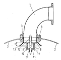
- valve 7 designed as a spray insert, which consists of a valve plate 8, a valve stem 9, a valve spring 10 and a spring plate 11.
- the valve 7 is arranged by means of a bracket 12 in the flange 3, together with a frusto-conical deflecting screen 13 so that its inner surface distributes the water sprayed through the valve 7 onto the cylindrical part of the inner surface of the mixing preheater.
- the valve spring 10 is surrounded by an annular protective housing 14 which rests on the valve plate 8. This ensures that no fragments fall into the mixer preheater if the spring breaks.
- the protective housing 14 can also consist of two housing halves which slide concentrically into one another during spring movements.
- the water is dissolved into sufficiently fine drops regardless of the water throughput.
- the pressure required to spray the water is relatively low. Accordingly, the tension of the valve spring 10 is set via the spring plate 11.
- the pressure loss of the injected water is also kept within modest limits; the pressure drop is on the order of 3 to 5 mWS over the entire range.
- valve design according to the invention largely prevents clogging of the spray insert.
- a spray insert can also be used for all other liquids in other areas of application, for example in brine evaporation, since only a few parts have to consist of corrosion and erosion-resistant material.
Landscapes
- Chemical & Material Sciences (AREA)
- Chemical Kinetics & Catalysis (AREA)
- Particle Formation And Scattering Control In Inkjet Printers (AREA)
- Nozzles (AREA)
- Lift Valve (AREA)
- Sampling And Sample Adjustment (AREA)
- Feeding, Discharge, Calcimining, Fusing, And Gas-Generation Devices (AREA)
- Automatic Analysis And Handling Materials Therefor (AREA)
Claims (3)
Priority Applications (1)
| Application Number | Priority Date | Filing Date | Title |
|---|---|---|---|
| AT79200733T ATE7207T1 (de) | 1979-11-08 | 1979-12-06 | Fluessigkeitsverteilkopf. |
Applications Claiming Priority (2)
| Application Number | Priority Date | Filing Date | Title |
|---|---|---|---|
| CH999979 | 1979-11-08 | ||
| CH9999/79 | 1979-11-08 |
Publications (2)
| Publication Number | Publication Date |
|---|---|
| EP0028664A1 EP0028664A1 (fr) | 1981-05-20 |
| EP0028664B1 true EP0028664B1 (fr) | 1984-04-25 |
Family
ID=4358025
Family Applications (1)
| Application Number | Title | Priority Date | Filing Date |
|---|---|---|---|
| EP19790200733 Expired EP0028664B1 (fr) | 1979-11-08 | 1979-12-06 | Tête de dispersion de fluide |
Country Status (6)
| Country | Link |
|---|---|
| US (1) | US4404929A (fr) |
| EP (1) | EP0028664B1 (fr) |
| AT (1) | ATE7207T1 (fr) |
| AU (1) | AU545814B2 (fr) |
| CA (1) | CA1148424A (fr) |
| DE (2) | DE2966940D1 (fr) |
Families Citing this family (5)
| Publication number | Priority date | Publication date | Assignee | Title |
|---|---|---|---|---|
| ES2001332A6 (es) * | 1985-07-02 | 1988-05-16 | Framatome Sa | Generador de vapor |
| US4698076A (en) * | 1986-04-14 | 1987-10-06 | Martin Bekedam | Atmospheric deaerator unit |
| US4874406A (en) * | 1988-11-28 | 1989-10-17 | Martin Bekedam | Jet spray atmospheric deaerator |
| GB0804135D0 (en) * | 2008-03-06 | 2008-04-09 | Rigcool Ltd | Nozzle |
| EP2574387A1 (fr) | 2011-09-27 | 2013-04-03 | Stork Thermeq B.V. | Dégazeur de type aérosol |
Family Cites Families (12)
| Publication number | Priority date | Publication date | Assignee | Title |
|---|---|---|---|---|
| US272684A (en) * | 1883-02-20 | Feed-water heater for steam-boilers | ||
| CH308A (de) * | 1889-01-02 | 1889-03-08 | Hugo Mestern | Brause für Ventilation, Heizung oder Kühlung |
| FR562215A (fr) * | 1922-04-04 | 1923-11-07 | Compresseur d'air | |
| FR562219A (fr) | 1922-04-05 | 1923-11-07 | Appareil d'arrosage | |
| US1842962A (en) * | 1925-12-21 | 1932-01-26 | Anna M C Wechsberg | Locomotive feed water heater |
| US1828473A (en) * | 1929-12-17 | 1931-10-20 | C S Engineering Co | Feed water heating apparatus |
| US2207758A (en) * | 1938-04-08 | 1940-07-16 | Paul E Rehse | Hose nozzle |
| US2422059A (en) * | 1943-12-14 | 1947-06-10 | Fred B Wilber | Lawn sprinkler |
| US2582527A (en) * | 1947-11-14 | 1952-01-15 | Gerber Prod | Nozzle valve |
| US2689018A (en) * | 1951-06-11 | 1954-09-14 | American Water Softener Co | Apparatus and method for deaerating water |
| US2671524A (en) * | 1951-07-14 | 1954-03-09 | Permutit Co | Water deaerating |
| US3904125A (en) * | 1974-03-14 | 1975-09-09 | Premier Ind Corp | Constant pressure nozzle discharge mechanism |
-
1979
- 1979-12-06 EP EP19790200733 patent/EP0028664B1/fr not_active Expired
- 1979-12-06 AT AT79200733T patent/ATE7207T1/de not_active IP Right Cessation
- 1979-12-06 DE DE7979200733T patent/DE2966940D1/de not_active Expired
-
1980
- 1980-01-16 DE DE19808000930U patent/DE8000930U1/de not_active Expired
- 1980-11-06 AU AU64147/80A patent/AU545814B2/en not_active Expired
- 1980-11-07 CA CA000364309A patent/CA1148424A/fr not_active Expired
-
1982
- 1982-06-01 US US06/383,818 patent/US4404929A/en not_active Expired - Lifetime
Also Published As
| Publication number | Publication date |
|---|---|
| US4404929A (en) | 1983-09-20 |
| EP0028664A1 (fr) | 1981-05-20 |
| CA1148424A (fr) | 1983-06-21 |
| AU545814B2 (en) | 1985-08-01 |
| AU6414780A (en) | 1981-05-14 |
| DE2966940D1 (en) | 1984-05-30 |
| DE8000930U1 (de) | 1981-04-23 |
| ATE7207T1 (de) | 1984-05-15 |
Similar Documents
| Publication | Publication Date | Title |
|---|---|---|
| DE69521976T2 (de) | Strahldüse für die Anwendung im katalytischen Wirbelschicht-Krackverfahren | |
| DE3514287A1 (de) | Druckluft-betriebene spruehduese | |
| DE2422868B2 (de) | Mehrköpfige Spritzpistole | |
| DE69303905T2 (de) | Verfahren und vorrichtung zum erniedrigen von druck und temperatur von dampf in einem dampfaufbereitungsventil | |
| DE3820537A1 (de) | Spruehvorrichtung | |
| DE2620881C3 (de) | Zerstäuberdüse | |
| DE2061837A1 (de) | Verfahren zur Durchführung von Niedrigtemperatur-Mahlprozessen in einer Schwingmühle | |
| EP0028664A1 (fr) | Tête de dispersion de fluide | |
| DE712163C (de) | Vorrichtung zum gleichzeitigen Kuehlen und Entspannen von ueberhitztem Dampf | |
| DE1261788B (de) | Spritzpistole | |
| DE2720458A1 (de) | Duese zum verspruehen von fluessigprodukten | |
| EP0459096A1 (fr) | Buse de forme plane | |
| DE581826C (de) | Vorrichtung zum Herstellen von Emulsionen | |
| AT395638B (de) | Einspritzduese fuer brennkraftmaschinen, insbesondere dieselmotoren | |
| DE755081C (de) | Einhaengevorrichtung fuer Gaserzeuger | |
| DE702485C (de) | Verfahren zum Spritzen von fluessigen bzw. Aufstaeuben von staubfoermigen Stoffen mittels Druckluft oder anderer gasfoermiger Druckmittel | |
| DE2854326A1 (de) | Elektrostatische farbspritzpistole mit rotierender zerstaeuberglocke | |
| AT52460B (de) | Zerstäuber für pulverförmige Stoffe. | |
| EP1564486A2 (fr) | Procédé et dispositif de pulvérisation du combustible liquide pour un appareil de combustion | |
| DE3619857A1 (de) | Verfahren und vorrichtung zur zerstaeubung von fluessigen und/oder pastoesen und/oder pulverfoermigen medien, insbesondere von fluessigkeiten mit teilchen, beispielsweise abrasiven teilchen | |
| DE19819004C2 (de) | Vorrichtung zum Verteilen eines Fluids | |
| AT229996B (de) | Spritzpistole | |
| DE297274C (fr) | ||
| DE2103362A1 (de) | Vorrichtung zum Mischen verschiedenartiger Flüssigkeiten | |
| DE272486C (fr) |
Legal Events
| Date | Code | Title | Description |
|---|---|---|---|
| PUAI | Public reference made under article 153(3) epc to a published international application that has entered the european phase |
Free format text: ORIGINAL CODE: 0009012 |
|
| AK | Designated contracting states |
Designated state(s): AT CH DE NL SE |
|
| RBV | Designated contracting states (corrected) |
Designated state(s): AT CH DE NL SE |
|
| RAP1 | Party data changed (applicant data changed or rights of an application transferred) |
Owner name: BBC AKTIENGESELLSCHAFT BROWN, BOVERI & CIE. |
|
| 17P | Request for examination filed |
Effective date: 19811008 |
|
| GRAA | (expected) grant |
Free format text: ORIGINAL CODE: 0009210 |
|
| AK | Designated contracting states |
Designated state(s): AT CH DE NL SE |
|
| REF | Corresponds to: |
Ref document number: 7207 Country of ref document: AT Date of ref document: 19840515 Kind code of ref document: T |
|
| REF | Corresponds to: |
Ref document number: 2966940 Country of ref document: DE Date of ref document: 19840530 |
|
| PLBE | No opposition filed within time limit |
Free format text: ORIGINAL CODE: 0009261 |
|
| STAA | Information on the status of an ep patent application or granted ep patent |
Free format text: STATUS: NO OPPOSITION FILED WITHIN TIME LIMIT |
|
| 26N | No opposition filed | ||
| PGFP | Annual fee paid to national office [announced via postgrant information from national office to epo] |
Ref country code: CH Payment date: 19930309 Year of fee payment: 14 |
|
| PG25 | Lapsed in a contracting state [announced via postgrant information from national office to epo] |
Ref country code: CH Effective date: 19931231 |
|
| REG | Reference to a national code |
Ref country code: CH Ref legal event code: PL |
|
| EAL | Se: european patent in force in sweden |
Ref document number: 79200733.8 |
|
| PGFP | Annual fee paid to national office [announced via postgrant information from national office to epo] |
Ref country code: AT Payment date: 19951122 Year of fee payment: 17 |
|
| PG25 | Lapsed in a contracting state [announced via postgrant information from national office to epo] |
Ref country code: AT Effective date: 19961206 |
|
| PGFP | Annual fee paid to national office [announced via postgrant information from national office to epo] |
Ref country code: SE Payment date: 19981118 Year of fee payment: 20 Ref country code: DE Payment date: 19981118 Year of fee payment: 20 |
|
| PGFP | Annual fee paid to national office [announced via postgrant information from national office to epo] |
Ref country code: NL Payment date: 19981123 Year of fee payment: 20 |
|
| PG25 | Lapsed in a contracting state [announced via postgrant information from national office to epo] |
Ref country code: NL Free format text: LAPSE BECAUSE OF EXPIRATION OF PROTECTION Effective date: 19991206 |
|
| PG25 | Lapsed in a contracting state [announced via postgrant information from national office to epo] |
Ref country code: SE Free format text: THE PATENT HAS BEEN ANNULLED BY A DECISION OF A NATIONAL AUTHORITY Effective date: 19991230 |
|
| NLV7 | Nl: ceased due to reaching the maximum lifetime of a patent |
Effective date: 19991206 |
|
| EUG | Se: european patent has lapsed |
Ref document number: 79200733.8 |