EP0028735A2 - Centre d'usinage équipé d'un robot - Google Patents
Centre d'usinage équipé d'un robot Download PDFInfo
- Publication number
- EP0028735A2 EP0028735A2 EP80106430A EP80106430A EP0028735A2 EP 0028735 A2 EP0028735 A2 EP 0028735A2 EP 80106430 A EP80106430 A EP 80106430A EP 80106430 A EP80106430 A EP 80106430A EP 0028735 A2 EP0028735 A2 EP 0028735A2
- Authority
- EP
- European Patent Office
- Prior art keywords
- robot device
- workpiece
- machining center
- tool
- machine body
- Prior art date
- Legal status (The legal status is an assumption and is not a legal conclusion. Google has not performed a legal analysis and makes no representation as to the accuracy of the status listed.)
- Granted
Links
Images

Classifications
-
- B—PERFORMING OPERATIONS; TRANSPORTING
- B23—MACHINE TOOLS; METAL-WORKING NOT OTHERWISE PROVIDED FOR
- B23Q—DETAILS, COMPONENTS, OR ACCESSORIES FOR MACHINE TOOLS, e.g. ARRANGEMENTS FOR COPYING OR CONTROLLING; MACHINE TOOLS IN GENERAL CHARACTERISED BY THE CONSTRUCTION OF PARTICULAR DETAILS OR COMPONENTS; COMBINATIONS OR ASSOCIATIONS OF METAL-WORKING MACHINES, NOT DIRECTED TO A PARTICULAR RESULT
- B23Q7/00—Arrangements for handling work specially combined with or arranged in, or specially adapted for use in connection with, machine tools, e.g. for conveying, loading, positioning, discharging, sorting
- B23Q7/04—Arrangements for handling work specially combined with or arranged in, or specially adapted for use in connection with, machine tools, e.g. for conveying, loading, positioning, discharging, sorting by means of grippers
- B23Q7/046—Handling workpieces or tools
-
- B—PERFORMING OPERATIONS; TRANSPORTING
- B23—MACHINE TOOLS; METAL-WORKING NOT OTHERWISE PROVIDED FOR
- B23Q—DETAILS, COMPONENTS, OR ACCESSORIES FOR MACHINE TOOLS, e.g. ARRANGEMENTS FOR COPYING OR CONTROLLING; MACHINE TOOLS IN GENERAL CHARACTERISED BY THE CONSTRUCTION OF PARTICULAR DETAILS OR COMPONENTS; COMBINATIONS OR ASSOCIATIONS OF METAL-WORKING MACHINES, NOT DIRECTED TO A PARTICULAR RESULT
- B23Q3/00—Devices holding, supporting, or positioning work or tools, of a kind normally removable from the machine
- B23Q3/155—Arrangements for automatic insertion or removal of tools, e.g. combined with manual handling
- B23Q3/157—Arrangements for automatic insertion or removal of tools, e.g. combined with manual handling of rotary tools
- B23Q3/15713—Arrangements for automatic insertion or removal of tools, e.g. combined with manual handling of rotary tools a transfer device taking a single tool from a storage device and inserting it in a spindle
-
- Y—GENERAL TAGGING OF NEW TECHNOLOGICAL DEVELOPMENTS; GENERAL TAGGING OF CROSS-SECTIONAL TECHNOLOGIES SPANNING OVER SEVERAL SECTIONS OF THE IPC; TECHNICAL SUBJECTS COVERED BY FORMER USPC CROSS-REFERENCE ART COLLECTIONS [XRACs] AND DIGESTS
- Y10—TECHNICAL SUBJECTS COVERED BY FORMER USPC
- Y10S—TECHNICAL SUBJECTS COVERED BY FORMER USPC CROSS-REFERENCE ART COLLECTIONS [XRACs] AND DIGESTS
- Y10S483/00—Tool changing
- Y10S483/901—Robot end effectors
-
- Y—GENERAL TAGGING OF NEW TECHNOLOGICAL DEVELOPMENTS; GENERAL TAGGING OF CROSS-SECTIONAL TECHNOLOGIES SPANNING OVER SEVERAL SECTIONS OF THE IPC; TECHNICAL SUBJECTS COVERED BY FORMER USPC CROSS-REFERENCE ART COLLECTIONS [XRACs] AND DIGESTS
- Y10—TECHNICAL SUBJECTS COVERED BY FORMER USPC
- Y10T—TECHNICAL SUBJECTS COVERED BY FORMER US CLASSIFICATION
- Y10T483/00—Tool changing
- Y10T483/16—Tool changing with means to transfer work
-
- Y—GENERAL TAGGING OF NEW TECHNOLOGICAL DEVELOPMENTS; GENERAL TAGGING OF CROSS-SECTIONAL TECHNOLOGIES SPANNING OVER SEVERAL SECTIONS OF THE IPC; TECHNICAL SUBJECTS COVERED BY FORMER USPC CROSS-REFERENCE ART COLLECTIONS [XRACs] AND DIGESTS
- Y10—TECHNICAL SUBJECTS COVERED BY FORMER USPC
- Y10T—TECHNICAL SUBJECTS COVERED BY FORMER US CLASSIFICATION
- Y10T483/00—Tool changing
- Y10T483/17—Tool changing including machine tool or component
- Y10T483/1733—Rotary spindle machine tool [e.g., milling machine, boring, machine, grinding machine, etc.]
- Y10T483/1748—Tool changer between spindle and matrix
- Y10T483/1752—Tool changer between spindle and matrix including tool holder pivotable about axis
- Y10T483/1779—Linearly movable tool holder
Definitions
- This invention relates to a machining center equipped with a robot device, wherein the robot device, having a manipulating hand, is integrally incorporated in a machine body of the machining center.
- a machining center equipped with an automatic tool changer and capable of automatically exchanging tools between a tool storing magazine and a spindle of a machine body for applying various machining operations onto a workpiece to be processed has been widely practiced.
- a robot device conventionally referred to as an industrial robot which automatically performs, for labor saving, a workpiece setting operation comprising setting a workpiece to be machined (hereinafter referred to as a "workpiece") onto an automatically controlled machine tool from a workpiece supplying table and returning the workpiece after completion of machining to the workpiece supplying table from the automatically controlled machine tool.
- the robot device is separately provided and disposed adjacent to the machining center to supply workpieces to the machining center from the workpiece supplying table which is also disposed near the machining center.
- Automatic exchange of tools is carried out by the automatic tool changer mounted on the.machining center, and the robot device does not participate in such an automatic tool exchanging operation. Therefore, this conventional machining center requires and occupies a considerable space in a maching working site for floor spaces covered by the workpiece supplying table and the robot device as well as the machining center and a working space for conveying the workpiece from the workpiece supplying table to the machining center by the robot device and vice versa. This increases a plant investment and, accordingly, increases the machining cost of the workpiece.
- Such a discretely provided robot device has a moving guide for guiding a manipulating hand and a robot arm on a base of the robot device, it has, in general, a limit in mechanical rigidity and has a limit in size and weight of the workpiece to be conveyed.
- an object of the present invention to provide a machining center equipped with a robot device wherein the robot device, having a.manipulating hand is integrally incorporated in a machine body for reducing a space occupied by installations in a machine working site, limiting the working space of the robot device to a definite minimum space in the vicinity of the machine body to assure operational safety and increasing the mechanical rigidity of the robot device.
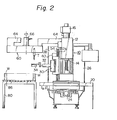
- Fig. 1 is a plan view of an embodiment of a machining center equipped with a robot device in accordance with the present invention and Fig. 2 is a front view of the same.
- the machining center is comprised of a machine body 10, a robot device 30 and a tool storing magazine 60.
- a workpiece supplying table 80 is provided in close vicinity to the machining center.
- the machine body 1 0 has a stationary column 12, and a spindle 14 fitted in a spindle head and disposed in front of the stationary column 12 and adapted to be driven and rotated by a spindle drive motor 16.
- the spindle 14 is movable, conjointly with the spindle head, in the vertical direction along a vertical guide shaft 18.
- a work table 20 is also disposed in front of the stationary column 12 so that it may be movable within a horizontal plane in a lateral, X-axis direction and in a Y -axis direction perpendicular to the X-axis direction along a slide 22.
- Reference numeral 24 designates a Y-axis motor for driving the work table 20 in the Y-axis direction.
- Another motor (not illustrated) is provided to drive the work table 20 in the X-axis direction.
- On opposite sides of the stationary column 12 there are provided a numerical control device 26 and an electric control device 28.
- the robot device 30 which is movable in the vertical direction along a vertical guide rod 12a is integrally imcorporated in the machine body 10 on a sidewall of the stationary column 12.
- the robot device 30 has a robot arm 32 extending in the horizontal direction and a manipularing hand 34 provided at a tip end of the robot arm 32.
- the robot arm 32 and the manipulating hand 34 are adapted to turn around a pivot shaft 36 along a radial trajectory designated by reference "A" in Fig. 1.
- 38 is a guide block of the robot device 30 which is engaged with the linear guide rod 12a. The structure and operation of the robot device 30 will be described in detail later.
- the tool storing magazine 60 is disposed at the side of the stationary column 12 and connected to an upper end portion of the stationary column 12 of the machine body 10 through an arm 64.
- the tool storing magazine 60 holds a plurality of cutting tools T set in respective tool arbors as in a tool storing magazine of a known automatic tool changer.
- the cutting tools T are moved along a given trajectory by a chain drive mechanism 62 which is driven by a rotating drive motor 66 and, in mid course, each tool passes a preselected position P for tool exchanging.
- a workpiece supplying table 80 is disposed on a floor near the machine body 10.
- the workpiece supplying table 80 is comprised, for example, of an elliptical workpiece retaining table 82 as depicted and a plurality of sub-tables 84 which move around the workpiece retaining table 82.
- the circular movement of the sub-tables 84 is carried out by such an arrangement that the sub-tables 84 are connected to a conventional endless chain mechanism which makes circular movement by a drive motor (not illustrated) and the sub-tables 84 are each provided with rollers 86 to enable the sub-tables 84 to move around the workpiece retaining table 82.
- Each of the sub-tables 84 holds a workpiece W thereon which has been supplied from the workpiece retaining table 82 and is moved to pass a position Q for delivering the workpiece W.
- the above-described preselected position P for tool exchanging and the workpiece delivering position Q are both on the working trajectory A of the manipulating hand 34 and the positions P and Q are suitably spaced from each other.
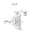
- the robot device 30 of the present invention will now be described in connection with a schematically diagrammatic view of the device 30 illustrated in Fig. 3.
- the same reference numerals as those used in Figs. 1 and 2 designate the same parts, respectively.
- the robot device 30 is mounted by the guide block 38 so that it may slide in a vertical direction along the vertical guide rod 12a formed integrally with the stationary column 12. More specifically, since the load of the robot device itself is supported by the stationary column 12 of the machine body 10, the robot device 30 of the present invention is more advantageous than the conventional separately provided robot device in that the mechanical rigidity of the present robot device is highly increased.
- the vertical sliding movement of the robot device 30 is attained through engagement between a ball screw shaft 54 which is rotatably supported by the stationary column 12 through a bearing 58 and a ball nut 56 provided inside the robot device 30.
- a ball screw shaft 54 which is rotatably supported by the stationary column 12 through a bearing 58 and a ball nut 56 provided inside the robot device 30.
- a drive motor 50 such as an electric servo motor mounted on the stationary column 12 through a pulley mechanism 52
- the robot device 30 is smoothly driven linearly in a vertical direction through the mesh of the ball screw shaft 54 with the ball nut 56.
- the robot arm 32 of the robot device 30 is rigidly held by a bracket 32a and the bracket 32a is fixed to the pivot shaft 36 by a key 42.
- the robot arm 32 and the manipulating hand 34 also make a turn conjointly with each other through the bracket 32a.
- the drive motor 40 may be comprised of a reversible rotation type motor so that the robot arm 32 and the manipulating hand 34 can make a reciprocating turning movement.
- the manipulating hand 34 has a workpiece gripping function which is actuated by appropriate actuators as in the conventional robot device.
- the robot device 30 is so adapted that the manipulating hand provided at the tip end of the robot arm 32 may move following the trajectory A (Fig. 1), so that the manipulating hand 34 can reciprocate between the tool storing magazine 60 and the spindle 14 and also reciprocate between the workpiece supplying table 80 and the work table 20. Furthermore, as can be understood from Fig.
- the manipulating hand 34 at the tip end of the robot arm 32 can approach the tool storing magazine 60 at the position P on the trajectory A to grip one of the tools T together with its tool arbor and can also approach one of the sub-tables 84 on the workpiece supplying table 80 at the position Q on the trajectory A to grip the workpiece W on the sub-table 84.
- the robot device 30 can achieve tool exchanging between the spindle 14 and the tool storing magazine 60 and can attain delivery or setting of the workpiece W from the workpiece supplying table 80 onto the work table 20 for the purpose of workpiece exchanging.
- the manipulating hand 34 of the robot device 30 is first moved along the trajectory A to a position under the spindle 14 and then moved up and down to remove the tool T with the arbor which have been fitted to the spindle 14 and then returns, along the trajectory A, to the position P under the tool storing magazine 60.
- the manipulating hand 34 at the position P is subsequently moved upwardly to return the used tool T, which has been removed from the spindle 14, to its predetermined tool storing position in the magazine 60 and is then moved downwardly. Thereafter, the tools within the tool storing magazine 60 are caused to advance until a desired fresh tool T reaches the position P.
- the manipulating hand 34 is again moved upwardly to grasp the fresh tool T, moved downwardly to remove the tool T from the tool storing magazine 60 and turned along the trajectory A to bring the fresh tool T to under the spindle 14. Then, the fresh tool T is fitted to the spindle 14 in a sequence reversed from that of the aforesaid removal operation of the used tool to complete automatic tool exchanging.
- the robot device 30 can transfer the workpiece W from the workpiece supplying table 80 to the work table 20 for setting the workpiece and can return the workpiece W after completion of the machining to the workpiece supplying table 80 from the work table 20 by the functions of the manipulating hand 34 which can turn along the trajectory A and move up and down along the vertical guide rod 12a of the stationary column 12.
- the structure and operation of the machining center equipped with the robot device in accordance with the present invention are compared with those of the conventional machining center wherein a robot device of an independent structure is disposed in close proximity to the machine body 10 as illustrated by R in Fig. 1.
- the conventional arrangement is disadvantageous in that the installation space required for one machining center is larger because the installation of the robot device R requires a considerable floor area.
- the present invention requires no special space for installation of the robot device 30 and enables compact formation of the machining center and a reduction in the installation area because the robot device 30 is integrally mounted on the stationary column 12 of the machine body 10.
- a manipulating hand 34R rotates along a trajectory B in front of the machine body so that an area inside the trajectory B is occupied as the working space of the robot device R and it is dangerous for an operator to enter the working space during the operation of the machining center.
- the working space of the robot device 30 is provided at a side of the machine body 10 so that the operator has easy access to the machine from the front of the machine body 10 and safety is assured. Furthermore in accordance with the present invention, the robot device 30 carries out automatic tool exchanging and workpiece setting in a proper sequence, so that there is no fear that the two operations interfere with each other. Thus, interference with the tool storing magazine which can possible be caused by the conventional robot device of an independent structure when the device carries the workpiece W, can be eliminated completely. In addition, the present robot device 30 is superior in mechanical rigidity as described above.
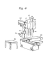
- Fig. 4 is a schematic perspective view of the maching center with the robot device of the present invention illustrated in Figs. 1 to 3, illustrating positional relations between the machine body 10, the robot device 30, the tool storing magazine 60 and the workpiece supplying table 80 in three dimensions.
- the manipulating hand 34 of the robot device 30 is adapted to rotate along the given trajectory A in the embodiment as described above, the robot arm 32 of the robot device 30 may be formed contractible in its axial direction.
- the movement of the manipulating hand 34 is not restricted to the trajectory A so that the position of the workpiece supplying table 80 installed on the floor may be selected very freely, while keeping the advantage that the robot device can be supported rigidly, utilizing the rigidity of the machine body as in the embodiments illustrated.
Landscapes
- Engineering & Computer Science (AREA)
- Mechanical Engineering (AREA)
- Manipulator (AREA)
- Feeding Of Workpieces (AREA)
- Automatic Tool Replacement In Machine Tools (AREA)
Applications Claiming Priority (2)
| Application Number | Priority Date | Filing Date | Title |
|---|---|---|---|
| JP14380479A JPS5669056A (en) | 1979-11-08 | 1979-11-08 | Robot-equipped machining center |
| JP143804/79 | 1979-11-08 |
Publications (3)
| Publication Number | Publication Date |
|---|---|
| EP0028735A2 true EP0028735A2 (fr) | 1981-05-20 |
| EP0028735A3 EP0028735A3 (en) | 1982-02-24 |
| EP0028735B1 EP0028735B1 (fr) | 1984-06-20 |
Family
ID=15347359
Family Applications (1)
| Application Number | Title | Priority Date | Filing Date |
|---|---|---|---|
| EP80106430A Expired EP0028735B1 (fr) | 1979-11-08 | 1980-10-22 | Centre d'usinage équipé d'un robot |
Country Status (4)
| Country | Link |
|---|---|
| US (1) | US4359815A (fr) |
| EP (1) | EP0028735B1 (fr) |
| JP (1) | JPS5669056A (fr) |
| DE (1) | DE3068317D1 (fr) |
Cited By (17)
| Publication number | Priority date | Publication date | Assignee | Title |
|---|---|---|---|---|
| US4359815A (en) * | 1979-11-08 | 1982-11-23 | Fujitsu Fanuc Limited | Machining center with a robot |
| EP0088644A1 (fr) * | 1982-03-10 | 1983-09-14 | Renishaw plc | Machine-outil |
| GB2128909A (en) * | 1982-09-01 | 1984-05-10 | Posalux Sa | Automatic machine tool changing system |
| DE3243335A1 (de) * | 1982-11-19 | 1984-05-24 | Deutsche Industrieanlagen GmbH, 1000 Berlin | Flexible fertigungszelle |
| EP0126272A1 (fr) * | 1983-05-20 | 1984-11-28 | International Business Machines Corporation | Magasin pour matériaux et/ou outils pour robot ou applications analogues |
| EP0174799A3 (en) * | 1984-09-04 | 1987-02-25 | Cincinnati Milacron-Heald Corporation | Machine tools, in particular grinding machines with apparatus for changing grinding wheel tools and workpieces |
| EP0215208A3 (en) * | 1982-03-10 | 1988-08-10 | Renishaw Plc | Machine tool |
| DE3731280A1 (de) * | 1987-09-17 | 1989-03-30 | Maho Ag | Werkzeugwechsler fuer universal-fraes- und bohrmaschinen |
| EP0358928A3 (fr) * | 1988-09-13 | 1991-09-25 | Arnold Müller GmbH & Co. KG | Machine-outil |
| US5068958A (en) * | 1990-09-18 | 1991-12-03 | Dynamotion Corporation | Method and apparatus for changing tools in an automated machine tool |
| EP0516597A1 (fr) * | 1991-05-31 | 1992-12-02 | MIKRON S.p.A. BOLOGNA | Dispositif pour le changement automatique des pièces et de l'outil dans une machine à tailler de roues dentées |
| US5669866A (en) * | 1996-06-10 | 1997-09-23 | W. A. Whitney Co. | Punch press with tool changer |
| US6415339B1 (en) | 1990-04-18 | 2002-07-02 | Rambus Inc. | Memory device having a plurality of programmable internal registers and a delay time register |
| EP2992995A1 (fr) * | 2014-09-08 | 2016-03-09 | DMG Mori Co., Ltd. | Changeur d'outil automatique et machine-outil |
| CN110732906A (zh) * | 2018-07-18 | 2020-01-31 | 友嘉实业股份有限公司 | 模组化智慧刀具交换方法与管理系统 |
| CN111482841A (zh) * | 2019-01-28 | 2020-08-04 | 大隈株式会社 | 机床 |
| EP4292729A1 (fr) * | 2022-06-15 | 2023-12-20 | Progress Maschinen & Automation AG | Procédé de changement automatique d'au moins une matrice de cintrage et/ou d'au moins une buse de guidage d'une machine à cintrer |
Families Citing this family (58)
| Publication number | Priority date | Publication date | Assignee | Title |
|---|---|---|---|---|
| JPS62168766A (ja) * | 1986-01-22 | 1987-07-25 | Mazda Motor Corp | 車体組立装置 |
| DE3138484A1 (de) * | 1981-09-28 | 1983-04-14 | Deutsche Gesellschaft für Wiederaufarbeitung von Kernbrennstoffen mbH, 3000 Hannover | "verfahren zur instandhaltung von vorrichtungen und bauteilen in heissen zellen, insbesondere von wiederaufarbeitungsanlagen fuer abgebrannte kernbrennstoffe, und vorrichtung zur durchfuehrung des verfahrens |
| US4577284A (en) * | 1982-03-31 | 1986-03-18 | International Business Machines Corporation | Adaptive robot batch assembly system |
| US4711016A (en) * | 1982-11-19 | 1987-12-08 | Werner And Kolb Werkzeugmaschinen Gmbh | Flexible manufacturing unit |
| DE3320762C2 (de) * | 1983-06-09 | 1994-10-27 | Trumpf Gmbh & Co | Stanzmaschine mit einem stationären Magazin |
| GB8327437D0 (en) * | 1983-10-13 | 1983-11-16 | British Aerospace | Machine tools |
| WO1985003405A1 (fr) * | 1984-01-23 | 1985-08-01 | Dyna/Pert - Precima Limited | Tete de prehension pour la manipulation de composants electriques |
| JPS60201806A (ja) * | 1984-03-24 | 1985-10-12 | Hitachi Seiki Co Ltd | ワ−ク及びチヤツク爪自動交換用ロボツト付νc旋盤 |
| JPS6176250A (ja) * | 1984-09-24 | 1986-04-18 | Toyoda Mach Works Ltd | ロボツトによる交換システム |
| DE3441590A1 (de) * | 1984-11-14 | 1986-05-22 | Maschinenfabrik Goebel Gmbh, 6100 Darmstadt | Einrichtung zum zufuehren von werkstuecken |
| US4612697A (en) * | 1984-12-14 | 1986-09-23 | Mcdonnell Douglas Corporation | Automated machining system having a workpiece transfer apparatus |
| JPS61149334A (ja) * | 1984-12-25 | 1986-07-08 | Fanuc Ltd | 射出成形機用金型自動交換機 |
| DE3506314A1 (de) * | 1985-02-22 | 1986-08-28 | Kuka Schweissanlagen + Roboter Gmbh, 8900 Augsburg | Verfahren und vorrichtung zum automatischen fuegen und bearbeiten |
| DE8526544U1 (de) * | 1985-09-17 | 1987-04-23 | Chiron-Werke Gmbh, 7200 Tuttlingen | Werkzeugmaschine |
| US4636608A (en) * | 1985-11-15 | 1987-01-13 | Benteler Corporation | Laser contour cut door beams |
| US4644128A (en) * | 1986-01-21 | 1987-02-17 | Benteler Corporation | Laser contour cut manifolds |
| US4886412A (en) * | 1986-10-28 | 1989-12-12 | Tetron, Inc. | Method and system for loading wafers |
| JPS63229240A (ja) * | 1987-03-17 | 1988-09-26 | Kitamura Mach Co Ltd | パレツトチエンジヤ |
| DE3742096A1 (de) * | 1987-12-11 | 1989-06-22 | Wanderer Maschinen Gmbh | Werkzeugmagazin |
| JPH02185350A (ja) * | 1989-01-12 | 1990-07-19 | Mitsubishi Electric Corp | ワーク加工装置 |
| JP3249553B2 (ja) * | 1991-10-18 | 2002-01-21 | ブラザー工業株式会社 | ロボットを用いた扉開閉制御装置 |
| US5309368A (en) * | 1992-01-21 | 1994-05-03 | Chern Shyi Tsae | Workpiece handling mechanism of a C-N-C lathe machine |
| US5318496A (en) * | 1993-04-19 | 1994-06-07 | Amada Engineering And Service Co., Inc. | Method and apparatus for automatically exchanging a punch for a turret punch press |
| US5697520A (en) * | 1993-08-12 | 1997-12-16 | Gerber Scientific Products, Inc. | Mosaic tile maker |
| US5443680A (en) * | 1993-08-12 | 1995-08-22 | Gerber Scientific Products, Inc. | Mosaic tile maker |
| US5509191A (en) * | 1994-01-26 | 1996-04-23 | Best; Norman D. | Apparatus for assembling and processing small parts using a robot |
| SE511704C2 (sv) * | 1998-03-19 | 1999-11-08 | Saab Ab | Förfarande och anordning för montering av vinge |
| FR2781172B1 (fr) * | 1998-07-20 | 2000-10-06 | Renault Automation | Machine-outil notamment de fraisage a structure fermee et disposition ergonomique des parties fonctionnelles d'une telle machine-outil |
| DE20000417U1 (de) * | 2000-01-12 | 2000-05-04 | KHS Maschinen- und Anlagenbau AG, 44143 Dortmund | Magazinvorrichtung für an umlaufenden Behälterbehandlungsmaschinen anbringbaren Bauteilen |
| US6494821B1 (en) * | 2000-08-31 | 2002-12-17 | Hurco Companies, Inc. | Movable arm activated tool changer for machine tool system |
| US6641511B2 (en) | 2000-08-31 | 2003-11-04 | Hurco Companies, Inc. | Movable arm activated tool changer for machine tool system |
| JP2005349762A (ja) * | 2004-06-11 | 2005-12-22 | Fanuc Ltd | 成形品取出装置 |
| US7249992B2 (en) * | 2004-07-02 | 2007-07-31 | Strasbaugh | Method, apparatus and system for use in processing wafers |
| US7774928B2 (en) * | 2004-12-13 | 2010-08-17 | Hirotec America, Inc. | Robotic pallet drive arrangement in a robotic roller hemming system |
| DE102006003985A1 (de) * | 2006-01-20 | 2007-07-26 | Index-Werke Gmbh & Co. Kg Hahn & Tessky | Werkzeugmaschine |
| US7972252B1 (en) * | 2006-03-28 | 2011-07-05 | Honda Motor Co., Ltd. | Ergonomic tool lifting machine and method |
| US20070283780A1 (en) * | 2006-05-02 | 2007-12-13 | Ed Smock | Automated Device and Method for Manufacturing a Door |
| US7713183B2 (en) * | 2006-05-08 | 2010-05-11 | Utica Enterprises, Inc. | Method and apparatus for storing robotic tooling for vehicle body sheet metal robotic assembly |
| EP1894649A1 (fr) * | 2006-09-01 | 2008-03-05 | Stopinc Aktiengesellschaft | Dispositif de maintenance d'un obturateur coulissant monté au trou d'un récipient contenant du métal liquide |
| JP5539012B2 (ja) * | 2010-05-17 | 2014-07-02 | 東芝機械株式会社 | 精密ロール旋盤の自動工具交換装置 |
| AT509708B1 (de) * | 2010-09-02 | 2011-11-15 | Trumpf Maschinen Austria Gmbh | Werkzeugmagazin für einen manipulator |
| DE102012005736A1 (de) | 2012-03-23 | 2013-09-26 | Aberle GmbH | Roboterhandhabungssystem |
| US20140033886A1 (en) * | 2012-08-01 | 2014-02-06 | Xerox Corporation | Document Production System and Method With Automated Die Exchange |
| CH708284B1 (de) | 2013-07-11 | 2023-11-15 | Refractory Intellectual Property Gmbh & Co Kg | Verfahren und Wechselvorrichtung zum automatischen Auswechseln einer Ausgusshülse eines Schiebeverschlusses an einem metallurgischen Gefäss. |
| JP6356014B2 (ja) * | 2014-08-27 | 2018-07-11 | 三菱重工工作機械株式会社 | 歯車加工機械 |
| CN106142081B (zh) * | 2015-05-14 | 2021-03-02 | 发那科株式会社 | 对加工工具转速和工件进给速度进行调整的加工系统 |
| JP6363589B2 (ja) * | 2015-12-24 | 2018-07-25 | ファナック株式会社 | ロボットを備えたワイヤ放電加工システム |
| CN105563198B (zh) * | 2016-03-16 | 2017-10-20 | 吉林大学 | 一种集成式可移动圆盘式刀库及机械手综合性能检测装置 |
| JP6735149B2 (ja) * | 2016-05-11 | 2020-08-05 | オークマ株式会社 | 工作機械 |
| JP6735148B2 (ja) * | 2016-05-11 | 2020-08-05 | オークマ株式会社 | 工作機械 |
| KR20190080877A (ko) | 2016-10-05 | 2019-07-08 | 가부시키가이샤 뉴트리션 액트 | 유기 셀레늄 화합물 함유 조성물 |
| CN106392731B (zh) * | 2016-12-13 | 2018-06-15 | 吉林大学 | 一种圆盘式机械手刀库卡刀掉刀故障预警装置 |
| JP2019010698A (ja) * | 2017-06-29 | 2019-01-24 | オークマ株式会社 | 工作機械 |
| DE102017219407A1 (de) * | 2017-10-27 | 2019-05-02 | Robert Bosch Gmbh | Erfassungsvorrichtung |
| JP6640816B2 (ja) * | 2017-11-01 | 2020-02-05 | ファナック株式会社 | 加工システム |
| JP7188880B2 (ja) * | 2017-12-05 | 2022-12-13 | オークマ株式会社 | 工作機械 |
| US11351643B2 (en) | 2018-02-21 | 2022-06-07 | Navarro IP, LLC | Universal machining apparatus and control system |
| US11163295B2 (en) | 2018-11-21 | 2021-11-02 | Fanuc America Corporation | Continuous machining with robotic table tracking of fixture |
Family Cites Families (11)
| Publication number | Priority date | Publication date | Assignee | Title |
|---|---|---|---|---|
| US3339273A (en) * | 1963-02-11 | 1967-09-05 | Fosdick Machine Tool Co | Automatic tool changing apparatus for machine tools |
| US3312370A (en) * | 1964-05-11 | 1967-04-04 | Scully Anthony Corp | Automatic tool changing apparatus |
| US3550487A (en) * | 1969-07-17 | 1970-12-29 | Kearney & Trecker Corp | Machine tool |
| GB1283584A (en) * | 1969-07-22 | 1972-07-26 | Werkzeugmasch Heckert Veb | Tool changing arrangement for machine tools |
| US4065988A (en) * | 1972-12-04 | 1978-01-03 | Kearney & Trecker Corporation | Unitary work changer for a machining center |
| JPS5410968B2 (fr) * | 1973-05-17 | 1979-05-11 | ||
| DE2651096A1 (de) * | 1976-11-09 | 1978-05-18 | Heyligenstaedt & Co | Werkzeugwechseleinrichtung an drehmaschinen |
| DE2737225A1 (de) * | 1977-08-18 | 1979-02-22 | Heyligenstaedt & Co | Werkzeugmaschine mit einem revolverkopf zur aufnahme von werkzeugen |
| GB2008991B (en) * | 1977-09-27 | 1982-01-20 | Skf Uk Ltd | Method and apparatus for machine tool |
| DD137901A1 (de) * | 1978-07-25 | 1979-10-03 | Dieter Schellenberger | Gestelleinheit fuer handhabungsgeraete |
| JPS5669056A (en) * | 1979-11-08 | 1981-06-10 | Fanuc Ltd | Robot-equipped machining center |
-
1979
- 1979-11-08 JP JP14380479A patent/JPS5669056A/ja active Pending
-
1980
- 1980-10-22 DE DE8080106430T patent/DE3068317D1/de not_active Expired
- 1980-10-22 EP EP80106430A patent/EP0028735B1/fr not_active Expired
- 1980-11-10 US US06/205,157 patent/US4359815A/en not_active Expired - Lifetime
Cited By (22)
| Publication number | Priority date | Publication date | Assignee | Title |
|---|---|---|---|---|
| US4359815A (en) * | 1979-11-08 | 1982-11-23 | Fujitsu Fanuc Limited | Machining center with a robot |
| EP0088644A1 (fr) * | 1982-03-10 | 1983-09-14 | Renishaw plc | Machine-outil |
| WO1983003070A1 (fr) * | 1982-03-10 | 1983-09-15 | Mcmurtry, David, Roberts | Machine-outil |
| US4646422A (en) * | 1982-03-10 | 1987-03-03 | Renishaw Plc | Machine tool |
| EP0215208A3 (en) * | 1982-03-10 | 1988-08-10 | Renishaw Plc | Machine tool |
| GB2128909A (en) * | 1982-09-01 | 1984-05-10 | Posalux Sa | Automatic machine tool changing system |
| DE3243335A1 (de) * | 1982-11-19 | 1984-05-24 | Deutsche Industrieanlagen GmbH, 1000 Berlin | Flexible fertigungszelle |
| EP0126272A1 (fr) * | 1983-05-20 | 1984-11-28 | International Business Machines Corporation | Magasin pour matériaux et/ou outils pour robot ou applications analogues |
| EP0174799A3 (en) * | 1984-09-04 | 1987-02-25 | Cincinnati Milacron-Heald Corporation | Machine tools, in particular grinding machines with apparatus for changing grinding wheel tools and workpieces |
| US4837919A (en) * | 1987-09-17 | 1989-06-13 | Maho Aktiengesellschaft | Tool changing assembly for universal milling and drilling machines |
| DE3731280A1 (de) * | 1987-09-17 | 1989-03-30 | Maho Ag | Werkzeugwechsler fuer universal-fraes- und bohrmaschinen |
| EP0358928A3 (fr) * | 1988-09-13 | 1991-09-25 | Arnold Müller GmbH & Co. KG | Machine-outil |
| US6415339B1 (en) | 1990-04-18 | 2002-07-02 | Rambus Inc. | Memory device having a plurality of programmable internal registers and a delay time register |
| US5068958A (en) * | 1990-09-18 | 1991-12-03 | Dynamotion Corporation | Method and apparatus for changing tools in an automated machine tool |
| EP0516597A1 (fr) * | 1991-05-31 | 1992-12-02 | MIKRON S.p.A. BOLOGNA | Dispositif pour le changement automatique des pièces et de l'outil dans une machine à tailler de roues dentées |
| US5213559A (en) * | 1991-05-31 | 1993-05-25 | Mikron S.P.A. Bologna | Apparatus for changing blanks and tool automatically in a gear cutting machine |
| US5669866A (en) * | 1996-06-10 | 1997-09-23 | W. A. Whitney Co. | Punch press with tool changer |
| EP2992995A1 (fr) * | 2014-09-08 | 2016-03-09 | DMG Mori Co., Ltd. | Changeur d'outil automatique et machine-outil |
| US9902034B2 (en) | 2014-09-08 | 2018-02-27 | Dmg Mori Co., Ltd. | Automatic tool changer and machine tool |
| CN110732906A (zh) * | 2018-07-18 | 2020-01-31 | 友嘉实业股份有限公司 | 模组化智慧刀具交换方法与管理系统 |
| CN111482841A (zh) * | 2019-01-28 | 2020-08-04 | 大隈株式会社 | 机床 |
| EP4292729A1 (fr) * | 2022-06-15 | 2023-12-20 | Progress Maschinen & Automation AG | Procédé de changement automatique d'au moins une matrice de cintrage et/ou d'au moins une buse de guidage d'une machine à cintrer |
Also Published As
| Publication number | Publication date |
|---|---|
| EP0028735B1 (fr) | 1984-06-20 |
| US4359815A (en) | 1982-11-23 |
| JPS5669056A (en) | 1981-06-10 |
| DE3068317D1 (en) | 1984-07-26 |
| EP0028735A3 (en) | 1982-02-24 |
Similar Documents
| Publication | Publication Date | Title |
|---|---|---|
| US4359815A (en) | Machining center with a robot | |
| JP4340739B2 (ja) | 工作機械のパレット交換装置および工作機械 | |
| US8690499B2 (en) | Machine tool | |
| EP1982793A1 (fr) | Tête universelle et machine outil disposant de cette tête universelle | |
| JPS6232063B2 (fr) | ||
| JPH0585300B2 (fr) | ||
| KR20260002626A (ko) | 수평형 가공 공작 기계 | |
| JP6209568B2 (ja) | 工作機械 | |
| JPH04283037A (ja) | 工作機械 | |
| US4797991A (en) | Vertical machining center | |
| US12551951B2 (en) | Combined working machine | |
| KR830002271B1 (ko) | 로봇 장치를 구비한 기계가공 센타 | |
| JP3425907B2 (ja) | 主軸移動型立形工作機械 | |
| JP3573289B2 (ja) | ガンドリル機械 | |
| RU72892U1 (ru) | Станок многоцелевой сверлильно-фрезерно-расточный с возможностью производства шлифовальных работ, с числовым программным управлением и автоматической сменой инструмента | |
| JPH0620706B2 (ja) | パレット交換方法 | |
| KR20230162480A (ko) | 암리스 자동공구교환장치 | |
| JPS5816980B2 (ja) | 金属加工機械 | |
| JPS632270Y2 (fr) | ||
| JP7772921B2 (ja) | 工作機械 | |
| JP5219604B2 (ja) | 工作機械のパレット交換装置 | |
| JPS5816961B2 (ja) | 工作機械 | |
| KR20110067860A (ko) | 버티컬 터닝 센터의 스트래들 툴 | |
| CN119141261A (zh) | 一种复合式多轴数控加工中心 | |
| RU21036U1 (ru) | Станок многоцелевой сверлильно-фрезерно-расточный с числовым программным управлением, с двухпозиционной шпиндельной бабкой, с автоматической сменой инструмента |
Legal Events
| Date | Code | Title | Description |
|---|---|---|---|
| PUAI | Public reference made under article 153(3) epc to a published international application that has entered the european phase |
Free format text: ORIGINAL CODE: 0009012 |
|
| 17P | Request for examination filed |
Effective date: 19801022 |
|
| AK | Designated contracting states |
Designated state(s): DE FR GB |
|
| PUAL | Search report despatched |
Free format text: ORIGINAL CODE: 0009013 |
|
| AK | Designated contracting states |
Designated state(s): DE FR GB |
|
| RAP1 | Party data changed (applicant data changed or rights of an application transferred) |
Owner name: FANUC LIMITED |
|
| GRAA | (expected) grant |
Free format text: ORIGINAL CODE: 0009210 |
|
| AK | Designated contracting states |
Designated state(s): DE FR GB |
|
| REF | Corresponds to: |
Ref document number: 3068317 Country of ref document: DE Date of ref document: 19840726 |
|
| PGFP | Annual fee paid to national office [announced via postgrant information from national office to epo] |
Ref country code: FR Payment date: 19840907 Year of fee payment: 5 |
|
| ET | Fr: translation filed | ||
| PGFP | Annual fee paid to national office [announced via postgrant information from national office to epo] |
Ref country code: DE Payment date: 19841105 Year of fee payment: 5 |
|
| PLBE | No opposition filed within time limit |
Free format text: ORIGINAL CODE: 0009261 |
|
| STAA | Information on the status of an ep patent application or granted ep patent |
Free format text: STATUS: NO OPPOSITION FILED WITHIN TIME LIMIT |
|
| 26N | No opposition filed | ||
| GBPC | Gb: european patent ceased through non-payment of renewal fee | ||
| PG25 | Lapsed in a contracting state [announced via postgrant information from national office to epo] |
Ref country code: FR Free format text: LAPSE BECAUSE OF NON-PAYMENT OF DUE FEES Effective date: 19880630 |
|
| PG25 | Lapsed in a contracting state [announced via postgrant information from national office to epo] |
Ref country code: DE Effective date: 19880701 |
|
| REG | Reference to a national code |
Ref country code: FR Ref legal event code: ST |
|
| PG25 | Lapsed in a contracting state [announced via postgrant information from national office to epo] |
Ref country code: GB Effective date: 19881118 |