EP0028982A2 - Platte zum Auffangen der Sonnenenergie und Anlage, die diese Anwendung umfasst - Google Patents
Platte zum Auffangen der Sonnenenergie und Anlage, die diese Anwendung umfasst Download PDFInfo
- Publication number
- EP0028982A2 EP0028982A2 EP80401593A EP80401593A EP0028982A2 EP 0028982 A2 EP0028982 A2 EP 0028982A2 EP 80401593 A EP80401593 A EP 80401593A EP 80401593 A EP80401593 A EP 80401593A EP 0028982 A2 EP0028982 A2 EP 0028982A2
- Authority
- EP
- European Patent Office
- Prior art keywords
- panel
- panels
- edge
- tube
- tubular
- Prior art date
- Legal status (The legal status is an assumption and is not a legal conclusion. Google has not performed a legal analysis and makes no representation as to the accuracy of the status listed.)
- Granted
Links
- 238000009434 installation Methods 0.000 title claims description 16
- 238000010101 extrusion blow moulding Methods 0.000 claims abstract description 4
- 238000010438 heat treatment Methods 0.000 claims description 8
- 210000000078 claw Anatomy 0.000 claims description 5
- 239000007788 liquid Substances 0.000 claims description 5
- 238000004873 anchoring Methods 0.000 claims description 3
- 239000000463 material Substances 0.000 claims description 3
- 230000000717 retained effect Effects 0.000 claims description 3
- 238000007789 sealing Methods 0.000 claims description 3
- 239000004033 plastic Substances 0.000 claims description 2
- 229920003023 plastic Polymers 0.000 claims description 2
- 229920001903 high density polyethylene Polymers 0.000 abstract description 4
- 239000004700 high-density polyethylene Substances 0.000 abstract description 4
- 238000000034 method Methods 0.000 description 6
- 230000009182 swimming Effects 0.000 description 5
- XLYOFNOQVPJJNP-UHFFFAOYSA-N water Substances O XLYOFNOQVPJJNP-UHFFFAOYSA-N 0.000 description 5
- 238000007664 blowing Methods 0.000 description 4
- 238000004026 adhesive bonding Methods 0.000 description 3
- 238000003466 welding Methods 0.000 description 3
- 238000010276 construction Methods 0.000 description 2
- 238000004519 manufacturing process Methods 0.000 description 2
- 210000002105 tongue Anatomy 0.000 description 2
- 241000218652 Larix Species 0.000 description 1
- 235000005590 Larix decidua Nutrition 0.000 description 1
- 239000000470 constituent Substances 0.000 description 1
- 230000000694 effects Effects 0.000 description 1
- 239000011521 glass Substances 0.000 description 1
- 238000003780 insertion Methods 0.000 description 1
- 230000037431 insertion Effects 0.000 description 1
- 238000009413 insulation Methods 0.000 description 1
- 230000001788 irregular Effects 0.000 description 1
- 238000005304 joining Methods 0.000 description 1
- 238000000465 moulding Methods 0.000 description 1
- 239000012815 thermoplastic material Substances 0.000 description 1
Images


Classifications
-
- F—MECHANICAL ENGINEERING; LIGHTING; HEATING; WEAPONS; BLASTING
- F24—HEATING; RANGES; VENTILATING
- F24S—SOLAR HEAT COLLECTORS; SOLAR HEAT SYSTEMS
- F24S25/00—Arrangement of stationary mountings or supports for solar heat collector modules
- F24S25/60—Fixation means, e.g. fasteners, specially adapted for supporting solar heat collector modules
- F24S25/61—Fixation means, e.g. fasteners, specially adapted for supporting solar heat collector modules for fixing to the ground or to building structures
- F24S25/617—Elements driven into the ground, e.g. anchor-piles; Foundations for supporting elements; Connectors for connecting supporting structures to the ground or to flat horizontal surfaces
-
- F—MECHANICAL ENGINEERING; LIGHTING; HEATING; WEAPONS; BLASTING
- F24—HEATING; RANGES; VENTILATING
- F24S—SOLAR HEAT COLLECTORS; SOLAR HEAT SYSTEMS
- F24S10/00—Solar heat collectors using working fluids
- F24S10/70—Solar heat collectors using working fluids the working fluids being conveyed through tubular absorbing conduits
- F24S10/72—Solar heat collectors using working fluids the working fluids being conveyed through tubular absorbing conduits the tubular conduits being integrated in a block; the tubular conduits touching each other
-
- F—MECHANICAL ENGINEERING; LIGHTING; HEATING; WEAPONS; BLASTING
- F24—HEATING; RANGES; VENTILATING
- F24S—SOLAR HEAT COLLECTORS; SOLAR HEAT SYSTEMS
- F24S10/00—Solar heat collectors using working fluids
- F24S10/70—Solar heat collectors using working fluids the working fluids being conveyed through tubular absorbing conduits
- F24S10/73—Solar heat collectors using working fluids the working fluids being conveyed through tubular absorbing conduits the tubular conduits being of plastic material
-
- F—MECHANICAL ENGINEERING; LIGHTING; HEATING; WEAPONS; BLASTING
- F24—HEATING; RANGES; VENTILATING
- F24S—SOLAR HEAT COLLECTORS; SOLAR HEAT SYSTEMS
- F24S25/00—Arrangement of stationary mountings or supports for solar heat collector modules
- F24S25/10—Arrangement of stationary mountings or supports for solar heat collector modules extending in directions away from a supporting surface
-
- F—MECHANICAL ENGINEERING; LIGHTING; HEATING; WEAPONS; BLASTING
- F24—HEATING; RANGES; VENTILATING
- F24S—SOLAR HEAT COLLECTORS; SOLAR HEAT SYSTEMS
- F24S25/00—Arrangement of stationary mountings or supports for solar heat collector modules
- F24S25/60—Fixation means, e.g. fasteners, specially adapted for supporting solar heat collector modules
- F24S25/65—Fixation means, e.g. fasteners, specially adapted for supporting solar heat collector modules for coupling adjacent supporting elements, e.g. for connecting profiles together
-
- F—MECHANICAL ENGINEERING; LIGHTING; HEATING; WEAPONS; BLASTING
- F24—HEATING; RANGES; VENTILATING
- F24S—SOLAR HEAT COLLECTORS; SOLAR HEAT SYSTEMS
- F24S80/00—Details, accessories or component parts of solar heat collectors not provided for in groups F24S10/00-F24S70/00
- F24S80/30—Arrangements for connecting the fluid circuits of solar collectors with each other or with other components, e.g. pipe connections; Fluid distributing means, e.g. headers
-
- F—MECHANICAL ENGINEERING; LIGHTING; HEATING; WEAPONS; BLASTING
- F24—HEATING; RANGES; VENTILATING
- F24S—SOLAR HEAT COLLECTORS; SOLAR HEAT SYSTEMS
- F24S25/00—Arrangement of stationary mountings or supports for solar heat collector modules
- F24S2025/80—Special profiles
- F24S2025/802—Special profiles having circular or oval cross-section
-
- Y—GENERAL TAGGING OF NEW TECHNOLOGICAL DEVELOPMENTS; GENERAL TAGGING OF CROSS-SECTIONAL TECHNOLOGIES SPANNING OVER SEVERAL SECTIONS OF THE IPC; TECHNICAL SUBJECTS COVERED BY FORMER USPC CROSS-REFERENCE ART COLLECTIONS [XRACs] AND DIGESTS
- Y02—TECHNOLOGIES OR APPLICATIONS FOR MITIGATION OR ADAPTATION AGAINST CLIMATE CHANGE
- Y02E—REDUCTION OF GREENHOUSE GAS [GHG] EMISSIONS, RELATED TO ENERGY GENERATION, TRANSMISSION OR DISTRIBUTION
- Y02E10/00—Energy generation through renewable energy sources
- Y02E10/40—Solar thermal energy, e.g. solar towers
- Y02E10/44—Heat exchange systems
-
- Y—GENERAL TAGGING OF NEW TECHNOLOGICAL DEVELOPMENTS; GENERAL TAGGING OF CROSS-SECTIONAL TECHNOLOGIES SPANNING OVER SEVERAL SECTIONS OF THE IPC; TECHNICAL SUBJECTS COVERED BY FORMER USPC CROSS-REFERENCE ART COLLECTIONS [XRACs] AND DIGESTS
- Y02—TECHNOLOGIES OR APPLICATIONS FOR MITIGATION OR ADAPTATION AGAINST CLIMATE CHANGE
- Y02E—REDUCTION OF GREENHOUSE GAS [GHG] EMISSIONS, RELATED TO ENERGY GENERATION, TRANSMISSION OR DISTRIBUTION
- Y02E10/00—Energy generation through renewable energy sources
- Y02E10/40—Solar thermal energy, e.g. solar towers
- Y02E10/47—Mountings or tracking
Definitions
- the invention a. for object a panel, of generally rectangular shape, made of plastic molded by extrusion blow molding for the capture of solar energy, in which are formed a coil for the circulation of a liquid to be heated, as well as two tubular elements adjacent to two opposite edges of the panel, connected to the respective ends of the coil for the inlet and outlet of the liquid, one of the tubular elements constituting a collector section whose ends are adapted to be able to be tightly connected to the collector sections of two adjacent identical panels arranged laterally.
- the panel of the type mentioned known from patent FR 2 385 067 does not meet the conditions which have just been stated.
- This known panel is provided with a contour frame adapted to receive on one side a greenhouse glass and on the other a thermally insulating layer, for mounting the panel for example on the roof of a house.
- a contour frame adapted to receive on one side a greenhouse glass and on the other a thermally insulating layer, for mounting the panel for example on the roof of a house.
- the object of the invention is therefore to propose a sensor panel of economical construction, usable in the naked state which can be assembled with other panels, without recourse to specialized labor, to constitute a heating installation. water, and whose disassembly can also be carried out very easily.
- the panel according to the invention which is of the type indicated at the start, is characterized in that the tubular element opposite the collector section constitutes a tube which in the plane of the panel is perpendicular to the collector tube and is located in the center of the edge of corresponding panel, and in that this edge comprises on either side of the central pipe means allowing rapid assembly with the corresponding edge of an identical adjacent panel, arranged at the end and oriented at 180 ° relative to the first panel, the hydraulic connection between the two panels being ensured by means of a connection sealingly connecting the adjacent central pipes.
- the adopted party consisting in assembling, preferably by interlocking, two panels to constitute a sensor element, itself designed to be assembled with other juxtaposed elements formed each of the twin panels, while meeting the condition of economy in manufacturing, makes it possible to produce sensor elements whose main dimension, of around 2 m, ensures correct heating of the circulating water and leads to a rational use of the space allocated to a solar heating installation, for example for the equipment of an outdoor swimming pool.
- the panels which are obviously dark in color, for example black or larch green, are light, compact and therefore easy to transport.
- the extrusion-blowing process produces panels practically ready for assembly, in which one of the ends of the collecting tube can receive, during molding, a thread for the screw connection with a flange nut provided at the corresponding end of an adjacent panel.
- the installation of this nut requires only a finishing operation, which is very simple, since it consists in fixing by gluing or welding in the end of the collecting tube a sleeve provided with a beaten collar retaining the flange nut . If necessary, a threaded sleeve can also be provided at the first end.
- the connector ensuring the hydraulic connection between the two panels of a sensor element can itself be fixed by fitting into the two tubes and for this purpose comprise two tubular ends each provided with toric sealing rings.
- the panels can be installed directly on a ground presenting the suitable slope, that this slope preexists or that it is obtained by a profiling of the ground carried out specially.
- a profiling of the ground carried out specially.
- the invention proposes to produce a tubular frame comprising, to support the edges of the elements, parallel tubes uniformly spaced in an inclined plane, assembled at their respective ends with a rail supported high by vertical posts fixed in the ground and with a low beam placed on the ground.
- This arrangement makes it possible to form rectangular meshes in each of which is supported an element formed by the assembly of two panels.
- each panel edge advantageously has a profiled rim in the shape of a quarter cylinder as well as one or more holes through which the one of the branches of a stirrup whose bottom is supported on the adjacent edges of juxtaposed panels and in the folded ends of which can be inserted a removable pin engaged with the underside of the oblique tube underlying the two flanges.
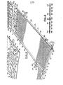
- Figure 1 shows a tubular frame 1 comprising vertical posts 2 fixed in the ground and uniformly spaced in the same plane, which support a horizontal tubular rail 3 with which is assembled the high end 4 of tubes 6, parallel to each other and uniformly spaced in an inclined plane, the lower end 7 of which is itself assembled with a lower tubular arm 8 placed on the ground.
- sensor panels A In the rectangular meshes formed by the tubes 6, 7, 8 are supported sensor panels A, all identical. Two of these panels A 1 and A 2 , assembled end to end by forming a sensor element B are represented in one of the meshes, while in the adjacent mesh only the upper panel laughing A 3 is shown.
- Each post 2 is constituted by a tube whose lower end 9 is fitted in a separable manner in a tubular foot 11 anchored permanently in the ground and is retained by means of a removable pin 12, one of the branches of which is threaded at through the tubular base-11 and through the end 9 of the tube.
- each panel A which has the general shape of a rectangle whose large dimension, equal for example to about 1 m, corresponds to the direction of the support tubes 6, and is made of high density polyethylene (HDPE) molded by the extrusion-blowing process, a coil 13 is formed whose rectilinear waves are parallel to the small dimension of the panel, equal for example to about 0.5 m.
- One end 10 of the coil is connected to a collecting tube 14 extending over the entire width of an edge corresponding to the panel, so that it can be assembled in leaktight manner at its two ends to the collecting tube 14 of two adjacent panels arranged laterally.
- one end, 16, of the collecting tube is provided with a thread 17 molded and its other end 18 receives, after demolding from the panel, a short sleeve fixed by gluing or welding, on which is formed a beaten collar which retains the collar of a nut 19, provided with a crenellation 21 making it possible to carry out by hand, after insertion of a sealing ring, the junction by screwing of the two collecting tubes.
- the other end 22 of the coil 13 is connected, at the center of the opposite edge b of the panel such as A 1 (FIG. 3), to a tube 23, oriented perpendicular to the collecting tube 14, into which one of the end pieces 24 provided with O-ring seals 26 with a connector 27, the other end piece 24 of which can likewise be fitted in a sealed manner in the central pipe 23 of an adjacent panel A2 oriented at 180 ° relative to to panel A 1 and assembled at the end with the latter.
- the edge b of the panels A 1 and A 2 comprises, in addition to a central notch 28 releasing the central tube-23, on one side of the latter, two spaced cutouts 29, 31, oriented longitudinally, which delimit with the central notch 28 and the corresponding edge of the panel three tabs 32, 33, 34, and on the other side of the pipe 23 a shallow groove 36 on either side of which two areas 37, 38 are formed.
- the transverse position and dimension of the notch, the cutouts and the groove are such that the edges b of the panels A 1 , A 2 can interpenetrate by interlocking, the main tongue 33 and the auxiliary tongues 32, 34 of the edge b of one of the panels respectively engaging in the groove 36 and on the top of the pads 37, 38 of the edge b of the 'other panel (Figs. 4 and 5), while simultaneously the fitting 27 initially fitted into the tubing 23 of one of the edges fits into the tubing 23 of the other edge.
- Each edge of a panel A also has a rim 41 whose quarter-cylinder profile is adapted to the shape of the support tube 6, as well as two oblong holes 42 in each of which can be engaged one of the branches 43, of which the end is folded 180 ° at 45, of a stirrup 44, the semi-circular bottom of which bears on the edges 41 of two juxtaposed panels A.
- This stirrup ensures the separable assembly of two panels with the support tube 6 underlying the two flanges, by means of a pin 46 inserted through the folds 45 of the stirrup and of which one of the branches 47, bent at this indeed, engages the underside of the tube 6.
- a similar assembly method is provided for securing the top rail 3 of the tubular frame with the posts 2.
- the underside of the tubular rail 3 is kept in contact with the end section of the post 2 by means of a stirrup 48, the bottom of which follows the cylindrical shape of the heddle 3 and of a pin 49, one of the branches of which is threaded through a fold 51 of the branches of the stirrup, the other branch of the pin being engaged by its camber 52 with the cylindrical surface of the post.
- FIG. 2 also shows the assembly of the upper end 4 of an oblique support tube 6 with the high tubular arm 3.
- the cylindrical part 53 of a flange 54 rigidly encloses the end 4 of the tube 6, thanks to a bolt 56 passing through the two tabs 57 of the flange and a nut 58, and these two tabs extend downward forming two claws 59, 61, of semi-circular shape which are engaged with two opposite faces of the heddle tubular 3.
- An identical flange 54 is used for assembling the lower end 7 of the support tube 6 with the low tubular bar 8 (fig. 1 and 3).
- FIG. 2 finally shows that the end of the rim 21 of a panel A which is adjacent to the collecting tube 14 is provided with a collar 62 forming a stop with respect to the end face of the flange 54 fixed on the rail high 3, which allows precise and immediate positioning on the tubular framework of a sensor element B.
- the panels A 1 , A 2 and A 3 , A 4 forming two juxtaposed solar elements B 1 , B 2 are placed directly on the ground which has an appropriate slope.
- the panels are, with respect to the arrangement of FIGS. 1 and 3, an inverted position, the flanges 41 bearing by their free edge 64 with the ground while maintaining the main surface of the panels slightly raised.
- the inner branch of these pins traver - sant a notch 67 formed in the adjacent area of panels.
- wide pins 68 passing through coincidental openings 69 of the overlap zone of the assembled edges b of the panels of elements B 1 and B 2 are stuck in the ground.
- the end 18 of the collecting tube 14 forms a bellows 72 near the end beat collar 71 which is molded, which makes the corresponding zone of the tube deformable by allowing the latter to absorb thermal expansion and to adapt any misalignment with respect to the collecting tube of an adjacent panel.
Landscapes
- Engineering & Computer Science (AREA)
- Physics & Mathematics (AREA)
- Life Sciences & Earth Sciences (AREA)
- Sustainable Development (AREA)
- Sustainable Energy (AREA)
- Thermal Sciences (AREA)
- Chemical & Material Sciences (AREA)
- Combustion & Propulsion (AREA)
- Mechanical Engineering (AREA)
- General Engineering & Computer Science (AREA)
- Photovoltaic Devices (AREA)
- Heat-Exchange Devices With Radiators And Conduit Assemblies (AREA)
Applications Claiming Priority (2)
| Application Number | Priority Date | Filing Date | Title |
|---|---|---|---|
| FR7927637 | 1979-11-09 | ||
| FR7927637A FR2469670A1 (fr) | 1979-11-09 | 1979-11-09 | Panneau pour le captage de l'energie solaire et installation en comportant application |
Publications (3)
| Publication Number | Publication Date |
|---|---|
| EP0028982A2 true EP0028982A2 (de) | 1981-05-20 |
| EP0028982A3 EP0028982A3 (en) | 1981-11-25 |
| EP0028982B1 EP0028982B1 (de) | 1984-02-15 |
Family
ID=9231470
Family Applications (1)
| Application Number | Title | Priority Date | Filing Date |
|---|---|---|---|
| EP80401593A Expired EP0028982B1 (de) | 1979-11-09 | 1980-11-07 | Platte zum Auffangen der Sonnenenergie und Anlage, die diese Anwendung umfasst |
Country Status (7)
| Country | Link |
|---|---|
| EP (1) | EP0028982B1 (de) |
| AR (1) | AR229580A1 (de) |
| AU (1) | AU6412780A (de) |
| BR (1) | BR8007257A (de) |
| DE (1) | DE3066634D1 (de) |
| ES (1) | ES8205052A1 (de) |
| FR (1) | FR2469670A1 (de) |
Cited By (13)
| Publication number | Priority date | Publication date | Assignee | Title |
|---|---|---|---|---|
| EP0069839A1 (de) * | 1981-07-10 | 1983-01-19 | Hüls Aktiengesellschaft | Verwendung von Hydroxyestergemischen als Verfilmungshilfsmittel für filmbildende, wässrige Kunststoffdispersionen |
| EP0076455A3 (en) * | 1981-10-01 | 1983-08-24 | Joachim Wenzel | Solar plant |
| GB2151012A (en) * | 1983-11-24 | 1985-07-10 | Yoshihiro Yonahara | Apparatus for warming a liquid by solar power |
| FR2566107A1 (fr) * | 1984-06-15 | 1985-12-20 | Rossignol Sa | Panneau pour echangeur de chaleur, echangeur en resultant et applications, notamment aux pompes a chaleur |
| FR2651030A1 (fr) * | 1989-08-21 | 1991-02-22 | Nicot Christian | Dispositif de fixation articule a reglage omnidirectionnel pour panneaux et, en particulier, panneaux solaires ou d'affichage electroniques |
| EP0841523A3 (de) * | 1996-11-07 | 1999-07-07 | Friedrich Udo Müller | Solarabsorber mit Wellrohrabschnitten |
| NL1025699C2 (nl) * | 2004-03-11 | 2005-09-13 | R & R Systems B V | Zonnecollector. |
| FR2869097A1 (fr) * | 2004-04-16 | 2005-10-21 | Alain Vanquaethem | Dispositif de chauffage solaire |
| FR2955924A1 (fr) * | 2010-01-29 | 2011-08-05 | Cobsolaire | Dispositif de production d'energie solaire pour couverture ou avancee de batiment |
| WO2011089114A3 (de) * | 2010-01-20 | 2012-05-03 | Krinner Innovation Gmbh | Fundamentsystem für solarpaneele mit vormontierbaren beschlagteilen |
| DE112009002536T5 (de) | 2008-10-30 | 2012-06-14 | Técnica En Instalaciones de Fluidos, S.L. | Flexibles solarthermisches System zur Produktion von Warmwasser bis zu hohen Temperaturen |
| FR2981738A1 (fr) * | 2011-10-19 | 2013-04-26 | Deversel Nv | Element photovoltaique et/ou thermogene de garde-corps et garde-corps constitues de tels elements |
| WO2013175264A1 (en) * | 2012-05-21 | 2013-11-28 | Pyxis Ltd | A heat exchanger and connector there of |
Family Cites Families (5)
| Publication number | Priority date | Publication date | Assignee | Title |
|---|---|---|---|---|
| US4055163A (en) * | 1975-04-16 | 1977-10-25 | Costello Frederick A | Solar heating system |
| JPS51129947A (en) * | 1975-04-21 | 1976-11-11 | British Petroleum Co | Solar energy collecting apparatus |
| DE2544915A1 (de) * | 1975-10-07 | 1977-04-21 | Arbonia Ag | Sonnenkollektor |
| DE2712387A1 (de) * | 1977-03-22 | 1978-10-05 | Roth Kg Metallwerk | Sonnenkollektor |
| DE2741983C3 (de) * | 1977-09-17 | 1981-10-08 | Helmut 7293 Pfalzgrafenweiler Genkinger | Verfahren zum Herstellen einer Röhren-Absorberbaueinheit, insbesondere für Solarenergie-Nutzungsanlagen |
-
1979
- 1979-11-09 FR FR7927637A patent/FR2469670A1/fr active Granted
-
1980
- 1980-11-06 AU AU64127/80A patent/AU6412780A/en not_active Abandoned
- 1980-11-07 DE DE8080401593T patent/DE3066634D1/de not_active Expired
- 1980-11-07 BR BR8007257A patent/BR8007257A/pt unknown
- 1980-11-07 ES ES497078A patent/ES8205052A1/es not_active Expired
- 1980-11-07 AR AR283164A patent/AR229580A1/es active
- 1980-11-07 EP EP80401593A patent/EP0028982B1/de not_active Expired
Cited By (15)
| Publication number | Priority date | Publication date | Assignee | Title |
|---|---|---|---|---|
| EP0069839A1 (de) * | 1981-07-10 | 1983-01-19 | Hüls Aktiengesellschaft | Verwendung von Hydroxyestergemischen als Verfilmungshilfsmittel für filmbildende, wässrige Kunststoffdispersionen |
| EP0076455A3 (en) * | 1981-10-01 | 1983-08-24 | Joachim Wenzel | Solar plant |
| GB2151012A (en) * | 1983-11-24 | 1985-07-10 | Yoshihiro Yonahara | Apparatus for warming a liquid by solar power |
| FR2566107A1 (fr) * | 1984-06-15 | 1985-12-20 | Rossignol Sa | Panneau pour echangeur de chaleur, echangeur en resultant et applications, notamment aux pompes a chaleur |
| FR2651030A1 (fr) * | 1989-08-21 | 1991-02-22 | Nicot Christian | Dispositif de fixation articule a reglage omnidirectionnel pour panneaux et, en particulier, panneaux solaires ou d'affichage electroniques |
| EP0841523A3 (de) * | 1996-11-07 | 1999-07-07 | Friedrich Udo Müller | Solarabsorber mit Wellrohrabschnitten |
| NL1025699C2 (nl) * | 2004-03-11 | 2005-09-13 | R & R Systems B V | Zonnecollector. |
| EP1574792A3 (de) * | 2004-03-11 | 2005-09-21 | R & R Systems B.V. | Sonnenkollektor |
| FR2869097A1 (fr) * | 2004-04-16 | 2005-10-21 | Alain Vanquaethem | Dispositif de chauffage solaire |
| EP1586828A3 (de) * | 2004-04-16 | 2010-09-15 | Alain Vanquaethem | Solarheizungsvorrichtung |
| DE112009002536T5 (de) | 2008-10-30 | 2012-06-14 | Técnica En Instalaciones de Fluidos, S.L. | Flexibles solarthermisches System zur Produktion von Warmwasser bis zu hohen Temperaturen |
| WO2011089114A3 (de) * | 2010-01-20 | 2012-05-03 | Krinner Innovation Gmbh | Fundamentsystem für solarpaneele mit vormontierbaren beschlagteilen |
| FR2955924A1 (fr) * | 2010-01-29 | 2011-08-05 | Cobsolaire | Dispositif de production d'energie solaire pour couverture ou avancee de batiment |
| FR2981738A1 (fr) * | 2011-10-19 | 2013-04-26 | Deversel Nv | Element photovoltaique et/ou thermogene de garde-corps et garde-corps constitues de tels elements |
| WO2013175264A1 (en) * | 2012-05-21 | 2013-11-28 | Pyxis Ltd | A heat exchanger and connector there of |
Also Published As
| Publication number | Publication date |
|---|---|
| ES497078A0 (es) | 1982-06-01 |
| BR8007257A (pt) | 1981-05-19 |
| DE3066634D1 (en) | 1984-03-22 |
| AR229580A1 (es) | 1983-09-30 |
| ES8205052A1 (es) | 1982-06-01 |
| AU6412780A (en) | 1981-05-14 |
| FR2469670B1 (de) | 1984-01-06 |
| FR2469670A1 (fr) | 1981-05-22 |
| EP0028982B1 (de) | 1984-02-15 |
| EP0028982A3 (en) | 1981-11-25 |
Similar Documents
| Publication | Publication Date | Title |
|---|---|---|
| EP0028982B1 (de) | Platte zum Auffangen der Sonnenenergie und Anlage, die diese Anwendung umfasst | |
| EP0109374A1 (de) | Vorrichtung zum Auffangen von Sonnenenergie auf einem Dach oder ähnlichem | |
| EP0146469B1 (de) | Raumfachwerk aus Beton und Verfahren zur Herstellung des genannten Fachwerkes | |
| FR2469673A1 (fr) | Element de construction formant capteur d'energie solaire | |
| FR2554840A1 (fr) | Terrain de sport, en particulier court ou mini-court de tennis realise a l'aide de panneaux amovibles | |
| EP2245381A1 (de) | Wärmetauschplatte, herstellungsverfahren dafür und vorrichtung zur abdeckung eines gebäudes | |
| FR2793504A1 (fr) | Dalle de plafond | |
| EP1362152A1 (de) | Druckbeständiger und fluiddichter behälter | |
| CA2459929A1 (fr) | Panneaux modulaires pour la realisation de bassin de piscine | |
| FR2666612A1 (fr) | Structure demontable de halls, chapiteaux ou analogues. | |
| FR2533606A1 (fr) | Dispositif pour la constitution d'un joint de dilatation entre deux elements de construction, joint de dilatation obtenu et procede de mise en oeuvre | |
| CA1154929A (fr) | Procede de construction d'une toiture auto-portante, eclisse pour la mise en oeuvre dudit procede et toiture auto-portante correspondante | |
| EP1308584B1 (de) | Zaun mit einer Vielzahl von Pfosten und Drahtpaneelen und Verfahren zu dessen Errichtung | |
| FR2684712A1 (fr) | Dispositif de liaison etanche pour abris legers modulaires. | |
| FR2636718A1 (fr) | Structure en coque et procede de fabrication d'une telle structure | |
| FR2960048A1 (fr) | Paroi formee d'une pluralite de panneaux solaires juxtaposes, comportant des moyens d'isolation thermique, et procede de fabrication d'une telle paroi | |
| EP0146468A2 (de) | Ballast-Betonbodenplatte für Offshore-Plattform | |
| FR2960047A1 (fr) | Dispositif d'etancheite d'une paroi formee d'une pluralite de panneaux solaires juxtaposes | |
| FR2525659A1 (fr) | Element autoportant et de grande longueur pour la realisation d'une toiture de batiment | |
| FR2848233A1 (fr) | Plaque en materiau synthetique notamment plaque de revetement de sol | |
| FR2764915A1 (fr) | Regard prefabrique pour le raccordement et/ou la visite de canalisations d'assainissement, et procede de mise en place d'un tel regard | |
| BE851252A (fr) | Recuperateur d'energie solaire | |
| FR2495755A1 (en) | Coaxial tubes in heat exchanger for hot acid - formed of sections connected by axial tensioning bars | |
| FR2574910A1 (fr) | Capteur solaire amovible formant couverture de piscine | |
| CH547405A (fr) | Construction segmentaire. |
Legal Events
| Date | Code | Title | Description |
|---|---|---|---|
| PUAI | Public reference made under article 153(3) epc to a published international application that has entered the european phase |
Free format text: ORIGINAL CODE: 0009012 |
|
| AK | Designated contracting states |
Designated state(s): BE DE GB IT NL |
|
| PUAL | Search report despatched |
Free format text: ORIGINAL CODE: 0009013 |
|
| AK | Designated contracting states |
Designated state(s): BE DE GB IT NL |
|
| 17P | Request for examination filed |
Effective date: 19820522 |
|
| ITF | It: translation for a ep patent filed | ||
| GRAA | (expected) grant |
Free format text: ORIGINAL CODE: 0009210 |
|
| AK | Designated contracting states |
Designated state(s): BE DE GB IT NL |
|
| PG25 | Lapsed in a contracting state [announced via postgrant information from national office to epo] |
Ref country code: NL Effective date: 19840215 |
|
| REF | Corresponds to: |
Ref document number: 3066634 Country of ref document: DE Date of ref document: 19840322 |
|
| NLV1 | Nl: lapsed or annulled due to failure to fulfill the requirements of art. 29p and 29m of the patents act | ||
| PG25 | Lapsed in a contracting state [announced via postgrant information from national office to epo] |
Ref country code: BE Effective date: 19841130 |
|
| PLBE | No opposition filed within time limit |
Free format text: ORIGINAL CODE: 0009261 |
|
| STAA | Information on the status of an ep patent application or granted ep patent |
Free format text: STATUS: NO OPPOSITION FILED WITHIN TIME LIMIT |
|
| 26N | No opposition filed | ||
| BERE | Be: lapsed |
Owner name: ROSSIGNOL S.A. Effective date: 19841107 |
|
| GBPC | Gb: european patent ceased through non-payment of renewal fee | ||
| PG25 | Lapsed in a contracting state [announced via postgrant information from national office to epo] |
Ref country code: DE Effective date: 19850801 |
|
| PG25 | Lapsed in a contracting state [announced via postgrant information from national office to epo] |
Ref country code: GB Effective date: 19881118 |