EP0028989A1 - Frein à tambour - Google Patents
Frein à tambour Download PDFInfo
- Publication number
- EP0028989A1 EP0028989A1 EP19800401628 EP80401628A EP0028989A1 EP 0028989 A1 EP0028989 A1 EP 0028989A1 EP 19800401628 EP19800401628 EP 19800401628 EP 80401628 A EP80401628 A EP 80401628A EP 0028989 A1 EP0028989 A1 EP 0028989A1
- Authority
- EP
- European Patent Office
- Prior art keywords
- torque plate
- shells
- parts
- drum brake
- drum
- Prior art date
- Legal status (The legal status is an assumption and is not a legal conclusion. Google has not performed a legal analysis and makes no representation as to the accuracy of the status listed.)
- Granted
Links
Images


Classifications
-
- F—MECHANICAL ENGINEERING; LIGHTING; HEATING; WEAPONS; BLASTING
- F16—ENGINEERING ELEMENTS AND UNITS; GENERAL MEASURES FOR PRODUCING AND MAINTAINING EFFECTIVE FUNCTIONING OF MACHINES OR INSTALLATIONS; THERMAL INSULATION IN GENERAL
- F16D—COUPLINGS FOR TRANSMITTING ROTATION; CLUTCHES; BRAKES
- F16D65/00—Parts or details
- F16D65/14—Actuating mechanisms for brakes; Means for initiating operation at a predetermined position
- F16D65/16—Actuating mechanisms for brakes; Means for initiating operation at a predetermined position arranged in or on the brake
- F16D65/22—Actuating mechanisms for brakes; Means for initiating operation at a predetermined position arranged in or on the brake adapted for pressing members apart, e.g. for drum brakes
-
- F—MECHANICAL ENGINEERING; LIGHTING; HEATING; WEAPONS; BLASTING
- F16—ENGINEERING ELEMENTS AND UNITS; GENERAL MEASURES FOR PRODUCING AND MAINTAINING EFFECTIVE FUNCTIONING OF MACHINES OR INSTALLATIONS; THERMAL INSULATION IN GENERAL
- F16D—COUPLINGS FOR TRANSMITTING ROTATION; CLUTCHES; BRAKES
- F16D51/00—Brakes with outwardly-movable braking members co-operating with the inner surface of a drum or the like
- F16D51/16—Brakes with outwardly-movable braking members co-operating with the inner surface of a drum or the like shaped as brake-shoes pivoted on a fixed or nearly-fixed axis
- F16D51/18—Brakes with outwardly-movable braking members co-operating with the inner surface of a drum or the like shaped as brake-shoes pivoted on a fixed or nearly-fixed axis with two brake-shoes
- F16D51/20—Brakes with outwardly-movable braking members co-operating with the inner surface of a drum or the like shaped as brake-shoes pivoted on a fixed or nearly-fixed axis with two brake-shoes extending in opposite directions from their pivots
- F16D51/24—Brakes with outwardly-movable braking members co-operating with the inner surface of a drum or the like shaped as brake-shoes pivoted on a fixed or nearly-fixed axis with two brake-shoes extending in opposite directions from their pivots fluid actuated
-
- F—MECHANICAL ENGINEERING; LIGHTING; HEATING; WEAPONS; BLASTING
- F16—ENGINEERING ELEMENTS AND UNITS; GENERAL MEASURES FOR PRODUCING AND MAINTAINING EFFECTIVE FUNCTIONING OF MACHINES OR INSTALLATIONS; THERMAL INSULATION IN GENERAL
- F16D—COUPLINGS FOR TRANSMITTING ROTATION; CLUTCHES; BRAKES
- F16D51/00—Brakes with outwardly-movable braking members co-operating with the inner surface of a drum or the like
- F16D2051/001—Parts or details of drum brakes
- F16D2051/003—Brake supports
-
- F—MECHANICAL ENGINEERING; LIGHTING; HEATING; WEAPONS; BLASTING
- F16—ENGINEERING ELEMENTS AND UNITS; GENERAL MEASURES FOR PRODUCING AND MAINTAINING EFFECTIVE FUNCTIONING OF MACHINES OR INSTALLATIONS; THERMAL INSULATION IN GENERAL
- F16D—COUPLINGS FOR TRANSMITTING ROTATION; CLUTCHES; BRAKES
- F16D51/00—Brakes with outwardly-movable braking members co-operating with the inner surface of a drum or the like
- F16D2051/001—Parts or details of drum brakes
- F16D2051/005—Protective covers
-
- F—MECHANICAL ENGINEERING; LIGHTING; HEATING; WEAPONS; BLASTING
- F16—ENGINEERING ELEMENTS AND UNITS; GENERAL MEASURES FOR PRODUCING AND MAINTAINING EFFECTIVE FUNCTIONING OF MACHINES OR INSTALLATIONS; THERMAL INSULATION IN GENERAL
- F16D—COUPLINGS FOR TRANSMITTING ROTATION; CLUTCHES; BRAKES
- F16D51/00—Brakes with outwardly-movable braking members co-operating with the inner surface of a drum or the like
Definitions
- the invention relates to a drum brake incorporating a new wheel cylinder and a torque plate construction.
- a wheel cylinder is commonly produced by casting which requires a number of machining operations and is expensive.
- the cylinder is also quite heavy.
- the cylinder is then affixed to a heavy backing plate which is affixed to a rear axle housing of a vehicle.
- the backing plate is usually stamped.
- the invention proposes a drum brake comprising a torque plate for supporting a pair of brake shoes and an hydraulic actuator for urging said pair of brake shoes into frictional engagement with a brake drum, characterized in that said torque plate comprises two stamped torque plate parts, each having a central planar portion to be affixed to the other planar portion and to a wheel axle housing or the like, said torque plate parts having matching shells which form complete shells when said parts are assembled, and a member having a cylindrical bore therethrough mounted in said matching shells to substantially define said hydraulic actuator.
- the present invention provides a wheel cylinder for a drum brake which is made of a plastic cylindrical member molded in a steel shell.
- the steel shell constitutes part of the mold and also backs up the plastic cylindrical member in the pressurized area so that the maximum pressure is not limited by the strength of the plastic material.
- Such a wheel cylinder is lighter in weight and eliminates a number of machining operations.
- the steel shell of the wheel cylinder can be structurally integral with a torque plate.
- the torque plate can be made of two substantially identical parts which can be stamped and then suitably affixed together. Such a construction also is lighter in weight than conventional torque plates and can be used with a thin, lightweight dust or splash shield.
- the two torque plate parts can have semi-cylindrical shells which form the wheel cylinder shell when assembled.
- An advantage of the invention is to provide a wheel cylinder and torque plate construction in which the torque plate is made up of two substantially identical stamped parts.
- a drum brake indicated at 10 is shown for purposes of illustration of the invention and is schematic, with components omitted.
- the brake includes a stationary assembly 12 and a brake drum 14.
- the stationary assembly is suitably affixed by bolts 16 or the like to a stationary portion of a vehicle, such as a flange 18 of a rear axle housing 20.
- the brake drum 14 has an outer cylindrical member 22 with an annular flange 24 and a circular front 26 which is affixed by bolts 28 or the like to a rotating portion of the vehicle, such as a wheel flange 30 of a drive axle 32.
- the specific drum brake design does not constitute part of the invention.
- the stationary assembly 12 includes brake shoes 34 having arcuate portions 36 to which friction linings 38 are affixed.
- the shoes also have inwardly-extending webs 40 which are perpendicular to the arcuate portions and provide rigidity therefor.
- the brake shoes have a suitable adjuster 42 and are connected by springs 44 and 46.
- the brake shoe adjusting sys- tern 42 can be of the type shown in U.S. Patent 3 958 674, for example.
- One of the brake shoes 38 is backed up by an anchor pin 48, depending upon the direction of rotation of the brake drum 14, when the brakes are applied.
- the stationary assembly 12 also includes a torque plate 50 which holds the anchor pin 48 and a wheel cylinder 52 which moves the brake shoes 38 against the cylindrical member 22 of the brake drum 14.
- the torque plate and wheel cylinder are constructed in accordance with the invention.
- the shield 54 has an outer cylindrical flange 56 which extends between the brake drum member 22 and the flange 24 and serves as protection against water, dust, and other contaminants.
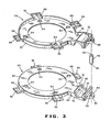
- the torque plate 50 includes a front stamped part 58 and a rear stamped part 60 which are substantially identical and which are affixed together by spot welding or riveting, by way of example.
- the front part 58 has a circular planar portion 62 with spaced bolt holes 64 for the bolts 16 to affix the torque plate to the flange therebetween.
- Several ears 66 are set off from the plane of the circular portion 62, away from the rear part 60, by offsets 68.
- the ears 66 extend along the sides of the brake shoe webs 40 ( Figures 1 and 2) to provide a guide for the expansion of the webs.
- Suitable stiffening flanges 70 extend outwardly from the planar circular portion 62 with U-shaped stiffening flanges 72 being located around the ears 66.
- the front part 58 also has an extension 74 extending radially outwardly and terminating in a semi-cylindrical shell 76.
- the shell has a semi-circular end wall 78 terminating in a short semi-cylindrical web 80.
- a U-shaped stiffening flange 82 extends around the shell 76 with an outer edge terminating in an ear 84 with a hole 86 centrally located therein and an extension flange 88 extending therefrom.
- the hole 86 receives a reduced end 90 of the anchor pin 48 with the reduced end peened over or welded to the ear.
- the rear stamped part 60 of the torque plate 50 is substantially identical to the front stamped part 58 except for two nipples 92 and 94 which extend outwardly from the semi-cylindrical shell 76 thereof. These will be discussed in more detail subsequently.
- the semi-cylindrical shells 76 match to form a complete shell and are placed in a mold or die which extends beyond the ends of the shell and is also provided with a suitable cylindrical core.
- Plastic is then injected into the mold to form a plastic cylindrical member 96 ( Figures 4-6) with a cylindrical inner surface or bor-e 98 and circular end flanges 100 formed by the mold and positioned beyond the stiffening flanges 82 of the shell 76.
- Conventional rubber sealing boots 102 can then be mounted on the flanges 100 to seal the ends of the cylinder 52.
- the boots 102 also cooperate with conventional metal pistons 104 having inner ends engaged by rubber cup seals 106 which are urged outwardly by a spring 108.
- Two substantially tangential passages 112 are formed in the plastic cylindrical member 96 and communicate with the interior thereof, within the surface 98. One of these passages supplies the brake fluid under pressure to the wheel cylinder 52 and the other provides a vent or bleed for bleeding air from the cylinder.
- the passages 112 communicate with threaded recesses 114 formed in the plastic material adjacent openings 116 in the nipples 92 and 94. Suitable fittings can be threaded through the openings 1 16 into the threaded recesses 114 to connect the cylinder with the brake fluid and bleed lines.
- FIG. 6 An alternative nipple arrangement for connecting the wheel cylinder with fittings is shown in Figure 6.
- the shell 76 has flush openings 118 located in generally similar positions to the nipples 92 and 94.
- a threaded connector 120 has a small end inserted through the opening 118 and peened over to provide a mechanical connection between the connector and the shell. This is done prior to molding.
- Suitable passages 122 similar to the passages 112 are then formed in the plastic material after a suitable plug is removed from the threaded connector 120 after the molding operation is complete.
- the wheel cylinder and the torque plate require minimum machining operations as compared to the cast members heretofore employed. Also, the weight'of the wheel cylinder and the torque plate is also substantially less than the cast components heretofore employed. The assembly operation of the drum brake components is also reduced when the wheel cylinder and the torque plate are made as one unit. The symmetrical arrangement of the torque plate in mounting the anchor pin also provides a better distribution of forces from the anchor pin to the axle housing flange.
Landscapes
- Engineering & Computer Science (AREA)
- General Engineering & Computer Science (AREA)
- Mechanical Engineering (AREA)
- Braking Arrangements (AREA)
Applications Claiming Priority (2)
| Application Number | Priority Date | Filing Date | Title |
|---|---|---|---|
| US9336179A | 1979-11-13 | 1979-11-13 | |
| US93361 | 1979-11-13 |
Publications (2)
| Publication Number | Publication Date |
|---|---|
| EP0028989A1 true EP0028989A1 (fr) | 1981-05-20 |
| EP0028989B1 EP0028989B1 (fr) | 1984-07-04 |
Family
ID=22238495
Family Applications (1)
| Application Number | Title | Priority Date | Filing Date |
|---|---|---|---|
| EP19800401628 Expired EP0028989B1 (fr) | 1979-11-13 | 1980-11-13 | Frein à tambour |
Country Status (5)
| Country | Link |
|---|---|
| EP (1) | EP0028989B1 (fr) |
| JP (1) | JPS5683625A (fr) |
| AR (1) | AR222585A1 (fr) |
| AU (1) | AU536661B2 (fr) |
| DE (1) | DE3068457D1 (fr) |
Cited By (1)
| Publication number | Priority date | Publication date | Assignee | Title |
|---|---|---|---|---|
| US6698557B2 (en) * | 2001-09-10 | 2004-03-02 | Arvinmeritor Technology, Llc | Brake drum cooling apparatus |
Citations (10)
| Publication number | Priority date | Publication date | Assignee | Title |
|---|---|---|---|---|
| US1362372A (en) * | 1919-08-11 | 1920-12-14 | Pedro Luis | Vehicle-brake |
| US2247374A (en) * | 1934-08-15 | 1941-07-01 | Hawley Jones Corp | Brake |
| US2257628A (en) * | 1939-04-17 | 1941-09-30 | Nash Kelvinator Corp | Brake |
| GB606342A (en) * | 1944-03-20 | 1948-08-12 | Bendix Aviat Corp | Improvements in or relating to brakes |
| FR1388321A (fr) * | 1964-03-17 | 1965-02-05 | Teves Kg Alfred | Frein à tambour |
| GB1230653A (fr) * | 1967-10-31 | 1971-05-05 | ||
| US3599762A (en) * | 1970-01-16 | 1971-08-17 | North American Rockwell | Wedge-actuated three-shoe brake |
| GB1250141A (fr) * | 1969-02-10 | 1971-10-20 | ||
| US3958674A (en) * | 1975-06-06 | 1976-05-25 | The Bendix Corporation | Hold-down device for a drum brake |
| GB2015097A (en) * | 1978-02-22 | 1979-09-05 | Bendix Corp | Drum brake |
-
1980
- 1980-11-10 AU AU64243/80A patent/AU536661B2/en not_active Ceased
- 1980-11-13 AR AR28322380A patent/AR222585A1/es active
- 1980-11-13 DE DE8080401628T patent/DE3068457D1/de not_active Expired
- 1980-11-13 EP EP19800401628 patent/EP0028989B1/fr not_active Expired
- 1980-11-13 JP JP15894380A patent/JPS5683625A/ja active Pending
Patent Citations (10)
| Publication number | Priority date | Publication date | Assignee | Title |
|---|---|---|---|---|
| US1362372A (en) * | 1919-08-11 | 1920-12-14 | Pedro Luis | Vehicle-brake |
| US2247374A (en) * | 1934-08-15 | 1941-07-01 | Hawley Jones Corp | Brake |
| US2257628A (en) * | 1939-04-17 | 1941-09-30 | Nash Kelvinator Corp | Brake |
| GB606342A (en) * | 1944-03-20 | 1948-08-12 | Bendix Aviat Corp | Improvements in or relating to brakes |
| FR1388321A (fr) * | 1964-03-17 | 1965-02-05 | Teves Kg Alfred | Frein à tambour |
| GB1230653A (fr) * | 1967-10-31 | 1971-05-05 | ||
| GB1250141A (fr) * | 1969-02-10 | 1971-10-20 | ||
| US3599762A (en) * | 1970-01-16 | 1971-08-17 | North American Rockwell | Wedge-actuated three-shoe brake |
| US3958674A (en) * | 1975-06-06 | 1976-05-25 | The Bendix Corporation | Hold-down device for a drum brake |
| GB2015097A (en) * | 1978-02-22 | 1979-09-05 | Bendix Corp | Drum brake |
Cited By (1)
| Publication number | Priority date | Publication date | Assignee | Title |
|---|---|---|---|---|
| US6698557B2 (en) * | 2001-09-10 | 2004-03-02 | Arvinmeritor Technology, Llc | Brake drum cooling apparatus |
Also Published As
| Publication number | Publication date |
|---|---|
| EP0028989B1 (fr) | 1984-07-04 |
| DE3068457D1 (en) | 1984-08-09 |
| AR222585A1 (es) | 1981-05-29 |
| AU6424380A (en) | 1981-05-21 |
| JPS5683625A (en) | 1981-07-08 |
| AU536661B2 (en) | 1984-05-17 |
Similar Documents
| Publication | Publication Date | Title |
|---|---|---|
| EP2022999B2 (fr) | Corps de compas de frein à disque et compas de frein à disque comportant un tel corps | |
| JP5819844B2 (ja) | 湿式ディスクブレーキシステム | |
| EP1462671A1 (fr) | Etrier coulissant monopièce pour un frein | |
| JPS59113328A (ja) | ブレ−キキヤリパ−ハウジングおよびその製造方法 | |
| US4072216A (en) | Disc brake guiding and support structure | |
| EP1534974B1 (fr) | Etrier de frein a disque | |
| US4363387A (en) | Wheel cylinder and torque plate construction | |
| US3351159A (en) | Backing plate, anchor construction | |
| US4342380A (en) | Light weight disc brake caliper | |
| US3675742A (en) | Disc brake caliper assembly | |
| EP0028989B1 (fr) | Frein à tambour | |
| US4553647A (en) | Wheel cylinder and torque plate construction | |
| CA1069569A (fr) | Support pour palier a rotule | |
| US4219923A (en) | Wheel brake assembly | |
| US4448287A (en) | Caliper housing in a disc brake | |
| EP1305538B1 (fr) | Frein a disque | |
| US4007813A (en) | Drum-type service and emergency brake | |
| CA1154385A (fr) | Ensemble cylindre de roue et plateau de fixation | |
| US20040112688A1 (en) | Brake wear compensator | |
| EP0052372B1 (fr) | Carter d'étrier d'un frein à disque | |
| US4374553A (en) | Caliper type disc brake | |
| JPS63653B2 (fr) | ||
| JPS634828Y2 (fr) | ||
| US7975815B2 (en) | Brake | |
| US3559770A (en) | Drum brake including axle and actuating cylinder detail |
Legal Events
| Date | Code | Title | Description |
|---|---|---|---|
| PUAI | Public reference made under article 153(3) epc to a published international application that has entered the european phase |
Free format text: ORIGINAL CODE: 0009012 |
|
| 17P | Request for examination filed |
Effective date: 19801118 |
|
| AK | Designated contracting states |
Designated state(s): DE FR GB IT |
|
| ITF | It: translation for a ep patent filed | ||
| GRAA | (expected) grant |
Free format text: ORIGINAL CODE: 0009210 |
|
| AK | Designated contracting states |
Designated state(s): DE FR GB IT |
|
| REF | Corresponds to: |
Ref document number: 3068457 Country of ref document: DE Date of ref document: 19840809 |
|
| ET | Fr: translation filed | ||
| PGFP | Annual fee paid to national office [announced via postgrant information from national office to epo] |
Ref country code: FR Payment date: 19841031 Year of fee payment: 5 |
|
| PLBE | No opposition filed within time limit |
Free format text: ORIGINAL CODE: 0009261 |
|
| STAA | Information on the status of an ep patent application or granted ep patent |
Free format text: STATUS: NO OPPOSITION FILED WITHIN TIME LIMIT |
|
| 26N | No opposition filed | ||
| GBPC | Gb: european patent ceased through non-payment of renewal fee | ||
| PG25 | Lapsed in a contracting state [announced via postgrant information from national office to epo] |
Ref country code: FR Free format text: LAPSE BECAUSE OF NON-PAYMENT OF DUE FEES Effective date: 19870731 |
|
| REG | Reference to a national code |
Ref country code: FR Ref legal event code: ST |
|
| PG25 | Lapsed in a contracting state [announced via postgrant information from national office to epo] |
Ref country code: GB Effective date: 19881118 |
|
| PGFP | Annual fee paid to national office [announced via postgrant information from national office to epo] |
Ref country code: DE Payment date: 19881230 Year of fee payment: 9 |
|
| PG25 | Lapsed in a contracting state [announced via postgrant information from national office to epo] |
Ref country code: DE Effective date: 19900801 |