EP0029113A1 - Barrette d'aiguilles pour des dispositifs d'étirage de machines textiles de préparation - Google Patents
Barrette d'aiguilles pour des dispositifs d'étirage de machines textiles de préparation Download PDFInfo
- Publication number
- EP0029113A1 EP0029113A1 EP19800106129 EP80106129A EP0029113A1 EP 0029113 A1 EP0029113 A1 EP 0029113A1 EP 19800106129 EP19800106129 EP 19800106129 EP 80106129 A EP80106129 A EP 80106129A EP 0029113 A1 EP0029113 A1 EP 0029113A1
- Authority
- EP
- European Patent Office
- Prior art keywords
- strips
- groove
- bar
- preparation machines
- strip
- Prior art date
- Legal status (The legal status is an assumption and is not a legal conclusion. Google has not performed a legal analysis and makes no representation as to the accuracy of the status listed.)
- Granted
Links
- 238000002360 preparation method Methods 0.000 title claims description 3
- 239000004753 textile Substances 0.000 title claims description 3
- 239000000463 material Substances 0.000 claims abstract description 8
- 238000003466 welding Methods 0.000 claims description 3
- 238000004026 adhesive bonding Methods 0.000 claims 1
- 238000005476 soldering Methods 0.000 claims 1
- 230000007246 mechanism Effects 0.000 abstract 1
- 238000009988 textile finishing Methods 0.000 abstract 1
- 238000003801 milling Methods 0.000 description 3
- 229910000831 Steel Inorganic materials 0.000 description 2
- 238000004519 manufacturing process Methods 0.000 description 2
- 239000010959 steel Substances 0.000 description 2
- 229910000760 Hardened steel Inorganic materials 0.000 description 1
- 239000000853 adhesive Substances 0.000 description 1
- 230000001070 adhesive effect Effects 0.000 description 1
- 238000005452 bending Methods 0.000 description 1
- 238000005520 cutting process Methods 0.000 description 1
- 230000007812 deficiency Effects 0.000 description 1
- 230000000694 effects Effects 0.000 description 1
- 238000000034 method Methods 0.000 description 1
Images
Classifications
-
- D—TEXTILES; PAPER
- D01—NATURAL OR MAN-MADE THREADS OR FIBRES; SPINNING
- D01G—PRELIMINARY TREATMENT OF FIBRES, e.g. FOR SPINNING
- D01G19/00—Combing machines
- D01G19/06—Details
- D01G19/10—Construction, mounting, or operating features of combing elements
- D01G19/105—Combing cylinders
-
- D—TEXTILES; PAPER
- D01—NATURAL OR MAN-MADE THREADS OR FIBRES; SPINNING
- D01H—SPINNING OR TWISTING
- D01H5/00—Drafting machines or arrangements ; Threading of roving into drafting machine
- D01H5/02—Gill boxes or other drafting machines employing fallers or like pinned bars
- D01H5/12—Details
- D01H5/14—Pinned bars
Definitions
- the invention is directed to a stretch rod with a longitudinal groove for receiving a needle bar in textile preparation machines, in particular drafting systems.
- Such distance rods in the groove of which the needle bars are clamped, screwed, soldered or glued in, have so far been produced in one piece from steel profiles.
- the comparatively narrow and deep grooves have to be worked into the full material, for which only disc milling cutters are suitable, the diameter of which has to be particularly small so that the outlet of the groove to be milled remains sufficiently small.
- This requirement requires a lot of time.
- Such rods are then hardened, since in particular the outer rod ends e.g. subject to considerable stress due to the attack of driver elements. This causes distortion forces. This, in turn, requires rod notification, which is generally done by hand. On the other hand, this manufacturing process leads to a considerable increase in costs.
- the solution solution in that the track rod consists of two adjacent in a longitudinal division plane and connected to each other at the contact surfaces strips, one of which is made of hardened material and the other of less hard material, the groove starting from the parting plane of the strips.
- a major advantage of this measure according to the invention is that the groove can be worked in from the surface of the bar, for which purpose, for example, face milling cutters can be used, the cutting performance of which is significantly higher than that of the disk milling cutters which would otherwise be required.
- the finished rods do not need to be subjected to any further hardening process, so that the message is completely eliminated.
- the stretch rod consisting of two strips of different hardness has a higher bending strength than a one-piece rod corresponding to the prior art.
- Strip material can be used to produce such a stretch rod.
- connection the two strips cohesively, e.g. by spot welding. They can also be soldered or glued together. Which type of connection is preferred depends on the circumstances of the individual case and the expected forces to be absorbed by the staff.
- the invention provides that the groove is incorporated in only one of the two strips. One side wall of the groove then lies in the parting plane of the two strips.
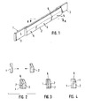
- the bar 1 consists of two strips, of which the strip 1 at the rear in the drawing is longer than the strip 2 at the front.
- the strip 1 has projecting ends 3 which serve to fasten the strip to the respective machine and which are particularly exposed to the attack of driver elements and thus to increased stress.
- the bar 1 is made of hardened steel.
- the cross section of the bar 1 is rectangular.
- shorter strip 2 which consists of unhardened or at least less hard steel and, as in the embodiment shown in FIG. 1, is connected to the strip 1 by welding points 5.
- a soldered or adhesive connection can also be considered without the invention undergoing a fundamental change.
- the groove 6 engages from the top in the track bar.
- this groove 6 extends slightly obliquely to the longitudinal division plane 7 of the two strips 1 and 2. In each of these strips 1 and 2, a part of the groove 6 is incorporated.
- Fig. 2 shows in its upper part that the processing of the strips from their surface is easily possible.
- the groove 6 runs parallel to the longitudinal division plane 7, namely half of it is worked into each of the two strips 1 and 2. 4 down against shows a groove 6, which is incorporated into the shorter strips 2 alone and is limited on the one hand by the surface 4 of the strip 1.
Landscapes
- Engineering & Computer Science (AREA)
- Textile Engineering (AREA)
- Mechanical Engineering (AREA)
- Wire Processing (AREA)
- Knitting Machines (AREA)
Applications Claiming Priority (2)
| Application Number | Priority Date | Filing Date | Title |
|---|---|---|---|
| DE19792944680 DE2944680A1 (de) | 1979-11-06 | 1979-11-06 | Streckenstab fuer textilvorbereitungsmaschinen |
| DE2944680 | 1979-11-06 |
Publications (2)
| Publication Number | Publication Date |
|---|---|
| EP0029113A1 true EP0029113A1 (fr) | 1981-05-27 |
| EP0029113B1 EP0029113B1 (fr) | 1983-05-25 |
Family
ID=6085213
Family Applications (1)
| Application Number | Title | Priority Date | Filing Date |
|---|---|---|---|
| EP19800106129 Expired EP0029113B1 (fr) | 1979-11-06 | 1980-10-09 | Barrette d'aiguilles pour des dispositifs d'étirage de machines textiles de préparation |
Country Status (3)
| Country | Link |
|---|---|
| EP (1) | EP0029113B1 (fr) |
| DD (1) | DD154110A5 (fr) |
| DE (1) | DE2944680A1 (fr) |
Cited By (1)
| Publication number | Priority date | Publication date | Assignee | Title |
|---|---|---|---|---|
| FR2610334A1 (fr) * | 1987-01-30 | 1988-08-05 | Schlumberger Cie N | Dispositif d'etirage pour rubans de fibres textiles |
Citations (3)
| Publication number | Priority date | Publication date | Assignee | Title |
|---|---|---|---|---|
| GB967802A (en) * | 1962-03-09 | 1964-08-26 | Akroyd And Son Ltd S | Improvements in or relating to faller bars for textile combing machines |
| GB1170725A (en) * | 1967-09-09 | 1969-11-12 | Staedtler & Uhl | Improvements in and relating to Needle Strips for Combing and like Machines |
| FR2030379A1 (fr) * | 1969-02-08 | 1970-11-13 | Staedtler & Uhl |
-
1979
- 1979-11-06 DE DE19792944680 patent/DE2944680A1/de not_active Withdrawn
-
1980
- 1980-10-09 EP EP19800106129 patent/EP0029113B1/fr not_active Expired
- 1980-11-05 DD DD22498380A patent/DD154110A5/de unknown
Patent Citations (3)
| Publication number | Priority date | Publication date | Assignee | Title |
|---|---|---|---|---|
| GB967802A (en) * | 1962-03-09 | 1964-08-26 | Akroyd And Son Ltd S | Improvements in or relating to faller bars for textile combing machines |
| GB1170725A (en) * | 1967-09-09 | 1969-11-12 | Staedtler & Uhl | Improvements in and relating to Needle Strips for Combing and like Machines |
| FR2030379A1 (fr) * | 1969-02-08 | 1970-11-13 | Staedtler & Uhl |
Cited By (2)
| Publication number | Priority date | Publication date | Assignee | Title |
|---|---|---|---|---|
| FR2610334A1 (fr) * | 1987-01-30 | 1988-08-05 | Schlumberger Cie N | Dispositif d'etirage pour rubans de fibres textiles |
| EP0277871A1 (fr) * | 1987-01-30 | 1988-08-10 | N. SCHLUMBERGER & CIE | Dispositif d'étirage pour rubans de fibres textiles |
Also Published As
| Publication number | Publication date |
|---|---|
| DD154110A5 (de) | 1982-02-24 |
| EP0029113B1 (fr) | 1983-05-25 |
| DE2944680A1 (de) | 1981-05-07 |
Similar Documents
| Publication | Publication Date | Title |
|---|---|---|
| DE585103C (de) | Maschinenstaender aus duennen Platten | |
| EP0029113B1 (fr) | Barrette d'aiguilles pour des dispositifs d'étirage de machines textiles de préparation | |
| DE3107986A1 (de) | Fenster | |
| DE737550C (de) | Blechbiegepresse | |
| DE544027C (de) | Zahnrad | |
| DE921919C (de) | Einzelteilschraubzwinge | |
| DE3142672A1 (de) | Tischzarge | |
| EP0313056B1 (fr) | Elément de revêtement profilé en bois naturel pour chambranle de porte | |
| DE19854214C1 (de) | Elementsystem | |
| DE19700015C1 (de) | Verfahren zur Herstellung von Verleimprofilen an Hölzern | |
| DE2754519A1 (de) | Befestigungsmittel, insbesondere krallenplatte, zur verbindung von holzbauteilen | |
| DD255040A3 (de) | Verfahren zur herstellung von zahnstangen mit gekruemmter zahnkontur | |
| DE3115285A1 (de) | Verfahren zur herstellung einer kontaktflaeche und einrichtung zu seiner durchfuehrung | |
| DE1190632B (de) | Streifenmesser | |
| DE2544097A1 (de) | Schraubstockbacken fuer werkzeugmaschinen | |
| AT2143U1 (de) | Verschleissfester werkzeugeinsatz | |
| DE378536C (de) | Kopfstuetze von U-Form fuer die Befestigungsmittel der Kleinbahnen | |
| DE3347223C2 (de) | Distanzleisten aus Metall für die Pressenplatte einer Plattenpresse zur Herstellung von Spanplatten, Faserplatten und ähnlichem Preßgut | |
| DE7519511U (de) | Elektrode zum Schweißen von Gitterrosten o.dgl | |
| DE212191C (fr) | ||
| DE2728307A1 (de) | Wendemesserwerkzeug fuer die holz- und kunststoffbearbeitung zum anbringen von flaechen, nuten, profilen usw. | |
| DE1565810A1 (de) | Anordnung elektrisch verschweisster Teile und Verfahren zur Herstellung derselben | |
| DE1902901C (de) | Segmentkreissägeblatt | |
| AT37850B (de) | Verfahren zur Herstellung von Metallkeilen. | |
| AT128708B (de) | Zahnrad. |
Legal Events
| Date | Code | Title | Description |
|---|---|---|---|
| PUAI | Public reference made under article 153(3) epc to a published international application that has entered the european phase |
Free format text: ORIGINAL CODE: 0009012 |
|
| AK | Designated contracting states |
Designated state(s): CH FR GB IT |
|
| 17P | Request for examination filed |
Effective date: 19810414 |
|
| ITCL | It: translation for ep claims filed |
Representative=s name: ING. C. GREGORJ S.P.A. |
|
| ITF | It: translation for a ep patent filed | ||
| GRAA | (expected) grant |
Free format text: ORIGINAL CODE: 0009210 |
|
| AK | Designated contracting states |
Designated state(s): CH FR GB IT LI |
|
| PGFP | Annual fee paid to national office [announced via postgrant information from national office to epo] |
Ref country code: FR Payment date: 19830729 Year of fee payment: 4 |
|
| ET | Fr: translation filed | ||
| PGFP | Annual fee paid to national office [announced via postgrant information from national office to epo] |
Ref country code: CH Payment date: 19830927 Year of fee payment: 4 |
|
| PLBE | No opposition filed within time limit |
Free format text: ORIGINAL CODE: 0009261 |
|
| STAA | Information on the status of an ep patent application or granted ep patent |
Free format text: STATUS: NO OPPOSITION FILED WITHIN TIME LIMIT |
|
| 26N | No opposition filed | ||
| PG25 | Lapsed in a contracting state [announced via postgrant information from national office to epo] |
Ref country code: LI Effective date: 19841031 Ref country code: CH Effective date: 19841031 |
|
| PG25 | Lapsed in a contracting state [announced via postgrant information from national office to epo] |
Ref country code: FR Free format text: LAPSE BECAUSE OF NON-PAYMENT OF DUE FEES Effective date: 19850628 |
|
| REG | Reference to a national code |
Ref country code: CH Ref legal event code: PL |
|
| REG | Reference to a national code |
Ref country code: FR Ref legal event code: ST |
|
| GBPC | Gb: european patent ceased through non-payment of renewal fee | ||
| PG25 | Lapsed in a contracting state [announced via postgrant information from national office to epo] |
Ref country code: GB Free format text: LAPSE BECAUSE OF NON-PAYMENT OF DUE FEES Effective date: 19881118 |