EP0029218A1 - Dispositif de serrage de clichés - Google Patents
Dispositif de serrage de clichés Download PDFInfo
- Publication number
- EP0029218A1 EP0029218A1 EP80106994A EP80106994A EP0029218A1 EP 0029218 A1 EP0029218 A1 EP 0029218A1 EP 80106994 A EP80106994 A EP 80106994A EP 80106994 A EP80106994 A EP 80106994A EP 0029218 A1 EP0029218 A1 EP 0029218A1
- Authority
- EP
- European Patent Office
- Prior art keywords
- plate
- clamping
- levers
- cylinder
- type
- Prior art date
- Legal status (The legal status is an assumption and is not a legal conclusion. Google has not performed a legal analysis and makes no representation as to the accuracy of the status listed.)
- Withdrawn
Links
- 238000007639 printing Methods 0.000 title claims abstract description 19
- 230000008878 coupling Effects 0.000 claims abstract description 9
- 238000010168 coupling process Methods 0.000 claims abstract description 9
- 238000005859 coupling reaction Methods 0.000 claims abstract description 9
- 238000004080 punching Methods 0.000 claims abstract description 5
- 238000007645 offset printing Methods 0.000 claims abstract description 4
- 238000003825 pressing Methods 0.000 claims description 5
- 238000000034 method Methods 0.000 claims description 3
- 230000006835 compression Effects 0.000 abstract description 2
- 238000007906 compression Methods 0.000 abstract description 2
- 238000004049 embossing Methods 0.000 abstract 2
- 239000003086 colorant Substances 0.000 description 2
- 238000013461 design Methods 0.000 description 2
- 206010041953 Staring Diseases 0.000 description 1
- 210000000481 breast Anatomy 0.000 description 1
- 238000010276 construction Methods 0.000 description 1
- 238000012937 correction Methods 0.000 description 1
- 238000011161 development Methods 0.000 description 1
- 230000018109 developmental process Effects 0.000 description 1
- 238000002474 experimental method Methods 0.000 description 1
- 238000005461 lubrication Methods 0.000 description 1
- 239000000463 material Substances 0.000 description 1
- 238000007781 pre-processing Methods 0.000 description 1
- 238000012360 testing method Methods 0.000 description 1
Images


Classifications
-
- B—PERFORMING OPERATIONS; TRANSPORTING
- B41—PRINTING; LINING MACHINES; TYPEWRITERS; STAMPS
- B41F—PRINTING MACHINES OR PRESSES
- B41F27/00—Devices for attaching printing elements or formes to supports
- B41F27/12—Devices for attaching printing elements or formes to supports for attaching flexible printing formes
- B41F27/1262—Devices for attaching printing elements or formes to supports for attaching flexible printing formes without tensioning means
Definitions
- the invention relates to a device for register-correct clamping of printing form plates, in particular offset printing plates on plate cylinders of printing machines.
- the register adjustment devices of the printing presses can usually only adjust the register in the two main directions mentioned. If a register error arises, for example, that the plates are applied to the cylinder in the form of a helical line, possibly with an opposite gradient between the individual colors, then correction using the provided register devices is no longer possible at all. In order to produce perfect prints, the plates then have to be stretched again with a lot of time.
- the ideal solution would be a clamping device that brings the plate onto the cylinder quickly and in accordance with the register, regardless of the skill of the operator.
- the plates are held by axially arranged flat pieces which are inserted into the cylinders and which clamp the front edge of the plate through the friction between the flat underside of a clamping bar and a flat surface on the cylinder.
- the clamping pressure is usually generated with a plurality of distributed in the axial direction o screws.
- the clamping bar is often designed to be divided into one or more parts, and there are devices available for axially displacing the clamping bar segments within certain limits in order to compensate for clamping errors.
- Torquelimiting 0 Tools for tightening the clamping bar screws can only partially overcome this disadvantage, because the set torque is effective as pressing pressure only via the threaded efficiency of the screws. This in turn depends heavily on the condition of the thread, lubrication, etc. In practice, the tolerances of the elements involved are usually greater than the close tolerance of the required pressure. Attempts have been made to make use of interlocking, undulating or triangular-toothed longitudinal grooves in the press beam and counter surface. to increase the friction in the cylinder at a given pressure. However, it can be seen immediately that such a device must inevitably lead to an elongation of the plate in the clamping area, because the formerly flat plate surface adapts to the grooving by permanent deformation. Registering or even pre-registering via pins in the cylinder cannot be achieved with the desired accuracy.
- the present invention is based on the object of avoiding the disadvantages indicated and of specifying a tensioning device for the front edge of the plate which is suitable, with the greatest possible protection of the plate, of applying it to the cylinder in register.
- the invention achieves this by the means mentioned in claim 1.
- Advantageous further developments are specified in subclaims 2 to 6. The invention is described below with reference to Figures 1 to 7.
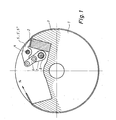
- Fig. 1 shows schematically the arrangement of the clamping device according to the invention in the plate cylinder 1 of a printing press.
- a clamping bar 2 is embedded in a recess in the plate cylinder 1, the flat clamping surface of which for the offset plate 3 merges smoothly into the lateral surface of the plate cylinder.
- a toggle lever mechanism which consists of the articulated couplers 6 and 7, so that they clamp the offset plate 3 plane-parallel between their essentially flat clamping surfaces and the clamping bar 2.
- the actuation takes place by turning a Shaft 8 onto which the couplers 7 are firmly wedged
- the shaft 8 is also rotatably mounted in the end faces of the plate cylinder 1 and has an actuating device (not shown here) outside the cylinder
- an actuating device for example, a lever or a handwheel and a stop that limits the rotation of the shaft somewhat beyond the extended position of the coupling 6 and 7.
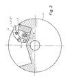
- Fig. 2 shows the mechanism in the open position.
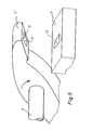
- the coupling 6, as shown schematically in FIG. 3, is designed as a compression spring 9. Since the spring 9 is somewhat longer in the relaxed state than the rigid coupling 6, these clamping levers 5 and 5 'come somewhat closer to contact with their pressure surfaces when the mechanism is actuated and press the offset plate 3 resiliently against the clamping bar 2 with a certain force the offset plate 3 can no longer slip during the further clamping process.
- the resilient clamping levers 5 ' for example in two, which are expediently as far apart as possible, recesses 10 can be incorporated into the clamping surfaces, into which register pins 11 arranged fixedly or removably in the clamping bar engage, as shown schematically in FIG. As a result, the offset plate 3 can be hung on the cylinder 1 with register accuracy even before the clamping, with a corresponding perforation.
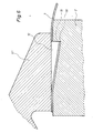
- the third type of tensioning lever 5 is shown in perspective in FIG. 5 and in section in FIG. 6. Stamping dies 12 are incorporated into the tensioning surfaces of these levers, which fit into dies 13 which are incorporated into the clamping bar 2.
- the clamping levers 5 ′′ equipped with punching tools are, as shown in FIG. 4, coupled to the actuating mechanism via rigid couplings is firmly pressed against the clamping bar 2 so that it can no longer slip or warp.
- the pressure of the tensioning levers 5 " given by the geometry of the toggle lever mechanism, is relatively low, so that here too there is no need to fear deformation of the plate.
- the clamping levers in their entirety would not be able to absorb the tangential pull when clamping the plate around cylinder 1.
- This train is applied by a mechanism, not shown here, at 14 at the rear end of the offset plate.
- the pulling force can be over 1000 kg for larger machines. Although this force is reduced by the friction in the wrapping, it is still some 100 kg on the clamping bar.
- Fig. 6 shows the mode of operation of the punch 12 "incorporated in the clamping lever 5" and its dies 13 in the clamping bar 2.
- the breast surface 15 of the punch 12 cuts through the offset plate and thus forms a.
- Support edge 16, which is in the corresponding surface of the die 13 supports and can absorb significant forces in the tangential direction.
- the back 17 of the punch in conjunction with the trough of the die 13 ensures that the non-cut part of the offset plate 3 lies in the trough without creases and that the supporting edge 16 cannot deflect against the pulling direction by deformation.
- the curvature of the punch 12 and the die 13 is shown somewhat exaggerated in the drawing to clarify the mode of operation.
- the sheet height of the punch only has to be on the order of a few offset plate thicknesses. If the support edge 6 then has a certain length in the cylinder axis direction, the plastic deformation of the part of the offset plate 3 pressed into the die also remains small.
Landscapes
- Engineering & Computer Science (AREA)
- Mechanical Engineering (AREA)
- Supply, Installation And Extraction Of Printed Sheets Or Plates (AREA)
Applications Claiming Priority (2)
| Application Number | Priority Date | Filing Date | Title |
|---|---|---|---|
| DE2946597A DE2946597C2 (de) | 1979-11-19 | 1979-11-19 | Einspannvorrichtung für biegsame Druckplatten |
| DE2946597 | 1979-11-19 |
Publications (1)
| Publication Number | Publication Date |
|---|---|
| EP0029218A1 true EP0029218A1 (fr) | 1981-05-27 |
Family
ID=6086355
Family Applications (1)
| Application Number | Title | Priority Date | Filing Date |
|---|---|---|---|
| EP80106994A Withdrawn EP0029218A1 (fr) | 1979-11-19 | 1980-11-13 | Dispositif de serrage de clichés |
Country Status (4)
| Country | Link |
|---|---|
| US (1) | US4359941A (fr) |
| EP (1) | EP0029218A1 (fr) |
| JP (1) | JPS5686755A (fr) |
| DE (1) | DE2946597C2 (fr) |
Families Citing this family (6)
| Publication number | Priority date | Publication date | Assignee | Title |
|---|---|---|---|---|
| JPS5853631U (ja) * | 1981-09-30 | 1983-04-12 | リョービ株式会社 | オフセツト印刷機の版掛装置 |
| JPS5932428U (ja) * | 1982-08-26 | 1984-02-29 | 三菱重工業株式会社 | 版咬え装置 |
| JPS61175446U (fr) * | 1985-04-22 | 1986-11-01 | ||
| DE3626936C1 (de) * | 1986-08-08 | 1988-02-11 | Koenig & Bauer Ag | Plattenklemmeinrichtung |
| US5013319A (en) * | 1989-06-05 | 1991-05-07 | Mount Sinai School Of Medicine Of The City University Of New York | Apparatus and method for cornea marking |
| US5322014A (en) * | 1992-08-25 | 1994-06-21 | Keller James J | Printing plate register system, device, and method |
Citations (5)
| Publication number | Priority date | Publication date | Assignee | Title |
|---|---|---|---|---|
| US2579517A (en) * | 1946-11-01 | 1951-12-25 | Chandler & Price Co | Method of and means for attaching printing members to cylinders of printing presses |
| GB1161393A (en) * | 1966-05-02 | 1969-08-13 | Gestetner Ltd | Improvements in or relating to Clamps in Printing Machinery |
| DE1561082A1 (de) * | 1967-06-20 | 1970-04-16 | Albert Schnellpressen | Vorrichtung zum Einspannen des Druckzylinderaufzuges an Druckmaschinen |
| FR2257427A1 (en) * | 1974-01-14 | 1975-08-08 | Houdaille Industries Inc | Printing plate for clamp unit support - comprises flexible sheet with aligned straight slits lying along a sheet edge |
| DE2626503A1 (de) * | 1976-06-12 | 1977-12-22 | Peter Dipl Ing Dr Ing Decker | Vorrichtung zum befestigen biegsamer druckplatten auf dem formzylinder von druckmaschinen |
Family Cites Families (12)
| Publication number | Priority date | Publication date | Assignee | Title |
|---|---|---|---|---|
| US2553856A (en) * | 1946-03-01 | 1951-05-22 | Addressograph Multigraph | Clamp for master sheets of printing machines |
| US2822754A (en) * | 1950-05-29 | 1958-02-11 | William F Huck | Plate lock-up mechanisms for printing machines |
| FR1278391A (fr) | 1961-01-19 | 1961-12-08 | Machine d'imprimerie en offset comprenant un dispositif de tension pour les feuilles à imprimer | |
| SU371093A1 (ru) * | 1970-04-17 | 1973-02-22 | , вители | Устройство для закрепления формной пластины на цилиндре |
| JPS5528348B2 (fr) * | 1972-07-04 | 1980-07-26 | ||
| US3976005A (en) * | 1974-01-14 | 1976-08-24 | Houdaille Industries, Inc. | Printing plate for use with lockup means |
| JPS5127842U (fr) * | 1974-08-21 | 1976-02-28 | ||
| US4100854A (en) * | 1974-08-28 | 1978-07-18 | Japan Society For Promotion Of Machine Industry | Device for mounting resin plate onto plate cylinder |
| DE2441367B2 (de) * | 1974-08-29 | 1977-12-29 | Japan Society for the Promotion of Machine Industry; Tokyo Kikai Seisakusho, Ltd.; Tokio | Spannvorrichtung eines formzylinders einer druckmaschine |
| DE2501716C2 (de) * | 1975-01-17 | 1982-09-02 | M.A.N. Maschinenfabrik Augsburg-Nürnberg AG, 8900 Augsburg | Vorrichtung zum Befestigen einer biegsamen Druckplatte auf dem Plattenzylinder einer Rotationsdruckmaschine |
| JPS58110B2 (ja) * | 1975-08-29 | 1983-01-05 | 松下電器産業株式会社 | シンゴウサイセイソウチ |
| DE2744371C3 (de) | 1977-10-01 | 1980-04-10 | Albert-Frankenthal Ag, 6710 Frankenthal | Vorrichtung zum Befestigen und Spannen von biegsamen Druckplatten |
-
1979
- 1979-11-19 DE DE2946597A patent/DE2946597C2/de not_active Expired
-
1980
- 1980-11-13 EP EP80106994A patent/EP0029218A1/fr not_active Withdrawn
- 1980-11-19 JP JP16206180A patent/JPS5686755A/ja active Pending
- 1980-11-19 US US06/208,435 patent/US4359941A/en not_active Expired - Lifetime
Patent Citations (5)
| Publication number | Priority date | Publication date | Assignee | Title |
|---|---|---|---|---|
| US2579517A (en) * | 1946-11-01 | 1951-12-25 | Chandler & Price Co | Method of and means for attaching printing members to cylinders of printing presses |
| GB1161393A (en) * | 1966-05-02 | 1969-08-13 | Gestetner Ltd | Improvements in or relating to Clamps in Printing Machinery |
| DE1561082A1 (de) * | 1967-06-20 | 1970-04-16 | Albert Schnellpressen | Vorrichtung zum Einspannen des Druckzylinderaufzuges an Druckmaschinen |
| FR2257427A1 (en) * | 1974-01-14 | 1975-08-08 | Houdaille Industries Inc | Printing plate for clamp unit support - comprises flexible sheet with aligned straight slits lying along a sheet edge |
| DE2626503A1 (de) * | 1976-06-12 | 1977-12-22 | Peter Dipl Ing Dr Ing Decker | Vorrichtung zum befestigen biegsamer druckplatten auf dem formzylinder von druckmaschinen |
Also Published As
| Publication number | Publication date |
|---|---|
| US4359941A (en) | 1982-11-23 |
| DE2946597A1 (de) | 1981-05-21 |
| DE2946597C2 (de) | 1983-03-17 |
| JPS5686755A (en) | 1981-07-14 |
Similar Documents
| Publication | Publication Date | Title |
|---|---|---|
| EP0132532B1 (fr) | Cylindre pour une machine rotative d'impression | |
| DE10152020A1 (de) | Vorrichtungen zum Einstellen des Anpressdrucks einer verstellbar gelagerten Walze | |
| DE3516682A1 (de) | Vorrichtung zum parallelen spannen von druckplatten auf dem plattenzylinder von druckmaschinen | |
| DE69500974T2 (de) | Vorrichtung zur Befestigung von biegsamen Druckplatten auf einem Druckzylinder | |
| DE69507687T2 (de) | Rakelklemmanordnung für eine druckmaschine | |
| EP0196688A2 (fr) | Cylindre à couteaux pour traiter des matériaux en bandes | |
| DE2456303C2 (de) | Kantenbiegemaschine für metallene Druckplatten | |
| DE4444062A1 (de) | Verstellbare Ausrichtvorrichtung für Druckplatten | |
| DE2946597C2 (de) | Einspannvorrichtung für biegsame Druckplatten | |
| DE388029C (de) | Aufspannvorrichtung fuer biegsame Druckplatten an Gummidruckrotationsmaschinen | |
| DE4321751C1 (de) | Vorrichtung zum paßgenauen Spannen von Druckplatten auf dem Plattenzylinder von Druckmaschinen | |
| DE3884939T2 (de) | Spannungsloser Plattenverschluss. | |
| DE69500309T2 (de) | Vorrichtung zum Befestigen einer Greiferstange zu einem Kettensystem in einer Maschine zur Behandlung von plattenförmigen Elementen | |
| EP0425935B1 (fr) | Dispositif de mise en tension parallèle des plaques d'impression | |
| CH628285A5 (en) | Sheet-holding device of a sheet-fed rotary printing machine which is capable of slightly deforming the printing sheet | |
| DE10113314A1 (de) | Fixiereinrichtung | |
| EP0429808B1 (fr) | Dispositif pour tendre avec un repérage exact une plaque d'impression sur un cylindre d'impression | |
| DE2626503A1 (de) | Vorrichtung zum befestigen biegsamer druckplatten auf dem formzylinder von druckmaschinen | |
| DE2328954A1 (de) | Auflager fuer einen druckplattenzylinder | |
| EP0534214B1 (fr) | Procédé et dispositif pour la correction de divergences trapézoidales des repères | |
| DE7932632U1 (de) | Aufspannvorrichtung fuer druckformplatten | |
| DE4310299C1 (de) | Seitenmarkeneinrichtung | |
| DE4226192C2 (de) | Verfahren und Vorrichtung zur Korrektur trapezartiger Passerabweichungen | |
| DE3220530C2 (de) | Vorrichtung zum Aufspannen von Tiefdruckplatten | |
| DE3521590C1 (de) | Bogenglaetteinrichtung fuer die Greiferkante eines Bogens an der Bogenanlage einer Bogenrotationsdruckmaschine |
Legal Events
| Date | Code | Title | Description |
|---|---|---|---|
| PUAI | Public reference made under article 153(3) epc to a published international application that has entered the european phase |
Free format text: ORIGINAL CODE: 0009012 |
|
| AK | Designated contracting states |
Designated state(s): CH FR GB IT NL SE |
|
| 17P | Request for examination filed |
Effective date: 19810424 |
|
| STAA | Information on the status of an ep patent application or granted ep patent |
Free format text: STATUS: THE APPLICATION IS DEEMED TO BE WITHDRAWN |
|
| 18D | Application deemed to be withdrawn |
Effective date: 19821210 |
|
| RIN1 | Information on inventor provided before grant (corrected) |
Inventor name: FELS, WERNER |