EP0029224A2 - Pompe à chaleur à sorption avec accumulateur d'eau chaude sanitaire - Google Patents
Pompe à chaleur à sorption avec accumulateur d'eau chaude sanitaire Download PDFInfo
- Publication number
- EP0029224A2 EP0029224A2 EP80107013A EP80107013A EP0029224A2 EP 0029224 A2 EP0029224 A2 EP 0029224A2 EP 80107013 A EP80107013 A EP 80107013A EP 80107013 A EP80107013 A EP 80107013A EP 0029224 A2 EP0029224 A2 EP 0029224A2
- Authority
- EP
- European Patent Office
- Prior art keywords
- heat pump
- arrangement
- absorber
- heating
- sorption
- Prior art date
- Legal status (The legal status is an assumption and is not a legal conclusion. Google has not performed a legal analysis and makes no representation as to the accuracy of the status listed.)
- Granted
Links
Images

Classifications
-
- F—MECHANICAL ENGINEERING; LIGHTING; HEATING; WEAPONS; BLASTING
- F25—REFRIGERATION OR COOLING; COMBINED HEATING AND REFRIGERATION SYSTEMS; HEAT PUMP SYSTEMS; MANUFACTURE OR STORAGE OF ICE; LIQUEFACTION SOLIDIFICATION OF GASES
- F25B—REFRIGERATION MACHINES, PLANTS OR SYSTEMS; COMBINED HEATING AND REFRIGERATION SYSTEMS; HEAT PUMP SYSTEMS
- F25B30/00—Heat pumps
- F25B30/04—Heat pumps of the sorption type
-
- F—MECHANICAL ENGINEERING; LIGHTING; HEATING; WEAPONS; BLASTING
- F24—HEATING; RANGES; VENTILATING
- F24D—DOMESTIC- OR SPACE-HEATING SYSTEMS, e.g. CENTRAL HEATING SYSTEMS; DOMESTIC HOT-WATER SUPPLY SYSTEMS; ELEMENTS OR COMPONENTS THEREFOR
- F24D3/00—Hot-water central heating systems
- F24D3/18—Hot-water central heating systems using heat pumps
-
- F—MECHANICAL ENGINEERING; LIGHTING; HEATING; WEAPONS; BLASTING
- F24—HEATING; RANGES; VENTILATING
- F24H—FLUID HEATERS, e.g. WATER OR AIR HEATERS, HAVING HEAT-GENERATING MEANS, e.g. HEAT PUMPS, IN GENERAL
- F24H4/00—Fluid heaters characterised by the use of heat pumps
- F24H4/02—Water heaters
- F24H4/04—Storage heaters
-
- F—MECHANICAL ENGINEERING; LIGHTING; HEATING; WEAPONS; BLASTING
- F25—REFRIGERATION OR COOLING; COMBINED HEATING AND REFRIGERATION SYSTEMS; HEAT PUMP SYSTEMS; MANUFACTURE OR STORAGE OF ICE; LIQUEFACTION SOLIDIFICATION OF GASES
- F25B—REFRIGERATION MACHINES, PLANTS OR SYSTEMS; COMBINED HEATING AND REFRIGERATION SYSTEMS; HEAT PUMP SYSTEMS
- F25B15/00—Sorption machines, plants or systems, operating continuously, e.g. absorption type
- F25B15/02—Sorption machines, plants or systems, operating continuously, e.g. absorption type without inert gas
- F25B15/04—Sorption machines, plants or systems, operating continuously, e.g. absorption type without inert gas the refrigerant being ammonia evaporated from aqueous solution
-
- Y—GENERAL TAGGING OF NEW TECHNOLOGICAL DEVELOPMENTS; GENERAL TAGGING OF CROSS-SECTIONAL TECHNOLOGIES SPANNING OVER SEVERAL SECTIONS OF THE IPC; TECHNICAL SUBJECTS COVERED BY FORMER USPC CROSS-REFERENCE ART COLLECTIONS [XRACs] AND DIGESTS
- Y02—TECHNOLOGIES OR APPLICATIONS FOR MITIGATION OR ADAPTATION AGAINST CLIMATE CHANGE
- Y02A—TECHNOLOGIES FOR ADAPTATION TO CLIMATE CHANGE
- Y02A30/00—Adapting or protecting infrastructure or their operation
- Y02A30/27—Relating to heating, ventilation or air conditioning [HVAC] technologies
-
- Y—GENERAL TAGGING OF NEW TECHNOLOGICAL DEVELOPMENTS; GENERAL TAGGING OF CROSS-SECTIONAL TECHNOLOGIES SPANNING OVER SEVERAL SECTIONS OF THE IPC; TECHNICAL SUBJECTS COVERED BY FORMER USPC CROSS-REFERENCE ART COLLECTIONS [XRACs] AND DIGESTS
- Y02—TECHNOLOGIES OR APPLICATIONS FOR MITIGATION OR ADAPTATION AGAINST CLIMATE CHANGE
- Y02B—CLIMATE CHANGE MITIGATION TECHNOLOGIES RELATED TO BUILDINGS, e.g. HOUSING, HOUSE APPLIANCES OR RELATED END-USER APPLICATIONS
- Y02B30/00—Energy efficient heating, ventilation or air conditioning [HVAC]
- Y02B30/12—Hot water central heating systems using heat pumps
-
- Y—GENERAL TAGGING OF NEW TECHNOLOGICAL DEVELOPMENTS; GENERAL TAGGING OF CROSS-SECTIONAL TECHNOLOGIES SPANNING OVER SEVERAL SECTIONS OF THE IPC; TECHNICAL SUBJECTS COVERED BY FORMER USPC CROSS-REFERENCE ART COLLECTIONS [XRACs] AND DIGESTS
- Y02—TECHNOLOGIES OR APPLICATIONS FOR MITIGATION OR ADAPTATION AGAINST CLIMATE CHANGE
- Y02B—CLIMATE CHANGE MITIGATION TECHNOLOGIES RELATED TO BUILDINGS, e.g. HOUSING, HOUSE APPLIANCES OR RELATED END-USER APPLICATIONS
- Y02B30/00—Energy efficient heating, ventilation or air conditioning [HVAC]
- Y02B30/62—Absorption based systems
Definitions
- the invention relates to a sorption heat pump with a connected hot water tank, with a sorption unit consisting of an expeller, an evaporator with an upstream, controllable expansion valve and an absorber and a condenser.
- the heat pump systems with connected hot water preparation are known as the electric motor-operated and the internal combustion engine-operated compression heat pump, in which a mechanical compressor is driven by an electric motor or internal combustion engine.
- a mechanical compressor is driven by an electric motor or internal combustion engine.
- the object of the invention is to provide a sorption heat pump with a connected domestic hot water tank of the type mentioned, in which, with a simple structure, the primary energy can be supplied to the domestic hot water heating system in a low-loss manner via a sorption process via a sorption process, and thus a good efficiency of the system is achieved.
- the object on which the invention is based is achieved in that all of the working medium, such as ammonia, components are combined in a compact first arrangement, while the non-working medium components, such as hot water tanks, valves, pumps and electronic monitoring and control, are combined in a second compact Arrangement are summarized.
- working medium such as ammonia
- non-working medium components such as hot water tanks, valves, pumps and electronic monitoring and control
- the arrangement is in particular such that the water-cooled absorber together with the condenser serves as a heat exchanger for heating the heating water.
- the absorber cooling can expediently be designed as a helical coil system, around which heating water flows around the outside.
- an advantageous development of the invention provides that the absorber solution recirculation unit located at a higher temperature level is arranged in the inner hollow cylinder of the absorber cooling.
- both the condenser and the evaporator are designed as helical coils, the inner diameter of the helical arrangement being selected such that the condenser and the evaporator are the water-cooled, which are at a higher temperature level Wrap the absorber.
- a storage tank can be provided for integral hot water heating, a pipe spiral being formed for supplying the heat, through which the heating water flows if necessary in a priority circuit.
- first arrangement and the second arrangement are combined by sheet metal cladding.
- the individual components are thus connected in terms of process technology in such a way that the lowest possible heat losses occur. In this way, a good efficiency of the system is achieved.
- domestic water heating and the storage of domestic hot water are an integral part of the overall unit.
- a particular advantage is the simple assembly and maintenance of the system, since the first and the second arrangement of the individual components each as a subsystem in the form of an assembly and maintenance unit are constructed, which is easily accessible for an operator.
- the sorption process known from refrigeration technology for example using the ammonia / water pair, is used in such a way that it is possible to generate heating process temperatures that are required for the predominant period (up to approx. 90%) of a heating period Components and heat exchangers known from refrigeration technology are used.
- the heat pump system comprises an expeller or cooker, in which e.g. Ammonia vapor is expelled from water with a high ammonia content by supplying heat. Heating oil, natural gas, solid fuels and electrical energy can be used as heating medium. The expelled steam condenses in the condenser, where it releases its heat of condensation into the heating water. The liquid ammonia is expanded to a low pressure by an expansion valve and fed to the evaporator, where it evaporates from the environment while absorbing heat. The evaporated ammonia is fed to the absorber, which in turn receives the ammonia-depleted solution from the expeller.
- Ammonia vapor is expelled from water with a high ammonia content by supplying heat. Heating oil, natural gas, solid fuels and electrical energy can be used as heating medium.
- the expelled steam condenses in the condenser, where it releases its heat of condensation into the heating water.
- the liquid ammonia is expanded to a low pressure by an expansion valve and fed to the evaporator,
- the hot ammoniacal water from the expeller is fed to the absorber via a second expansion valve, where it releases the ammonia vapor coming from the evaporator while releasing heat.
- the ammonia solution enriched in the absorber unit is pumped back into the expeller via a circulation pump, where the expulsion process begins again.
- the connecting lines between the two assembly units only carry heating water, brine or hydraulic oil.
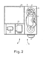
- the first arrangement A and the second arrangement B of the individual components are shown in a compact manner, such that the components carrying the working medium in a first arrangement A according to the drawing on the right and the individual components not carrying the working medium in a second Arrangement B is located close to the left of the first arrangement A as shown in the drawing and is connected to one another in a suitable manner.
- the first arrangement A essentially comprises the sorption unit consisting of a dephlegmator 1, an absorber cooling 2, an evaporator 3, an ammonia tank 4, a membrane pump 5 and a condenser 6.
- the expeller 7 is heated by a burner 9, while the rectifier at 8 is provided.
- the second arrangement B essentially comprises a domestic hot water tank 2o, valves 21, and pumps 22 and 23. Furthermore, an electronic monitoring and control unit 28 is integrated in this arrangement. Furthermore, the second arrangement B has supply and discharge lines for the process water 31, the brine 32 and the heater 30. Both arrangements A and B are connected to each other with only a minimum of connecting lines, namely for the heating water, the brine or the hydraulic oil.
- the spatial arrangement of the units is designed so that the water-cooled absorber, which, together with the condenser 6, transfers the heat into the heating circuit, is designed as a coil system.
- the unit for the solution feedback is located in the interior of the water-cooled absorber. With this arrangement, the heat radiation caused by the solution recirculation at high temperature is absorbed directly by the heating water via the external cooling jacket.
- the capacitor 6 is designed as a coaxial coil system and placed around the absorber, the radiant heat emitted by the absorber at a higher temperature from the cooling jacket of the Capacitor 6 is added.
- the ammonia is evaporated in a coiled tube system, which is surrounded by an envelope jacket that guides the brine and is arranged coaxially to the absorber. In order to prevent excessive heat exchange between evaporator 3 and absorber, appropriate thermal insulation is introduced into the annular gap.
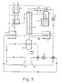
- FIG. 3 the integral circuit diagram of the system is shown schematically.
- the individual components determining the sorption unit are shown here according to the drawing above and the components which characterize the second arrangement B are shown below.
- the individual components have essentially already been described in connection with FIGS. 1 and 2.
- the circuit diagram also shows a solution pump 1 0, reactors 11 and 12 and the absorber 13 and the temperature changer 14.
- the reference numerals 26 and 27 are in the supply manifold or return manifold, while the cold water pipe is provided with the reference numeral 25 with respect to the Sorptionsaggregates.
- the hot water heating and hot water storage are clearly an integral part of the overall unit of an absorber heating with combined hot water treatment.
- valves 21 and pumps 23 which according to the invention are in one Priority circuit for heating the domestic hot water tank are required, are summarized according to Figures 1 and 2 in a separate mounting frame to form a maintenance unit, which is housed together with the Soprtionsaggregat in a housing.
- the invention thus relates to a sorption heat pump with a connected domestic hot water storage tank, the primary energy, with the exception of a small loss due to heat radiation and exhaust gas heat, being transferred via a sorption process to a heating system for domestic water treatment and, by means of the energy contained in the primary energy, an additional considerable proportion of energy from the environment (air, Groundwater, geothermal or waste heat) is pumped into the heating system.
Landscapes
- Engineering & Computer Science (AREA)
- Physics & Mathematics (AREA)
- Thermal Sciences (AREA)
- Mechanical Engineering (AREA)
- General Engineering & Computer Science (AREA)
- Chemical & Material Sciences (AREA)
- Combustion & Propulsion (AREA)
- Sorption Type Refrigeration Machines (AREA)
- Thermally Insulated Containers For Foods (AREA)
- Heat-Pump Type And Storage Water Heaters (AREA)
Priority Applications (1)
| Application Number | Priority Date | Filing Date | Title |
|---|---|---|---|
| AT80107013T ATE5279T1 (de) | 1979-11-15 | 1980-11-13 | Sorptionswaermepumpe mit angeschlossenem brauchwasserspeicher. |
Applications Claiming Priority (2)
| Application Number | Priority Date | Filing Date | Title |
|---|---|---|---|
| DE2946076 | 1979-11-15 | ||
| DE2946076A DE2946076C2 (de) | 1979-11-15 | 1979-11-15 | Sorptionswärmepumpe |
Publications (3)
| Publication Number | Publication Date |
|---|---|
| EP0029224A2 true EP0029224A2 (fr) | 1981-05-27 |
| EP0029224A3 EP0029224A3 (en) | 1981-07-22 |
| EP0029224B1 EP0029224B1 (fr) | 1983-11-09 |
Family
ID=6086022
Family Applications (1)
| Application Number | Title | Priority Date | Filing Date |
|---|---|---|---|
| EP80107013A Expired EP0029224B1 (fr) | 1979-11-15 | 1980-11-13 | Pompe à chaleur à sorption avec accumulateur d'eau chaude sanitaire |
Country Status (3)
| Country | Link |
|---|---|
| EP (1) | EP0029224B1 (fr) |
| AT (1) | ATE5279T1 (fr) |
| DE (1) | DE2946076C2 (fr) |
Cited By (2)
| Publication number | Priority date | Publication date | Assignee | Title |
|---|---|---|---|---|
| ES2122845A1 (es) * | 1995-02-14 | 1998-12-16 | Frinta S A | Maquina productora de frio en ciclo de absorcion. |
| EP1645815A1 (fr) * | 2004-10-08 | 2006-04-12 | Viessmann Werke GmbH & Co. KG | Appareil de sorption |
Families Citing this family (1)
| Publication number | Priority date | Publication date | Assignee | Title |
|---|---|---|---|---|
| DE102007022950A1 (de) * | 2007-05-16 | 2008-11-20 | Weiss, Dieter | Verfahren zum Transport von Wärmeenergie und Vorrichtungen zur Durchführung eines solchen Verfahrens |
Family Cites Families (5)
| Publication number | Priority date | Publication date | Assignee | Title |
|---|---|---|---|---|
| GB731261A (en) * | 1951-03-20 | 1955-06-08 | British Thomson Houston Co Ltd | Improvements in and relating to water heating and room cooling systems |
| DE947246C (de) * | 1952-08-09 | 1956-08-16 | Licentia Gmbh | Kuehlschrank mit Warmwasserbereitung |
| US3907025A (en) * | 1973-04-13 | 1975-09-23 | Columbia Gas Syst | Compact heating and cooling system |
| US3964273A (en) * | 1975-02-13 | 1976-06-22 | Arkla Industries, Inc. | Compact absorption refrigeration apparatus |
| DE2604942A1 (de) * | 1976-02-09 | 1977-08-11 | Karl Dr Ing Schmidt | Waermepumpe |
-
1979
- 1979-11-15 DE DE2946076A patent/DE2946076C2/de not_active Expired
-
1980
- 1980-11-13 AT AT80107013T patent/ATE5279T1/de not_active IP Right Cessation
- 1980-11-13 EP EP80107013A patent/EP0029224B1/fr not_active Expired
Cited By (2)
| Publication number | Priority date | Publication date | Assignee | Title |
|---|---|---|---|---|
| ES2122845A1 (es) * | 1995-02-14 | 1998-12-16 | Frinta S A | Maquina productora de frio en ciclo de absorcion. |
| EP1645815A1 (fr) * | 2004-10-08 | 2006-04-12 | Viessmann Werke GmbH & Co. KG | Appareil de sorption |
Also Published As
| Publication number | Publication date |
|---|---|
| DE2946076C2 (de) | 1985-10-31 |
| EP0029224A3 (en) | 1981-07-22 |
| ATE5279T1 (de) | 1983-11-15 |
| EP0029224B1 (fr) | 1983-11-09 |
| DE2946076A1 (de) | 1981-05-27 |
Similar Documents
| Publication | Publication Date | Title |
|---|---|---|
| DE3739831C2 (de) | Verfahren zur Wärmeabsorption durch eine Absorptionskältemaschine und Vorrichtung für die Verwendung als Absorptionskältemaschine | |
| EP0026257B1 (fr) | Installation comportant une pompe à chaleur à absorption | |
| DE68908590T2 (de) | Wassererhitzer. | |
| EP0216237A2 (fr) | Accumulateur à sorption à marche discontinue avec un absorbeur contenant un solide | |
| DE69129212T2 (de) | Absorptionskühl- und wärmepumpenanlage mit enteisung | |
| WO1990010835A1 (fr) | Absorbeur pour un systeme d'absorption diffusion | |
| DE2747813A1 (de) | Anlage mit einer waermepumpe zur raumheizung und brauchwasseraufbereitung | |
| EP0046196B1 (fr) | Procédé pour le fonctionnement d'une installation de chauffage à absorption monovalente et alternative | |
| DE3686731T2 (de) | Waermepumpenanlage. | |
| DE102018111056A1 (de) | Heizungs- und/oder Warmwasserbereitungssystem | |
| DE2648855A1 (de) | Einrichtung zur senkung der durch rauchgase bedingten waermeverluste bei einem mit oel oder gas betriebenen heizkessel | |
| EP0733190B1 (fr) | Dispositif de refroidissement comportant une unite frigorifique a fonctionnement intermittent | |
| EP0029224B1 (fr) | Pompe à chaleur à sorption avec accumulateur d'eau chaude sanitaire | |
| DE10108768C2 (de) | Absorptionskälteanlage mit Niedertemperaturnutzung | |
| DE69921871T2 (de) | Absorptionskälteanlage mit Kupplung von Kondensat und Lösung | |
| DE102019001642A1 (de) | Heizungs-und/oder Warmwasserbereitungssystem | |
| DE3018709A1 (de) | Parallel-bivalent als absorber-waermepumpe und heizkessel arbeitende zum erwaermen eines waermetraegermediums | |
| DE2457578B2 (fr) | ||
| EP0036981B1 (fr) | Procédé pour le fonctionnement d'une installation de chauffage à absorption | |
| DE3031624C2 (de) | Wärmerohranordnung zum Temperieren eines Fahrgast- oder Nutzraumes eines brennkraftgetriebenen Fahrzeuges | |
| DE3819535C2 (de) | Wärmetauscher | |
| EP2588817A2 (fr) | Système de capteurs solaires et procédé de commande correspondant | |
| DE102010008408B4 (de) | Verfahren zum Betreiben eines Rückkühlkreislaufes mit einem Hybridkühler für eine Anlage mit einer diskontinuierlichen Wärmeabgabe und Vorrichtung hierfür | |
| DE10019302A1 (de) | Wärmepumpe zur Heizungs- und Brauchwassererwärmung | |
| AT409300B (de) | Adsorptionswärmepumpe |
Legal Events
| Date | Code | Title | Description |
|---|---|---|---|
| PUAI | Public reference made under article 153(3) epc to a published international application that has entered the european phase |
Free format text: ORIGINAL CODE: 0009012 |
|
| PUAL | Search report despatched |
Free format text: ORIGINAL CODE: 0009013 |
|
| AK | Designated contracting states |
Designated state(s): AT BE CH FR NL |
|
| AK | Designated contracting states |
Designated state(s): AT BE CH FR NL |
|
| RBV | Designated contracting states (corrected) |
Designated state(s): AT BE CH FR LI NL |
|
| 17P | Request for examination filed |
Effective date: 19820114 |
|
| GRAA | (expected) grant |
Free format text: ORIGINAL CODE: 0009210 |
|
| AK | Designated contracting states |
Designated state(s): AT BE CH FR LI NL |
|
| REF | Corresponds to: |
Ref document number: 5279 Country of ref document: AT Date of ref document: 19831115 Kind code of ref document: T |
|
| PGFP | Annual fee paid to national office [announced via postgrant information from national office to epo] |
Ref country code: CH Payment date: 19831126 Year of fee payment: 4 |
|
| PGFP | Annual fee paid to national office [announced via postgrant information from national office to epo] |
Ref country code: NL Payment date: 19831130 Year of fee payment: 4 Ref country code: FR Payment date: 19831130 Year of fee payment: 4 Ref country code: BE Payment date: 19831130 Year of fee payment: 4 Ref country code: AT Payment date: 19831130 Year of fee payment: 4 |
|
| ET | Fr: translation filed | ||
| PLBE | No opposition filed within time limit |
Free format text: ORIGINAL CODE: 0009261 |
|
| STAA | Information on the status of an ep patent application or granted ep patent |
Free format text: STATUS: NO OPPOSITION FILED WITHIN TIME LIMIT |
|
| 26N | No opposition filed | ||
| PG25 | Lapsed in a contracting state [announced via postgrant information from national office to epo] |
Ref country code: AT Effective date: 19841113 |
|
| PG25 | Lapsed in a contracting state [announced via postgrant information from national office to epo] |
Ref country code: LI Effective date: 19841130 Ref country code: CH Effective date: 19841130 Ref country code: BE Effective date: 19841130 |
|
| BERE | Be: lapsed |
Owner name: MAN MASCHINENFABRIK AUGSBURG-NURNBERG A.G. Effective date: 19841113 |
|
| PG25 | Lapsed in a contracting state [announced via postgrant information from national office to epo] |
Ref country code: NL Effective date: 19850601 |
|
| NLV4 | Nl: lapsed or anulled due to non-payment of the annual fee | ||
| PG25 | Lapsed in a contracting state [announced via postgrant information from national office to epo] |
Ref country code: FR Free format text: LAPSE BECAUSE OF NON-PAYMENT OF DUE FEES Effective date: 19850731 |
|
| REG | Reference to a national code |
Ref country code: CH Ref legal event code: PL |
|
| REG | Reference to a national code |
Ref country code: FR Ref legal event code: ST |